1
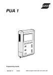
User Manual
DP403SW
DP503SW
ISSUE 2
USER AND MAIINTENANCE MANUAL
Parweld would like to thank you for choosing this machine; if used according to the instructions reported in this user and
maintenance manual, it will accompany you in your work for many years without any problems. This manual is an integral
part of the machine and must accompany it whenever moved or resold. The user is responsible for making sure the machine
is complete and in good working order. The manufacturer has the right to make changes at any time, without notice. No
part of this manual may be translated into another language, adapted or reproduced with any means (including scanned
documents, photocopies, film and microfilm) without the prior written consent of the manufacturer
INDEX
• CAUTION ......................................................................................... NOMINAL DATA ..................................................................................................... 1. GENERAL SPECIFICATIONS AND NOTES FOR CONSULTING
THIS MANUAL ............................................................................................... 2. DESCRIPTION OF THE EQUIPMENT .......................................................... 3. LOADING THE WELDING WIRE................................................................... 4. MIG/MAG WELDING...................................................................................... 4. 1 Manual Short Arc MIG Welding ................................................................... 4. 2 Synergic Short Arc MIG WELDING ............................................................ 4. 3 Pulse synergic MIG WELDING ................................................................... 5. MIG WELDING CONECTOR.......................................................................... 5. 2 CONNECTOR FOR MIG WELDING with a traditional torch....................... 5. 3 CONNECTOR FOR MIG WELDING with a Spool or Push-Pull torch ...... 6. STRIKING AN ARC IN MIG WELDING.......................................................... 7. ADJUSTING THE WELDER........................................................................... 8. HOW TO ACHIEVE THE BEST WELDING RESULTS.................................. 9. MMA WELDING.............................................................................................. 9. 1 MMA WELDING Manual ............................................................................... 10 WELDING TABLE.......................................................................................... 11 CONNECTION FOR MMA WELDING............................................................ 12. IGNITING THE MMA ARC ............................................................................. 13. TIG WELDING................................................................................................ 13. 1 TIG WELDING (Lift-Arc) ............................................................................... 14. CONNECTOR FOR TIG WELDING ............................................................. 15. IGNITION OF THE TIG ARC.......................................................................... 16. POWER CONNECTOR.................................................................................. 17. REMOTE CONNECTION ............................................................................... 17.1 REMOTE CONTROL OF THE WELDING CURRENT ................................... 18. CONNECTING THE OUTPUTS .................................................................... 19. CONNECTING THE GAS CYLINDER AND THE GAS REGULATOR 20. ORDINARY MACHINE MAINTENANCE........................................................ 22. MEMORISING THE WORK POINT................................................................ 23. LOCKING A WORK POINT............................................................................ 24. TROUBLESHOOTING ................................................................................... 25. BLOCK DIAGRAM WIRE FEEDER............................................................... 26. BLOCK DIAGRAM GENERATOR.................................................................. 27. SPARE PARTS DP403SW........................ .................................................... 28. SPARE PARTS DP503SW............. ............................................................... 29. SPARE PARTS WIRE FEEDER .................................................................... page. 2, 3, 4
page 5
page 6
page. 6
page. 9
page. 10
page. 10
page. 11
page. 13
page. 14
page. 15
page. 15
page. 15
page. 15
page. 15
page. 16
page. 16
page. 17
page. 17
page. 17
page. 18
page. 18
page. 19
page. 19
page. 20
page. 20
page. 20
page. 20
page. 20
page. 21
page. 21
page. 21
page. 24
page. 25
page. 25
page. 26
page. 27
page. 28
CONTENTS
2
3
www.parweld.com
4
www.parweld.com
DP353
5
www.parweld.com
DP403SW
DP503SW
1. GENERAL SPECIFICATIONS AND
NOTES FOR CONSULTING THIS MANUAL
The DP403SW, and DP 503SW welders are made using
INVERTER technology. They are extremely
compact and versatile devices that can be
used in all those situations that require
minimum obstruction, combined with the
highest performance.
These welders use both manual and synergic
MMA, TIG and MIG/MAG (short arc, pulse or
double pulse).
The innovative operator interface system, which
uses a large 5,7” TFT colour screen, allows for
simple and intuitive use of the equipment,
without renouncing on the possibility to
personalise all of the welding settings.
All of the main parameters of the machine
are stored on a memory card (SD-Card),
keeping the equipment constantly up-dated
with the latest welding developments. If the
memory card is removed the equipment will
cease to function, providing an optimal antitheft
system and safeguard against
inappropriate use. Thanks to the advanced
control techniques adopted, the product is
extremely reliable and easy to use.
This instruction manual provides detailed
ONLY FOR
DP503
information on the machine settings: reading
the entire manual will allow you to appreciate
the extreme flexibility and practicality of use.
Caution: the device must only be used in the
manner and for the purpose described in this
manual. Never use inappropriately or for any
other purpose.
6
www.parweld.com
1. Graphic display: The 5,7’’ colour screen displays
different screens, according to the welding mode or
settings. In weld mode the display is divided into five
principal:
Part 1: Machine status
Part 2: Meaning of the active buttons (buttons 2, 3, 4,
5,6 di fig.1)
Part 3: Size values set
Part 4: Type of process selected
Part 5: Indicates the values that can be set for the
various welding settings (to change the values select
using switch 10 and confirm the selection by pressing
the same switch; the value will be highlighted in a
contrasting colour. The values can be changed by
turning the switch, to confirm the new value press the
switch again. 10).
Highlighted value: Indicates the parameter that is being
changed using switch 10.
DISPLAYS: - When the screen comes on, the Parweld
logo will appear and the Firmware revisions will load.
CONTROL BUTTONS: (2, 3, 4, 5,6 in fig.1)
Each control button is associated with a specific
function shown on the display.
7. SD slot: this slot, covered with a rubber cap,
contains the SD-Card provided with the machine;
without the card, the machine will be inactive and a
warning message will appear on the screen.
7
www.parweld.com
8. USB port: for technical assistance only. 9. Switch for
adjusting the principal welding settings: This switch is
used to set the principal welding parameters: MMA/TIG
Welding; set the welding current
11. H²O in: to be used only with liquid cooling torches.
12. H²O out: to be used only with liquid cooling
torches.
13. Connector for remote control.
14. “+” dinse front connector: positive pole inlet. MMA
Mode: Electrode holder
15. EUROCONNECTOR (SEPARATED TROLLEY):
quick connector for welding torch. This connector is
used to supply welding gas to the torch, the electrical
contacts of the torch button and the welding current.
16. ON-OFF switch: turns the machine on and off.
DP503SW machine is equipped by hydromagnetic for
this purpose, as showed in pic. 16
17. “-” dinse front connector: negative pole inlet.
MMA Mode: Ground clamp
TIG Mode: TIG torch
MIG Mode with gas: Not used
MIG without gas mode: Not used
18. “+” dinse front connector: positive pole inlet.
MMA Mode: Electrode holder
MIG Mode: Ground clamp
MIG with gas mode: Not used
MIG without gas mode: Not used
19. TIG gas Outlet
20. MIG signal connector: Connection of the signals to
the push-pull torch
21. Filling cap of the cooling liquid (Optional) (Cooling
unit)
22. H²O in: To be used only with liquid cooling torches.
23. AIR GRILL 24. ON-OFF switch and light of the
control unit (Option): This lights up when the cooling
system is fed.
24. ON-OFF switch and light of the control
unit (Option): This lights up when the
cooling system is fed.
which are necessary for CAN-BUS operation
using the connection with the generator
connector (35).
27. “+” REAR DINSE CONNECTOR: positive pole
inlet. (Cable bundle) (Separate trolley). Exchanges
signals with the generator, which are necessary for
operating the machine via the connection with the
DINSE connector (31)
28. CONNECTION OF LIQUID COOLING TUBES
(Cable bundle) (Separate trolley): to be connected
directly to the control unit. (40)
29. FUSE OF THE POWER SUPPLY UNIT
30. Black gas connector (Cable bundle) (Separate
trolley). Exchanges the signals with the generator,
which are necessary for discharging the gas through
the connection with the respective connector (37).
3 1 .POSITIVE DINSE CONNECTOR (Generator)
32. INPUT CABLE: Connect to the mains power
supply.
33. GAS TUBE CONNECTOR: Must be connected to
the pressure reducer of the gas cylinder.
35. CAN: Programming connector.
36. CONNECTOR OF THE POWER SUPPLY UNIT
37.Black gas connector (Cable bundle) (Generator).
38. Signal connector (Cable bundle) (Generator)
39. Cable for supplying power to the liquid cooling
system (Optional cooling unit)
40. CONNECTION OF LIQUID COOLING TUBES
25. Signal connector. (Cable bundle)
(Separate trolley):
Exchanges signals with the generator, which
are necessary for operating the machine via
the connection with the signal connector (38)
26. CAN (Cable bundle) (Separate trolley):
Programming connector.
Exchanges signals with the generator,
41. WIRE SPOOL SUPPORT 42. WIRE FEEDER
SYSTEM: see figure 3A for a more detailed image.
43. INLET OF THE WIRE FEEDER MOTOR
44. WIRE TENSION REGULATOR: Adjusts the tension
of the welding wire.
45. WIREFEEDER SPOOLS
8
www.parweld.com
3. LOADING THE WELDING WIRE
To load the welding wire, follow these instructions
carefully, in the order described below.
Warning: before inserting the wire, always
remove the gas nozzle (Fig. 4A) and the wire
feeder tip (Fig. 4B) from the welding torch.
1. Disconnect the cable from the power supply
(32 of Fig. 2).
Caution: before proceeding with the next step, make sure
Tighten or loosen the hex socket to set the correct
tension: tightening too much can cause
excessive tension that could prevent the spool
from turning correctly. On the other hand, if the
tension is too loose, the welding wire could
accidentally unwind.
the torch cable (Fig. 4) is well extended and that the welding
wire does not have any bends or burrs. Failure to follow
these precautions could damage the wire-feeding tube
inside the torch. Once the wire has been threaded through
the torch, attach the wire-feeder tip and the gas nozzle.
N.B. When changing the diameter of the wire, make sure
that the correct cable of the wire-feeder spool is facing
towards the inside of the machine. To do so, ensure that
the diameter and type of wire is legible (facing towards the
outside of the machine) Remember that the spools with a
‘V’ cable are suitable for feeding iron and steel wire. The
spools with a ‘U’ are suitable for aluminium wire.
9
www.parweld.com
4. MIG/MAG WELDING To choose this welding
mode use switch 10, select MIG and press confirm.
MIG/MAG welding (Metal Inert Gas and Metal Active Gas) is
continuous wire feed welding that provides a higher current density
compared to welding with a fluxcovered electrode; this allows
increased penetration and speed and the joint can be filled with
less strokes. Welding is carried out by melting a metallic electrode,
consisting of a continuous wire, in a welding pool at a constant
speed, controlled by the welding torch. When the wire starts to feed,
it touches the area that requires welding, creating an electric arc; the
arc melts the wire, which is then deposited on the workpiece.
4.1 Manual Short Arc MIG Welding
By turning switch 10 it is possible to choose from the
different MIG-MAG welding modes; press the switch to
select the desired option.
Once selected the follow screen will appear:
This welder can be used with the following types of wire:
1. Solid wire: must always be used with a gas shield.
2. Flux cored for gas welding: the centre of the wire contains a
mineral product that improves the quality of the weld (this must
always be used with gas).
The correct method for connecting the torch and the earth cable can
be seen in the table below:
Switch 9 adjusts the machine power. There are three principal MIGMAG welding modes:
1.Manual short arc
2.Synergic short arc
3.Pulsed arc synergic
Wire speed: This sets the speed of the welding wire.
The welding current and the wire speed must be
adjusted, taking into consideration the thickness of
the workpiece. Larger pieces will require a higher
wire speed. For best results, the wire speed must be
adjusted during welding.
10
www.parweld.com
soft-start: This adjusts the contact speed of the wire,
creating a softer weld spark; the higher the level the
lower the contact speed. Inductance: This adjusts the
variation speed of the welding current for a sharper
(low levels) or softer arc (high levels).
2t-4t-4Bi-level: This allows the user to set the 2 step or
4 step functions
2t: : In 2 step mode, the machine will weld for as long
as the torch trigger is held down.
4t: In 4 step mode, one press of the torch trigger will
start the welding process; press the button again and
the welder will stop.
4Bi: NIn 4 step bi-level mode, one press of the torch
trigger will start the welding process; successively,
brief pressure on the trigger (for a duration of less than
1s) will make the welder pass from the welding current
to the second level and vice versa. Pressing the torch
trigger for lengthy periods of time will halt the welding
process.
Spot welding: This allows the user to set (when
different to 0) the maximum welding duration in
seconds.
Pause: This allows the user to set (when different to
0) the duration of the pause between two successive
tacks. Pre gas time: This allows the user to set the
time of the gas supply, before feeding the welding
current.
Post gas time: This allows the user to set the time of
the gas supply, when the welding current stops.
Burnback: This allows the use to adjust the length
of the wire at the end of the torch when the welding
process ends.
Hot start : This allows the user to set the welding
ignition current to create a soft weld spark; this is
generally used with the softstart setting.
Water pump: This turns the water system ON or OFF,
if present.
4.2 Synergic Short Arc MIG WELDING
Synergic MIG welding allows the user to easily adjust
the weld settings, according to the different materials
that require welding. During synergic welding, switch
9 of Fig 1 simultaneously adjusts the tension or
the speed of the wire. The other parameters are
automatically adjusted to the set power, according to
the diameter and type of wire selected. The percentage
of the length of the arc can be varied using the
‘welding tension’ setting. Welding quality can be further
improved by adjusting the ‘electronic inductance’ and
‘deposit’ settings. Turn switch 10 to choose from the
different MIG-MAG welding options; press the switch
again to confirm the chosen option.
11
www.parweld.com
Settings that do not appear on the screen are
accessible by turning switch 10.
Once the type of wire has been selected (using switch
10), the settings page for the welding wire diameter will
appear.
Arc length: This changes the length of the electric weld
arc with respect to the pre-set synergic values.
Deposit: This modifies the deposit of the filler material
(velocity of the wire) with respect to the pre-set
synergic values.
Inductance: This changes the variation speed of the
welding current to achieve a sharper (low values) or
softer arc (high values).
Double short: This activates (ON) or deactivates (OFF)
the two level option, i.e. the continuous switching
between two different welding tension levels.
L1 span: When the two level mode is active the
duration of the first power level can be set.
L2 span: When the two level mode is active the
duration of the second power level can be set.
L2 amplitude: When the two level mode is active the
second power level (L2) can be set with respect to the
set power (level L1).
2t-4t-4bilevel: This function adjusts the 2 step or 4 step
settings.
2t: In 2 step mode, the machine will weld for as long as
the torch trigger is pressed down.
4t: : In 4 step mode, press the trigger once to start the
torch, press again to stop the torch.
4Bi: In 4 step Bi- Level mode, press the trigger once to
start the torch, successively, briefly pressing the trigger
(for less than 1s) will cause the set welding current
to pass to second level and vice versa. Prolonged
pressure on the torch trigger will halt the welding
process.
2nd level: This option is for setting the values the wire
speed, corresponding to the second power level, which
is active when the values of the 2t-4t-4bi-level is set to
4bi.
Initial/final current: it allows to switch up (ON) or down
(OFF) mode with starting/final current.
Initial current: allows setting the value at which the
welding current is brought to immediately after the
striking of the electric arc
Initial time: allows setting the time of the current
established by the Initial Current parameter. In 4t/4bi
mode this time is irrelevant and the initial current is
kept for as long as the torch button is held down.
Ramp ls- > l1: allows setting the duration of the
upslope of the welding current.
Ramp l1- > lf: allows setting the duration of the
downslope of the welding current
Final current: allows setting the value at which the
welding current is brought to on completion of the
downslope
Final time: allows setting the time of the current
established by the Final Current parameter. In 4t/4bi
mode, this time is irrelevant and the final current is
kept for as long as the torch button is held down.
Spot welding: This sets the maximum welding duration
(when different to 0), in seconds.
Pause: This sets the duration of the pauses (when
different to 0), between two successive tacks.
Pre gas time: This sets the gas supply time before the
welding current is supplied.
Post gas time: This sets the gas supply time after the
welding current supply ends.
12
www.parweld.com
Burnback: This adjusts the length of the wire in the tip
of the torch, when the welding process comes to an
end.
Soft-start: this adjusts the contact speed of the wire,
to obtain a soft weld spark; the higher the values the
lower the contact speed.
Hot-start: This sets the weld ignition current, in order to
achieve a softer weld spark; this is generally used with
the soft-start option.
Water pump: When present, this turns the water
system ON or OFF.
Once the type of wire has been selected (using switch
10), the settings page for the welding wire diameter will
appear. The wire’s diameters could not be available for
all models.
4.3 Pulse synergic MIG WELDING
Pulse synergic MIG welding allows obtaining a
relatively cold welding bead and good penetration.
The low energy input makes this welding process
particularly suitable for thin layers and for materials
such as stainless steel and aluminium. During welding
with synergic adjustment, the wire speed (i.e. welding
power) can be adjusted with knob 9 shown in Fig.1.
The other parameters are automatically adjusted to
the set power depending on the type and diameter of
the wire selected. By turning switch 10 it is possible to
choose from the different MIG-MAG welding modes;
press the switch to select the desired option. Once
selected, the screen with the welding wire material
options will appear
Arc length: This changes the length of the electric weld
arc with respect to the pre-set synergic values.
Deposit: This modifies the deposit of the filler material
(velocity of the wire) with respect to the pre-set
synergic values.
Double pulse: This activates (ON) or deactivates (OFF)
the two level option, i.e. the continuous switching
between two different welding tension levels.
13
www.parweld.com
L1 span: When the two level mode is active the
duration of the first power level can be set.
L2 span: When the two level mode is active the
duration of the second power level can be set.
L2 amplitude: When the two level mode is active the
second power level (L2) can be set with respect to the
set power (level L1).
2s-4s-4Bilevel: This function adjusts the 2 step or 4
step settings.
2s: In 2 step mode, the machine will weld for as long
as the torch trigger is pressed down.
4s: : In 4 step mode, press the trigger once to start the
torch, press again to stop the torch.
4Bi: In 4 step Bi- Level mode, press the trigger once to
start the torch, successively, briefly pressing the trigger
(for less than 1s) will cause the set welding current
to pass to second level and vice versa. Prolonged
pressure on the torch trigger will halt the welding
process.
2nd level: This option is for setting the values the wire
speed, corresponding to the second power level, which
is active when the values of the 2t-4t-4bi-level is set to
4bi.
Initial/final current: it allows to switch up (ON) or down
(OFF) mode with starting/final current.
Initial current: it allows to set the value at which it
carries the welding current mode 4t/4bi after that time
the ignition of the electric arc.
Initial time: it allows to set the time that is applied to
the current set by parameter Initial current. In this
mode 4t/4bi time is irrelevant and the initial current is
maintained as long as the trigger is held down.
Ramp ls- > l1: it allows to to set the duration of the
ramp-up of the welding current. Ramp l1- > lf: it allows
to set the duration of the ramp down of the welding
current.
Final current: it allows to set the value at which it
carries the welding current to the completion of the
ramp-down.
Final time: it allows to set the time that is applied to
the current parameter set by the current final. In this
mode 4t/4bi time is irrelevant and the final current is
maintained as long as the trigger is held down.
Spot welding: This sets the maximum welding duration
(when different to 0), in seconds.
Pause: This sets the duration of the pauses (when
different to 0), between two successive tacks. Pre gas
time: This sets the gas supply time before the welding
current is supplied.
Post gas time: This sets the gas supply time after the
welding current supply ends.
Burnback: This adjusts the length of the wire in the tip
of the torch, when the welding process comes to an
end.
Soft-start: this adjusts the contact speed of the wire,
to obtain a soft weld spark; the higher the values the
lower the contact speed.
Hot-start: This sets the weld ignition current, in order to
achieve a softer weld spark; this is generally used with
the soft-start option.
Inductance: This changes the variation speed of the
welding current to achieve a sharper (low values) or
softer arc (high values).
Water pump: When present, this turns the water
system ON or OFF.
Please refer to the following table for the correct
welding current settings:
5. MIG WELDING CONECTOR The connector for the
welding cables comes with a quick connect system
that uses appropriate connectors.
5.2 CONNECTOR FOR MIG WELDING with a
traditional torch
1) Connect the earth cable to the appropriate ‘- ‘ socket
on the front of the device (17 of Fig 1). Insert the
connector by lining up the key with the groove and turn
in a clockwise direction until it stops. Do not fasten too
tightly!
2) Connect the torch to the appropriate socket in the
front of the device (15 di Fig 1), turning the connector
in a clockwise direction until it stops. Do not fasten too
tightly!
Warning: the machine is provided with sockets for the
MIG welding torch (Fig 4) This accessory has a long
life-time if periodical controls of the gas nozzle and the
wirefeeder tip are carried out (Fig 4A) (Fig 4B). These
parts must be kept well-cleaned and intact. Replace
the wire guide when the wire no longer threads
correctly.
www.parweld.com
14
5.3 CONNECTOR FOR MIG WELDING with a Spool
or Push-Pull torch
1) Connect the earth cable to the appropriate ‘- ‘
socket. (17 of figure 1). Insert by lining up the key with
the groove and turn in a clockwise direction until it
stops. Do not fasten too tightly!
2) Connect the torch to the appropriate socket on the
front of the device (15 of Fig 1), turning in a clockwise
direction until it stops. Do not fasten too tightly!
3) Insert the connector of the torch into the appropriate
female socket.
MIG WELDING:
Connect the pressure
regulator to the cylinder,
after which attach the gas
tube of the torch to the
latter.
MIG welding is usually
carried out with a
constant current, with
a positive pole (“+ “see
fig.5). The MIG torch
cable is connected to
the Euroconnector (15
of fig.1), whilst the earth
cable of the workpiece is
connected to the ‘-‘ socket
on the front (17 di fig.1).
At this stage adjust the welding current using the
potentiometer (9 of Fig.1), situated on the front panel.
The diameter of the electrode and the welding current
settings must be selected according to the thickness of
the workpiece.
6. STRIKING AN ARC IN MIG WELDING The
MIG-MAG welding process is when an electric arc
is created between a consumable wire and the
workpiece, protected within a gas atmosphere. This
atmosphere can be either inert (Argon) or active (CO2
or a mixture of Argon and CO2).
The wire is continuously fed through a torch by a wire
feeder to the weld pool. A solid wire or flux-cored wire
can be used.
The transfer methods of the filler material define
different arc types:
15
www.parweld.com
SHORT ARC (short-circuit transfer): this brings the
electrode into direct contact with the weld pool, which
creates a short-circuit that extinguishes the arc, after
which the arc reignites and the cycle is repeated.
SPRAY ARC (spray transfer): this allows the droplets
to detach from the tip of the electrode, which
successively reach the weld pool. The fact the arc is
visible, reduces the need for the operator to strictly
observe the adjustment tables, allowing for direct
control of the welding pool.
- the tension directly influences the appearance of
the welding seam, but the dimensions of the welding
surface can be varied, according to requirements,
by manual movement of the torch to obtain variable
deposits with a constant tension.
- the speed of the movement of the wire is in relation to
the welding current.
7. ADJUSTING THE WELDER Once the welding
tension has been set, maintain the length of the
electric arc between 5 and 10 mm and adjust the wire
speed to achieve the best welding results. Initially,
carry out a welding test on a well-cleaned sample, free
of any coating, rust or paint.
NOTE The torch trigger controls the following
functions:
- gas flow - wire movement
- welding current
8. HOW TO ACHIEVE THE BEST WELDING
RESULTS
1. Hold the torch at an angle of 45° from the
workpiece. Keep the gas nozzle (Fig. 4A) at a distance
of approximately 6 mm from the workpiece.
2. Move the torch with a continuous movement,
using a push, not pull, motion. This will guarantee the
gaseous shield of the arc.
3. Avoid welding in high winds. If the wind is too strong
it could carry the gas away from the welding pool,
creating a porous (weak) weld.
4. Keep the wire clean: never use rusty wire.
5. Make sure the torch cable is free of dents or coils,
which could compromise the correct movement of the
wire.
6. When changing the wire spool, always clean the
wire feed tube with compressed air
9. MMA WELDING To select this welding mode, use
switch 10, select MMA and press confirm.
Electric arc welding with a covered MMA (Metal
Manual Arc) electrode or SMAW (Shielded Metal Arc
Welding) is a manual welding procedure that takes
advantage of the heat generated by the electric arc,
which strikes between a covered earthed electrode
and the workpiece. This procedure allows for the
creation of joints in any position, in the workshop,
outdoors, in confined areas or places that are difficult
to access.
With the DP403SW and DP503SW it is possible to
weld any type of electrode and diameter. The spark
of the arc occurs by placing the electrode close to the
workpiece.
The correct connection of the electrode clamp holder
and the earth cable can be seen in the table below:
Always make sure that the earth and the electrode
clamp holder are kept far apart.
9.1 MMA WELDING Manual This mode can be
accessed using switch 10. Selecting this option will
take you to the welding screen:
Switch 9 in fig. 1 adjusts the welding current (very thick
workpieces require a higher current).
Furthermore, switch 10 adjusts the parameters shown
in the figure below:
Arc Force: This sets the current increase ratio in
relation to the welding current, that the welder can
force, in order to keep the arc appropriately ignited in
any position.
Hot Start: This sets the current increase ratio in
relation to the welding current, that the welder can
force when the arc is ignited, to improve the quality of
the same.
Hot start span: This sets the time period when the jot
start current is forced.
Remote: This switches the remote control (which
connects to socket 13 of fig.1) of the current intensity
ON or OFF.
16
www.parweld.com
10. WELDING TABLE Use the table below to calculate
the welding current, according to the type of electrode
used: 11. CONNECTION FOR MMA WELDING The
Dinse connector is inserted by lining-up the key with
the groove and turning the connector in a clockwise
direction until it stops. The electrode clamp holder and
earth must be connected to the ‘+’ and ‘-‘ terminals,
according to the specifications of the electrodes used.
11. CONNECTION FOR MMA WELDING The Dinse
connector is inserted by lining-up the key with the
groove and turning the connector in a clockwise
direction until it stops.
The electrode clamp holder and earth must be
connected to the ‘+’ and ‘-‘ terminals, according to the
specifications of the electrodes used.
17
www.parweld.com
This is carried out by stopping a while over the last
crater (i.e. the end of the welding seam), returning
slowly on the previously deposited seam for
approximately two centimetres and, only at this point,
moving the electrode away from the workpiece to turn
off the arc.
13. TIG WELDING To select this welding mode : turn
switch 10, select TIG and press confirm.
Inert gas (Argon) welding with an infusible Tungsten
electrode and arc (often call TIG (Tungsten Inert
Gas) for short, is a welding procedure whereby the
heat is produced by an arc that strikes between a
tungsten electrode (which is not consumable) and
the workpiece. The welding is carried out by fusing
the edges of the workpiece or by adding other filler
material using specific types of rod to create a joint.
The torch is ignited by touching the workpiece with the
electrode and then lifting. The TIG procedure can be
adapted to any work position and can also be applied
to very thin sheets of metal (0,2-0,3 mm). The TIG
procedure is distinguished by the ease with which the
arc can be controlled, a powerful and concentrated
thermal source and the simple manner in which the
filler material can be controlled. This makes the TIG
procedure particularly suitable for precision welding
on a wide variety of thicknesses, in difficult positions
and on pipes which require full penetration. The TIG
procedure can be used on various types of metals,
such as, ferrous materials, alloys, nickel, copper,
titanium, magnesium. During welding, potentiometer
9 in fig. 1, for example, regulates the welding current.
The correct connection of the torch and earth cable is
shown in the following table:
13.1 TIG WELDING (Lift-Arc) Button 9 controls the
current and the machine power.
Select this option and the welding screen will appear:
Make sure that the pulse setting is switched off. If not,
use the menu and set the option PULSE to OFF, as
shown in the above figure. During welding it is possible
to adjust the current using button 9 in fig. 1. Both the
welding current values and the relative arc tension
used will be displayed continually on the screen.
ADJUSTMENTS AND SETTINGS: Button 10 adjusts
the welding settings on the screen: prolonged pressure
on the torch trigger will stop the welding process.
2t-4t-4bilevel: This function sets the 2 tempi or 4 tempi
mode.
2t: In 2 tempi mode, the machine welds for the entire
time the torch trigger is pressed down.
4t: In 4 step mode, pressing the torch trigger once
starts the welding process; press the button again to
stop welding
18
www.parweld.com
4Bi: In 4 step Bi-Level mode, press the torch
trigger once to start welding. Successively, brief
pressure on the trigger (less than 1s) makes the
set welding current pass to the second level (I 2nd
level) and vice versa. Prolonged pressure on the
torch trigger will halt the welding process.
2nd level current: When the 4Bi mode of the 2/4
settings is selected, the 2nd level current can be
set according to the percentage of the welding
current. start current: This sets the values of the
welding current settings required after the ignition
of the electric arc.
start time: This sets the time period of the current
established in the initial current settings.
slope up: This sets the upslope of the welding
current.
slope down: This sets the duration of the downslope time of the welding current. end current:
this sets the values of the welding current on
completion of the downslope.
end time: This sets the time period when the
current established in the end current settings is
applied.
post gas time: This sets the gas supply time at the
end of the supply of the welding current.
pulse mode: This allows for the activation (ON)
or deactivation (OFF) of the pulse welding mode;
when the pulse welding mode is active, for a
certain period of time, the machine will supply the
welding current and for another period of time the
current defined in the I background settings will
be supplied. The number of current pulses for a
set period of time are based on the values of the
frequency settings.
background current: This sets the base current
used during pulse mode.
pulse frequency: This sets the pulse frequency
when pulse welding mode is active.
pulse balance: When pulse welding mode is active,
this sets the ratio between the time the welding
current and the base current is applied.
water pump: Where present, this turns the water
system ON or OFF.
remote: This turns the remote control of the current
intensity supplied ON or OFF.
spot welding: This sets the maximum welding
duration (if different to 0), in seconds.
19
www.parweld.com
14. CONNECTOR FOR TIG WELDING
1) Connect the earth cable to the appropriate ‘+’
socket on the front of the device (18 of fig 1). Insert
by lining-up the key with the groove and turn in a
clockwise direction until it stops. Do not fasten too
tightly!
2) Connect the torch to the appropriate ‘-‘ socket on
the front of the device (17 of fig 1).
3) Insert by lining-up the key with the groove and turn
in a clockwise direction until it stops. Do not fasten
too tightly!
4) Insert the torch pulse signal connector into the
socket (part 2 of the display);
TIG WELDING: Before connecting the gas make sure
the cylinder contains pure Argon gas. Never use any
other type of gas. Connect the pressure regulator to
the cylinder, after which, connect the latter to the gas
tube of the torch.
TIG welding is usually carried out with a constant
current, with a negative pole (‘-‘ see fig.6).
The cable of the TIG
torch is then inserted
into the negative socket
(17 of fig.1), whilst
the earth cable of the
workpiece is connected
to the positive socket.
(18 of fig.1).
At this stage it is
possible to adjust the
welding current using
the potentiometer (9
of fig. 1) on the front
panel.
The diameter of the electrode and the welding current
settings must be selected according to the thickness of
the workpiece.
15. IGNITION OF THE TIG ARC Rest the ceramic of
the TIG torch on the workpiece (step 1 of fig.7); bring
the tungsten electrode into contact with the workpiece,
then press the torch trigger, whilst moving in a circular
motion where the ceramic is positioned (see step 2 of
fig.7).
Where: Sw is the torch trigger
P is the potentiometer for controlling the current.
At this stage, ignite the arc by moving the electrode
away from the workpiece a few millimetres (step 3
of fig.7). Weld maintaining the same distance from
the weld pool, whilst keeping the torch trigger held
down. Release the button to interrupt the welding
process.
16.POWER CONNECTOR Before connecting the
machine check the tension, number of phases and
the power supply frequency. The admissible power
supply is indicated in the ‘Specific Techniques’
section on page 5 of this manual and on the
information plate on the machine. Check that the
earth of the welder has been connected correctly.
Furthermore, make sure that the plug provided
with the equipment is compatible with the local grid
sockets. Make sure that the power supply provides
sufficient power for the machine to function (tension
ranges) The power supply grid protection devices
to be used are listed in the ‘Specific techniques’
section of the present manual.
17.1 REMOTE CONTROL OF THE WELDING
CURRENT
With remote connector 20 in Fig. 1, it is possible to
adjust the current near to the point where the welding
is being carried out. To do so, it is necessary to create
a connection with potentiometer P, shown in figure 8.
The value of the potentiometer is not a critical factor:
between 2.2kOhm and 10kOhm 1/2W can be used.
Turn the potentiometer and select the welding current
in a range between zero and the set value.
18. CONNECTING THE OUTPUTS Connection of
the welding cables occurs via a Dinse quick-connect
system with appropriate connectors
19. CONNECTING THE GAS CYLINDER AND THE
GAS REGULATOR
For TIG and MIG welding only. For MMA welding, skip
this paragraph entirely.
The machine is provided with a specific power cable
that does not usually require an extension lead; in
the event an extension lead is required, use one of
the same capacity [Length/Cross section] or higher
than the machine in use, according to the length of
the cable. A 2.5 mm² three-pole cable + earth, of the
same size or larger.
17. REMOTE CONNECTION
Figure 8 shows the connections of the remote
connector (20 of fig 1).
1. Connect the pressure regulator (2) to the cylinder
(3). Make sure the regulator is suitable for the cylinder
pressure. Attach the connector nut (6) of the regulator
(2) to the cylinder (3). (Do not screw too tightly;
excessive force could damage the valve (1) of the
cylinder (3).)
2. Connect the gas tube (4) to the regulator (2) and
secure with a cable tie (5).
3. Make sure that the gas tube is connected to the
welder correctly.
4. Open the valve (1) of the cylinder (3). Press the
torch trigger and check the gas is flowing correctly. To
carry out this operation release the clutch of the motor.
20
www.parweld.com
Warning: Cylinders contain high-pressure gas;
handle with extreme care. Inappropriate handling
and use could cause serious accidents. Never stack
the cylinders or expose to excessive heat, flames or
sparks. Do not bash the cylinders together. Contact
your supplier for further information on the use and
maintenance of the cylinders.
Warning: Never use damaged cylinders: in this case,
advise your supplier immediately.
20. ORDINARY MACHINE MAINTENANCE
Every three months periodically remove dust from the
suction nozzle using compressed air. Always direct the
air from the inside towards the outside of the machine
to avoid blowing dirt inside the welder. When carrying
out this operation, always make sure the machine is
not connected to the power supply
22. MEMORISING THE WORK POINT
As illustrated in the previous paragraphs, the welder
allows for a notable personalisation of the work point
(when used both manually and synergically). The work
point for a workpiece can be saved in the memory and
rapidly recalled at a later date. To save a work point
follow the instructions below:
1. Select ready to weld on the display.
2. Set the appropriate parameters for the welding
mode required.
3- Press the MEM+ button (4 of fig 1).
4- Turn switch 10 (fig 1), chose the first letter of the
name with which you want to save the work point.
5- Press switch 10 to confirm the selected letter. 6Repeat steps 2 and 3 to complete the name.
7- Confirm the name by pressing the tick button again
. From this moment onwards the work point will be
memorised with its own name and displayed with the
other welding procedures.
Meaning of the back :
SP button: cancels the
previous letter inserted.
Cancel: cancels the operation.
OK: confirms the name of the
work point.
23. LOCKING A WORK POINT
The welder can lock the functions of switch 9 and 10,
so that once a work point has been saved it cannot be
changed, unless modified by a member of staff with
a password, which can be defined at the discretion
of the user. To proceed with locking a work point, it
is necessary to first enter the necessary parameters
for the required welding settings. Once this has been
done, proceed as follows:
1. Press switch 9 of fig. 1 for approximately 5 seconds;
the message in Fig. A will appear.
After which, select button 1 of fig. A, with the name
‘Lock’ on the black and white display and lock symbol
for the colour display.
2. You will then be asked to enter the password, which
must be kept safe to make future modifications of the
work point, should the need arise.
21
www.parweld.com
Appendix: titles/button symbols/function buttons
and pop-up notifications
In the following figure and table, you will find the
descriptions of the principal title/button symbols/
function buttons and pop-up notifications, with regard
to error messages that may appear on the display:
To enter the password, proceed as follows:
1- Turn switch 10 (fig 1) and select the first letter of the
password.
2- To confirm the selection press switch 10.
3- Repeat steps 2 and 3 to complete the password.
4- Confirm by pressing the Tick switch again
3. Once the password has been confirmed the display
will show the message in Fig. C, a lock symbol in
the area 1 of the display and the functions Unlock
and Reset pw (reset password) which correspond to
buttons 2 and 3 (fig. 1) respectively, in area 2 of the
display;
4. To exit the lock option of the work stage, briefly
press switch 9 in fig. 1;
5. Should the need to modify the work stage arise,
activate the ‘Unlock’ option by pressing the function
button. The unlock function will require the user to
enter the password that was set and activated as
described above.
6. The reset password option can be activated by
pressing the (Reset pw) button.
WARNING: The Reset Password option should only be
used when there is no way of tracing the work stage
and when the Lock/Unlock password has been lost. To
use this function contact the Parweld technical support
department directly.
22
www.parweld.com
23
www.parweld.com
24. TROUBLESHOOTING
Below are a list of some of the most common problems that may arise, with the relative
solutions.
DEFECT
CAUSE
SOLUTION
Machine switches off
[display: off]
[display: network error]
Lack of tension on the supply
grid.
Refresh the power supply
tension.
Check supply grid.
Refresh the power supply
tension.
The machine suddenly stops
working after prolonged use
[display: overheating or
inverter
overload]
The machine has overheated
due
to excessive use and the
thermal
protection has intervened.
Leave the machine to cool until the
warning message disappears
[display: inverter undervoltage]
MMA: electrode in contact
with the
earth.
MMA: electrode in contact with
the earth.
Arc off
Poor contact between the
earth
clamp and the workpiece.
Tighten the clamp and check
again.
Short circuit between the
contact
nozzle and the gas tube.
Clean and replace contact
nozzle and wire-feeder tip.
Gas shield absent due to
build-up
of deposits in the gas nozzle.
Clean any eventual deposits.
Incorrect tilt angle of torch.
The distance between the torch
and the workpiece must be
5-10mm; the tilt angle must be
no less than 60 degrees from
the workpiece.
Not enough gas
Increase gas
Damp workpiece
Dry with a hot air pistol or other
means.
Welding arc is too long
Shorten the arc
fast torch movements
Slow down torch movement
Rusty material
Clean
Lateral incisions
Welding speed is too high
Reduce welding speed
[display: no SD-card]
The SD-card has been
removed
Insert SD-card
Porous welding seam
Scarce fusion
24
www.parweld.com
25
www.parweld.com
27 Spare Parts DP403SW
26
www.parweld.com
28 Spare Parts DP503SW
27
www.parweld.com
29 Spare Parts Wire Feeder
28
www.parweld.com
EC declaration of conformity
Hereby we declare that the machines as stated below
Type: DP403SW DP503SW
Conform to the EC Directives: 73/23/EEC and 89/336/EEC
European standard: EN/IEC 60974-1
This is to certify that the tested sample is in conformity with all provisions of the above detailed EU directives and product standards.
RoHS Compliance Declaration
Directive 2002/95/ec of the European Parliament
Restriction of use of certain hazardous substances in electrical and electronic equipment
Type: DP403SW DP503SW
The above listed products are certified to be compliant with the rohs directive with all homogeneous component parts being controlled to ensure
material contents as per the list below.
Cadmium 0.01% by weight
Lead 0.1% by weight
Mercury 0.1% by weight
Hexavalent chromium 0.1% by weight
Polybrominated biphenyl’s (pbbs) 0.1% by weight
Polybrominated diphenyl ethers (pbdes) 0.1% by weight
It should be noted that under specific exempted applications, where lead is used as an alloying element the following limits are applied in
accordance with the regulations.
Copper and copper alloy parts use less than 4% by weight of each homogeneous component.
Steel and steel alloy parts use less than 4% by weight of each homogeneous component.
Aluminium and aluminium alloy parts use less than 4% by weight of each homogeneous component.
Only dispose off in authorised sites for electrical and electronic waste do not dispose of with general refuse or landfill waste.
29
www.parweld.com
WEEE Statement
WEEE (Waste Electrical & Electronic Equipment) 2002/96/EC
In relation to implementing the legislation, Parweld has established relevant recycling and recovery methods. We have been fully compliant
against the marking requirements since August 2005. Parweld is registered in the UK with the Environment agency as detailed below. For
WEE compliance outside the UK please contact your supplier/Importer
Parweld is registered with a compliance scheme Official registration number is WEE/FD0255QV
When your equipment reaches the end of its service life you should return it to Parweld where it will be reconditioned or processed for
recycling.
Statement of warranty
Limited Warranty:
Parweld Ltd, hereafter, “Parweld” warrants its customers that its products will be free of defects in workmanship or material. Should any failure
to conform to this warranty appear within the time period applicable to the Parweld products as stated below, Parweld shall, upon notification
thereof and substantiation that the product has been stored, installed, operated, and maintained in accordance with Parweld’s specifications,
instructions, recommendations and recognized standard industry practice, and not subject to misuse, repair, neglect, alteration, or accident,
correct such defects by suitable repair or replacement, at Parweld’s sole option, of any components or parts of the product determined by
Parweld to be defective.
Parweld makes no other warranty, express or implied. This warranty is exclusive and in lieu of all others, including, but not limited to any
warranty of merchantability or fitness for any particular purpose.
Limitation of Liability:
Parweld shall not under any circumstances be liable for special, indirect or consequential damages, such as, but not limited to, lost profits and
business interruption. The remedies of the purchaser set forth herein are exclusive and the liability of Parweld with respect to any contract, or
anything done in connection therewith such as the performance or breach thereof, or from the manufacture, sale, delivery, resale, or use of any
goods covered by or furnished by Parweld whether arising out of contract, negligence, strict tort, or under any warranty, or otherwise, shall not,
except as expressly provided herein, exceed the price of the goods upon which such liability is based. No employee, agent, or representative
of Parweld is authorized to change this warranty in any way or grant any other warranty.
Purchaser’s rights under this warranty are void if replacement parts or accessories are used which in Parweld’s sole judgement may impair the
safety or performance of any Parweld product.
Purchaser’s rights under this warranty are void if the product is sold to purchaser by non-authorized persons.
30
www.parweld.com
Contact Your Local Distributor:
Parweld Limited
Bewdley Business Park
Long Bank
Bewdley
Worcestershire
England
DY12 2TZ
tel. +44 1299 266800
fax. +44 1299 266900
web: www.parweld.com
email:[email protected]
Parweld Limited
Bewdley Business Park
Long Bank
Bewdley
Worcestershire
England
DY12 2TZ
tel. +44 1299 266800
fax. +44 1299 266900
www.parweld.com
[email protected]