1
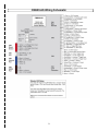
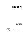
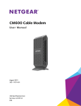
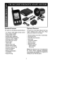
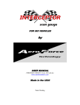
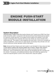
Installation Manual
By Firstech LLC, Version: 1.4
Applicable to the following alarm and remote
start system:
CM600-AS – Auto Only Starter Control
Module – F/W 3.10
This device complies with Part 15 of the FCC rules. Operation is subject to the following conditions;
(1) This device may not cause harmful interference.
(2) This device may accept any interference received, including interference that may cause undesired operation.
CAUTION: Changes or modifications not expressly approved by the party responsible for compliance could void the
user’s authority to operate this device.
WWW.COMPUSTAR.COM
Table of Contents
Introduction ............................................................................................................................................ 3
Kit(s) Contents ....................................................................................................................................... 3
Remote Code Routine(s) ....................................................................................................................... 5
Programming Remotes to CM-600AS .................................................................................................. 5
Placement and Use of Components ..................................................................................................... 5
Antenna and Cable .............................................................................................................................. 5
Hood Pin .............................................................................................................................................. 5
Shock Sensor....................................................................................................................................... 6
Siren .................................................................................................................................................... 6
Common Procedures ............................................................................................................................. 6
Valet Mode ........................................................................................................................................... 6
Jumper Settings ................................................................................................................................... 6
Diesel Timer ......................................................................................................................................... 8
CM-600AS Wiring Schematic ................................................................................................................ 9
Connector 1 (CN1), 8-Pin Ignition Harness ........................................................................................ 10
Connector 2 (CN2), 12-Pin Harness ................................................................................................... 11
Connector 3 (CN3), 8-Pin Harness..................................................................................................... 11
Connector 4 (CN4), 6-Pin Lock Harness ............................................................................................ 12
Connector 5 (CN5), 4-Pin (RS232 Port - 2 Way Data)........................................................................ 13
Connector 6 (CN6), 4-Pin (Antenna Cable) ........................................................................................ 13
Connector 7 (CN7), 2-Pin (Pre-wired LED) ........................................................................................ 13
Connector 8 (CN8), 4-Pin (Shock Sensor Port) .................................................................................. 13
Option Programming Tables ............................................................................................................... 14
Option Menu Descriptions .................................................................................................................. 16
Option Programming ........................................................................................................................... 19
Option Programming Using the FT-OP500-KIT (programmer) ........................................................... 19
Option Programming Using a Remote ................................................................................................ 19
Troubleshooting................................................................................................................................... 21
Remote Start Error Codes .................................................................................................................. 21
Alarm LED Diagnostics ...................................................................................................................... 21
Frequently Asked Questions .............................................................................................................. 22
Technical Support Contacts................................................................................................................ 24
2
Introduction
Thank you for purchasing a Firstech alarm and remote start system for your vehicle. The following
installation manual is intended for experienced and authorized mobile and alarm technicians. This is not
a tutorial on how to install. We highly recommend that you contact your local Firstech dealer and seek
professional installation.
Call 888-820-3690 or visit our website at www.compustar.com to locate your nearest dealer.
Caution: The Manufacturer’s warranty will be void if this product is installed by anyone other than an
authorized dealer. Firstech reserves installation support services to authorized dealers only.
Kit(s) Contents
The CS-700AS, CS-600AS, and CS-6102AS includes all your basic components for basic install.
-
2 x Remotes
1 x Antenna
Alarm and Starter Control Module CM600-AS
1 x Bright Blue LED
1 x Hood Pin
1 x Shock Sensor
1 x Siren
Pack of Wiring Harnesses
3
-
Installation Basics
If you are new to installing Compustar by Firstech alarm and starter units, we highly recommend that you
review this manual in its entirety prior to installing your first unit.
Key Points to Consider Before Installation:
The two included remotes are preprogrammed to the unit
Page 5
This system is designed for ease of installation and the two included remotes are preprogrammed. In the
event you may need to program new remotes cycle the ignition ON / OFF five times within seven
seconds and tap the Lock button (half second) on the first remote, and then tap the Lock button (half
second) on the second remote.
New Valet Procedure
Page 6
There are two amendments to Valet Mode. To place the system into Valet, you must hold the foot brake
and cycle the ignition 5 times. To place the system into Valet using the remote you must turn the ignition
on and then tap the Lock and Trunk buttons.
New Tach learning procedure
Page 7
To Learn Tach:
STEP 1. Start the vehicle with the key and allow it to idle down
STEP 2. Press and hold the foot brake
STEP 3. While holding the foot brake, hold the remote start button on the remote for 2.5 seconds
One parking light flash indicates that the vehicle tachometer signal has been successfully learned. Three
parking light flashes indicate that the control module failed to learn the tachometer signal
New Option Menus
Page 14
The new option menu differs completely from other Firstech systems. It is important to familiarize
yourself with these as it will save time in most applications.
Option Programmer (FT-OP500-KIT)
Page 19
Most options on this unit can be programmed with the remote(s) as well as the Option Programmer
(OP500). Please note the system must be disarmed before connecting the OP500. Otherwise, an
“ERROR” message will show on the display of your OP500. Connect the OP500 by unplugging the
antenna and plugging into the blue 4 pin port at the top of the programmer.
Updatable Firmware
The firmware on the CM-600AS can be updated through the RS232 port. Sign up on
www.firstechonline.com for instructions and exclusive dealer access
4
Remote Code Routine(s)
IMPORTANT: The included remotes are preprogrammed to the control module. In the event that you
need to program the remotes follow the instructions below.
Programming Remotes to CM600-AS
STEP 1: Activate Programming mode by turning the ignition key on and off (between the Acc & On
positions) five times within 7 seconds. The vehicles parking lights will flash once with the successful
completion of this step.
STEP 2: Within a second after cycling the ignition the 5th time, tap the Lock button on the remote for a
half second. The parking lights will flash once to confirm the transmitter has been coded.
Programming Multiple Remotes: After the confirmation flash given
in STEP 2, you can code additional remotes by tapping the Lock
button on the remote(s). The parking lights will flash once confirming
each additional remote. The CM600-AS can store up to three
remotes.
Exiting Programming: Programming is a timed sequence. If you can
not get the remote(s) to program then the system enters Valet Mode.
The parking lights will flash twice signaling the end of programming
mode.
Placement and Use of Components
IMPORTANT: The placement and use of components are
critical to the performance of this system.
Antenna and Cable
Antenna
Firstech antennas are calibrated for horizontal installation
at the top of the windshield. It does not have to be
mounted in the top left corner as shown to the left. The
cable that connects the antenna to the brain must be free
from any pinches or kinks. Installing the antenna in areas
other than the windshield may adversely affect the
effective transmitting distance of the remotes.
Hood Pin
The hood pin is an important safety feature that prevents the remote start from engaging while the hood
is open. This is also to prevent accidental injury in the event that the vehicle is in service.
5
Shock Sensor
For best results mount the shock sensor by zip tying it to the vehicle’s main ignition harness. There is a
small dial on the sensor that ranges from Off to 10. The higher the number on the dial, the greater
sensitivity of impact. A small adjustment to the dial can make a significant difference in sensitivity for both
1st and 2nd stages. Recommended dial settings for most vehicles is somewhere between 2 & 4. The
system begins monitoring the shock sensor 30 seconds after the alarm is armed.
Siren
The siren should be mounted securely in the engine bay. To adjust duration time when the alarm has
been triggered, change Option 2-08 – the system default is 30 seconds.
Common Procedures
Valet Mode
When servicing or loaning your vehicle to others, your alarm system should be placed in Valet mode.
Valet mode disables all alarm functions as well as parking lights.
IMPORTANT: While in Valet mode your remotes will still lock and unlock the doors.
The system can be put into valet one of two ways:
1. Turn the vehicle’s key to the ignition “on” position and tap the Lock and Trunk buttons
simultaneously for a half second. The parking lights will flash once to confirm the system is in
Valet Mode. Repeat this process to take the system out of Valet Mode. Ignition does not have to
be on. Upon holding the same buttons again the parking lights will flash twice to confirm the
system is out of Valet Mode.
2. You can put the system into Valet by holding the foot brake and then turning the
ignition key “on” and then “off” five times within 7 seconds. The parking lights will flash
once to confirm the system is in valet mode. Shortly after the first flash, the parking
lights will flash twice.
Jumper Settings
Caution: Jumper settings affect the polarity and use of certain outputs. If these jumpers are used
incorrectly, damage to the vehicle and control module may occur. The jumpers can be found by opening
the small door on the front of the CM600-AS.
Jumper 1 (Door Trigger Polarity)
Determines the polarity of the door trigger input wire (red/white). In the default position the door trigger
registers negative (-) triggers. To change to a positive (+) trigger, move the jumper.
Jumper 2 (2nd Ignition / 2nd Starter / 2nd Accessory Relay)
This jumper determines the behavior of the large blue wire on Connector 1. This wire is powered by an
internal relay in the control module. In the default position the jumper is set to 2nd Ignition. 2nd Ignition is
common on GM and Toyota vehicles and will need powering. You can change the behavior of the wire to
act as a 2nd Starter or 2nd Accessory to power up those wires common on newer Toyotas and Nissans.
Tachless Sensing – Default Setting on Option 2-04
Tachless sensing is an alternative engine sensing mode. Tachless sensing does not require a
connection to the vehicle other than the main ignition harness. IMPORTANT: All wiring connections must
be made before attempting remote starting.
6
STEP 1: Connect all necessary wires.
STEP 2: Process complete – there is no further programming required other than adjusting crank time
when necessary (see below).
Adjusting Crank Time: To adjust the crank times, refer to Options 1-03 and 2-05. To help ensure
successful starting, the system will automatically add additional crank time to the 2nd and 3rd start
attempts. In addition, there is a built in “Smart Resting Mode”. Traditional tach sensing is highly
recommended for colder climates.
Tach Sensing – Option 2-04 Setting 2
Tach sensing mode requires a connection made with the yellow/black wire on Connector 2. Firstech
recommends using an injector, coil or other tach source for tachometer sense. IMPORTANT: The tach
must be programmed before remote starting.
STEP 1: Start the vehicle with the key. Allow time for the engine to idle down.
STEP 2: Test wire and make connection. With the vehicle off the wire should test 0 Volts AC. At idle the
tach wire should test between 1 to 5 Volts AC. As the vehicle RPM’s increase the voltage on the meter
will also increase. Always solder tach connections.
STEP 3: Learn tach. While the vehicle is at idle, hold the foot brake and press and hold the remote start
button on the remote control for 2.5 seconds.
The parking lights will flash once to confirm a good tach signal. The parking lights will flash three times to
indicate the tach did not learn. Two seconds following the three flashes, the number of parking light
flashes will indicate the cause of the error;
Number of Parking Light
Flashes
1
2
3
Tach Error
Option 2-04 is not on setting 2
Key is in the off position
Bad tach signal. Find a different wire.
Advanced Tachless – Option 2-04 Setting 3
Advanced Tachless is an alternative method the Firstech remote start system can utilize to determine if
the engine is running. This is different than no tach sensing so the yellow/black wire connection must be
made. IMPORTANT: No programming other than option changing is required for Advanced Tachless.
STEP 1: Change Option 2-04 to setting 3 - Advanced Tachless.
STEP 2: Test wire and make connection. The stator wire is found at the vehicles’ alternator. Change
your meter to DC before testing for this wire.
A. At rest, with the ignition off, the stator wire should test 0V DC.
B. Turn the ignition to the run position. The stator wire should now test between 1 – 6V DC.
C. Start the vehicle with the key. The stator wire should now test between 12 – 14V DC at idle.
STEP 3: Process complete – no further programming is required.
Assumed Timed Crank – Option 2-04 Setting 4
Assumed Time Crank is the last feature of Option 2-04 for remote starting. This is intended for vehicles
7
with built-in anti-grind feature or vehicles that do not have a 12V Positive starter wire at the ignition
harness. This option will send a 1.5 second crank signal to the vehicle. This option can be used on
vehicles with built in anti-grind systems.
Automatic Transmission Remote Start Function
Hold the
button for 2.5 seconds to remote start an automatic transmission vehicle. If you are in
range and if the vehicle is ready to remote start, the vehicle parking lights will flash once.
If you are in range, the parking lights on the vehicle will flash three times followed by a certain number
after that, there is a remote start error. Refer to the “remote start error diagnostic” table under the
Troubleshooting section of this manual for details.
Upon receiving confirmation that your vehicle is running, the parking lights will light solid. The remote
start run time can be set for 3, 15, 25, or 45 minutes. The option is 1-08 to adjust the remote start run
time. This should be set at the time of installation.
IMPORTANT: The vehicle’s key must be inserted into the ignition and turned to the “on” position prior to
driving your vehicle. If the foot brake is depressed prior to the key inserted and in the “on” position, the
vehicle will shut off.
Diesel Timer
The CM600-AS module has a built in Diesel Timer to allow the vehicle’s glow plug wire to heat up. There
are two time settings on this unit, 7 or 18 seconds. This will allow the ignition to power up and then crank
once the time has expired and glow plugs have properly heated up. There is also a 3rd setting that will
delay the ignition for remote starting GM vehicles.
8
CM600-AS Wiring Schematic
9
Connector 1 (CN1), 8-Pin Ignition Harness
Pin 1 Red - Constant 12V positive (+) power input. This wire must be connected. The proper vehicle
wire will test (+) 12V at all times - while the key is in the off position, the on position and during
crank.
Pin 2 Green/White – This is the positive (+) parking light wire that triggers when you lock and unlock
the doors and remote start the vehicle.
Pin 3 Red/White - Constant 12V positive (+) power input. This wire must be connected. The proper
vehicle wire will test (+) 12V at all times - while the key is in the off position, the on position and
during crank.
Pin 4 White - Accessory 12V positive (+) output. This wire must be connected to the vehicle accessory
/ HVAC blower motor wire. The proper wire will test 0V with the key in the off position, (+) 12V
while key is in the on position, 0V while cranking and back to (+) 12V when the key is returned to
the on position.
.
Pin 5 Blue - Positive 12V (+) output that powers up during remote start. The behavior of this wire is
selectable by a jumper inside the control module. By default this wire powers up as a 2nd Ignition
trigger. It is changeable to a 2nd Starter or 2nd Accessory.
Pin 6 Yellow - Starter 12V positive (+) output.
This wire must be connected for remote
start. The proper wire will test 0V with
the key in the off position, 0V while the
key is in the on position and (+) 12V
during crank. This wire will be
connected to the starter kill/anti grind
relay at pin 87A.
There are two wires coming off of the
relay; yellow/black and yellow. To utilize
the anti-grind or starter- kill features, the
vehicle's starter wire must be cut in half,
otherwise, cut the relay out of the
harness and connect the yellow (Pin 6)
directly to the vehicle's starter wire. The
starter kill/anti grind relay has a thin 24
gauge blue wire. This must be
connected to pin 2 (24 gauge blue wire)
on Connector 3.
IMPORTANT: For anti-grind and starter-kill applications, the yellow wire goes to the starter side
of the vehicle's starter wire and the yellow/black goes to the key side.
Pin 7 Green – Ignition 12V positive (+) output and input. This wire must be connected to the vehicle's
ignition for remote start and valet / remote programming. The proper wire will test 0V with the key
in the off position, 12 V (+) while the key is in the on position and 12V (+) during crank. This pin
will also have an additional wire connected to the starter kill/anti grind relay.
Pin 8 Black - Ground negative (-) input. This wire must be connected to the vehicle’s ground.
10
Connector 2 (CN2), 12-Pin Harness
Pin 1 Green/White – This is the negative (-) parking light wire that triggers when you lock and unlock
the doors and alarm goes off. The proper wire will test (-) when the parking light switch is in the
on position.
Pin 2 Red/Black – 2nd Starter 250mA negative (-) output. This output can be used to trigger a relay to
power a 2nd Starter wire on the vehicle – common on newer Toyotas and Nissans.
Pin 3 White/Black - 2nd Accessory 250mA negative (-) output. This output can be used to trigger the
pre-wired relay located on the main ignition harness.
Pin 4 Black – Status/Ground while running 250mA negative (-) output. This is an optional output that
will provide a negative (-) output before the ignition cranks and stay on throughout the remote
start duration. This wire is most commonly used to trigger bypass / transponder modules.
.
Pin 5 Orange - Factory Arm 250mA negative (-) output. This is an optional output that will provide a (-)
pulse during lock, after crank and again after the ignition shuts down.
Pin 6 Orange/White - Factory Disarm 250mA negative (-) output. This is an optional output that will
provide a (-) pulse during unlock and prior to the ignition turning on.
Pin 7 White - Horn honk 250mA negative (-) output. This is an optional output that will pulse the factory
horn. The proper wire will show ground (-) while the horn is sounding.
Pin 8 Gray/Black – Instant negative (-) trigger input. This input looks for a ground (-) input when the
system is armed/locked. Once it detects a (-) negative signal it will trigger the full alarm.
Pin 9 Light Blue/White - Brake 12V positive (+) input. This input must be connected as it provides a
shut down for the remote start. The proper wire will test (+) 12V while the foot brake is pressed.
Pin 10 Red/White – This wire is a (-) pulse input for triggering the remote start sequence. This wire
allows you to use the CM-600AS as a slave remote starter that can be controlled by a factory
OEM remote.
Pin 11 Red - This wire is a (+) pulse input for triggering the remote start sequence. This wire allows you
to use the CM-600AS as a slave remote starter that can be controlled by a factory OEM remote.
Pin 12 Yellow/Black - Engine sensing input. This wire is connected to the vehicle’s Tach wire and is
required if you are not using the tachless sense setting. IMPORTANT: To change enginesensing modes, you must change Option 2-04:
Connector 3 (CN3), 8-Pin Harness
Pin 1 Brown - Siren 12V positive (+) output. Connect this wire to the red (+) wire located on the siren.
To change siren output settings, review Option 1-05.
Pin 2 Blue – Ground when armed output. This wire sends a (-) negative output when the alarm is
armed. It triggers the starter kill/anti grind relay for the CM-600AS. It can also be used for other
11
options like window roll-up. Make sure to connect this to the blue wire on the starter kill/anti grind
relay.
Pin 3 Red/White - Door trigger input. This wire requires negative (-) or positive (+) trigger door-pins.
The proper wire provides a (-) or a (+) trigger only when the doors are opened. You will need to
test the wire for proper polarity and set the jumper inside the CM-600AS for the corresponding
polarity.
Pin 4 Violet/Black - Trunk negative (-) input. This is an optional input that will monitor when the
vehicle’s trunk has been opened. The proper wire will provide a (-) trigger while the trunk is open.
Pin 5 Gray/White - Auxiliary Trigger Input 1 – This wire functions as a negative (-) pre-warn input. It is
selectable based on option 3-06. It can be changed to a negative arm, negative ignition, negative
instant trigger or negative closed loop trigger input. Please refer to the option tables for details.
Pin 6 Black/White - Auxiliary Trigger Input 2 – This wire functions as a negative (-) instant trigger input.
It is selectable based on option 3-07. It can be changed to a negative disarm, negative key sense
or negative parking light reminder input trigger. Please refer to the option tables for details.
Pin 7 Yellow - Auxiliary 1 Output – This wire provides a customized timed output for triggering extra
sensors and/or features such as power sliding doors or power windows. The settings can be
changed via option 3-02. To set a custom timed output you must use option setting 4 as well as
an OP500 Option Programmer.
Pin 8
Yellow/White - Auxiliary 2 Output – This wire provides a customized timed output for triggering
extra sensors and/or features such as power sliding doors or power windows. The settings can be
changed via option 3-03. To set a custom timed output you must use option setting 4 as well as
an OP500 Option Programmer.
Connector 4 (CN4), 6-Pin Lock Harness
Pin 1 Not used
Pin 2 Violet/White - Trunk release 250mA negative (-) output. This is an optional output that will
release the trunk. System will unlock doors and disarm alarm prior to trunk release.
Pin 3 Orange/Black – 2nd Pulse Unlock wire. This wire is used to provide the customer with a driver’s
priority unlock feature with option 1-04. With the option on the unlock (blue) wire will pulse first
and then orange/black will pulse if the unlock button is pressed again within 3 seconds.
Pin 4 Blue - Unlock 250mA negative (-) output. This is an optional output that will provide a (-) pulse for
unlocking doors. System will unlock doors and disarm alarm. IMPORTANT: You must use
relays or DM600 or DM700 to reverse polarity for (+) trigger door lock systems.
Pin 5 Blue/Black - Lock 250mA (-) negative output. This is an optional output that will provide a (-)
pulse for locking doors. System will lock doors and arm alarm. IMPORTANT: You must use
relays or DM600 or DM700 to reverse polarity for (+) trigger door lock systems.
Pin 6 Not used
12
Connector 5 (CN5), 4-Pin (RS232 Port - 2 Way Data)
Pin 1 Red - Constant 12V positive (+) output.
Pin 2 Black - Negative (-) ground This wire transmits the signal to remote.
Pin 3 RX input
Pin 4 TX output
Connector 6 (CN6), 4-Pin (Antenna Cable)
Pin 1 Yellow - RX input. This wire receives the signal from remote.
Pin 2 White - TX output. This wire transmits the signal to remote.
Pin 3 Red – Constant 12V positive (+) output.
Pin 4 Black – Negative (-) ground.
Connector 7 (CN7), 2-Pin (Pre-wired LED)
Pin 1 Black - L.E.D negative (-) ground.
Pin 2 Black/White- L.E.D. 3V positive (+) output.
Connector 8 (CN8), 4-Pin (Shock Sensor Port)
Pin 1 Black - Negative (-) ground.
Pin 2 White - 2nd stage negative (-) input. (Instant trigger)
Pin 3 Red - 12V positive (+) output.
Pin 4 Yellow - 1st stage negative (-) input. (Warn away)
13
Option Programming Tables
IMPORTANT: System must be unlocked before you can set options with the OP500 or remotes.
Feature
Default Setting - I
Optional Setting II
Optional Setting III
Optional Setting IV
1-01
Unlock Before, Lock After Starting
Off
On
Lock After Start
Only
Lock After
Shutdown Only
1-02
Lock/Unlock Pulse Duration
0.8 sec
2.5 sec
0.125 sec
3.5 sec
1-03
Double Pulse Locks
Off
Unlock
Lock
Both
1-04
Driver’s Priority Unlock
Off
On
1-05
Double Pulse Disarm
Standard
Double Pulse
1-06
IGN+ACC Pulse with Disarm
Off
On
1-07
Remote Start Runtime
15 Min
25 Min
45 Min
3 Min
1-08
Auto Rearm
Off
30 Seconds
60 Seconds
5 Minutes
1-09
Passive Arming
Off
On
Passive Without
Locks
1-10
Trunk Output Timing
1 sec
0.5 sec
2 sec
Program → Aux 3
1-11
Unlock/Disarm with Trunk Release
Unlock, Factory
Disarm, and Trunk
Release
Factory Disarm,
Trunk Release Only
Trunk Release Only
Aux 3
1-12
Dome Light Delay
Off
5 Seconds
45 Seconds
Auto
1-13
Trigger Start
Triple Pulse
Double Pulse
Single Pulse
Feature
Default Setting - I
Optional Setting II
Optional Setting III
Optional Setting IV
2-01
Timer Start
3 hour
1.5 hour
2-02
Minimum Crank Time w/ Tachless
Mode
0.8 or 1.0 sec by
feature 2-05
1.4 sec
2-03
Ignition Locks
Off
On
Ignition Lock Only
Ignition Unlock Only
2-04
Engine Sensing
Tachless
Tach
Alternator
3 sec Start Assume
Running
2-05
Minimum Crank Time w/Alternator
Sensing
0.8 sec
1.0 sec
0.6 sec
2-06
Diesel Timer
OFF
7 sec
18 sec
Delayed Ignition
(GM)
2-07
Rearm Output
1st lock after start
and after shutdown
1st lock, shutdown
After Start Only
After Shutdown
Only
2-08
Siren Duration
30 Seconds
60 Seconds
120 Seconds
Chirp for 20
Seconds
2-09
Siren Output
On Lock, Unlock,
and Start
On Double Lock
On Lock and Unlock
Alarm Only
2-10
Horn Output
On Double Lock
On Lock and Unlock
On Lock, Unlock,
and Start
Alarm Only
2-11
Horn Honk
Pulsed
Latched
2-12
(-) Ground When Armed
Starter Kill + AntiGrind
Latched when
armed
20 Seconds
Program → Aux 4
14
2-13
Advanced Tachless
Off
On
Feature
Default Setting - I
Optional Setting II
Optional Setting III
3-01
Secure Aux Output
On
Off
On While Armed
3-02
Aux 1 Output
0.5 Second
Latched
20 Seconds
Program
3-03
Aux 2 Output
0.5 Second
Latched
60 Seconds
Program
3-04
Aux 1 Output Control
By Remote
Arm
Disarm
Ignition Off
3-05
Aux 2 Output Control
By Remote
Arm
Disarm
Start
3-06
Auxiliary Input 1 (Grey/White)
(-) Pre-Warn
(-) Arm
(-) Closed Loop
3-07
Auxiliary Input 2 (Black/White)
(-) Trigger
(-) Disarm
(-) Key Sense
3-08
Shock Sensor Inputs
1st Stage: Prewarn
2nd Stage: Instant
1st Stage: Disable
Arm/Disarm
2nd Stage: Instant
1st Stage Input:
Prewarn
2nd Stage: Disable
Arm/Disarm
3-09
Sliding Door (Aux 1, Aux 2) Control
for iDatalink Modules
Off
Unlock, Factory
Disarm, and Sliding
Door Control
Factory Disarm and
Sliding Door Control
Only
3-10
Soft Disarm
Off
On
3-11
Siren/Horn Mute Control on Remote
Disabled
Enabled
Feature
Default Setting - I
Optional Setting II
Optional Setting III
4-01
Connector 2 Pin 1 (Green/White)
Parking Lights
Ignition
Accessory
4-02
Connector 2 Pin 3 (White/Black)
Accessory
Ignition
Start
Feature
1
Aux 1 Output
2
Aux 2 Output
3
Aux 3 Output
4
Aux 4 Output
Optional Setting IV
(-) Ignition, Instant
Trigger & Shock
Sensor Bypass
(-) Parking Light
Reminder
Optional Setting IV
Setting Value (Seconds)
1-99
*Once programmed, this feature requires activation from the remote. Please refer to the
remote user manual or the option description below.
15
Option Menu Descriptions
1-01
Unlock Before, Lock After Starting - If enabled, this option will unlock the doors before remote
starting, start the vehicle, then lock the doors after the vehicle starts. It will then lock the doors
again if the remote start run time expires and the vehicle shuts down. The third option locks the
doors upon remote start shut down only. The fourth option turns on lock after remote start
shutdown only. This feature is for vehicles that have factory alarms that need to be disarmed
before remote starting such as Toyota and Lexus.
1-02
Lock / Unlock Pulse Duration – This option changes the length of the lock and unlock ground
pulses on the blue and blue/black wires on CN4. The default setting is for 0.8 seconds. Optional
setting 2 changes the duration to a 2.5 second pulse. The third setting changes the duration to a
short 0.125 second pulse setting. The fourth setting changes the duration to a 3.5 second pulse.
1-03
Double Pulse Locks – This option pulses the unlock (blue) wire twice to unlock all doors or
disarm the factory alarm on some vehicles. This feature cannot be used with Option 1-04.
1-04
Driver’s Priority Unlock – This lets you use the CM-600AS to unlock the driver’s door before the
rest of the doors as in some factory systems. The user has the hit the unlock on the remote a
second time to unlock the rest of the doors. The driver’s door must be isolated from the other
doors. Use the Orange/Black CN4 as your 2nd Unlock output.
1-05
Double Pulse Disarm Wire – This feature turn the disarm wire into a double pulse output for
shutting down factory alarm outputs.
1-06
IGN + ACC Pulse with Disarm – This option will pulse the ignition and accessory wires on CN1
at the same time the disarm wire pulses. Most newer Ford/Lincoln/Mercury vehicles need the
ignition and accessory pulsed to disarm the factory alarm.
1-07
Remote Start Runtime – This option changes the remote start run time from its default 15
minutes to 25, 45, or 3 minutes.
1-08
Auto Rearm – The system will automatically rearm and relock if there is no activity on the (green)
ignition wire or (red/white) door trigger wires. See the option table for available settings.
1-09
Passive Arming – This option must be set to 2 before you can turn Passive Arming on with the
remote. Passive Arming will happen only after the door is opened and closed. Simultaneously tap
the Unlock + Trunk buttons on the remote for a half second to activate passive arming. The
parking lights will flash once to indicate this feature is ON.
1-10
Trunk Output Timing – This option sets the output duration of the violet/white wire on CN4. The
available options are 1, 0.5, and 2 seconds. You must set the fourth option if you have option 111 on setting 4.
1-11
Unlock/Disarm With Trunk Release – This option has 4 settings. The settings are self
explanatory but option 4 turns the trunk release wire (violet/white) on CN2 into an Auxiliary 3
which is also programmable via the OP500.
1-12
Dome Light Delay – This option is used when connecting the door trigger input to the vehicles
dome light circuit. It delays the door trigger input to prevent the door open notification. Please
see the option table for available settings.
16
1-13
Pulse Trigger – This option changes the amount of pulse trigger(s) needed to active the control
module as a slave unit. The default setting requires two ground or 12V+ pulses to activate.
Setting 2 changes the trigger to a triple ground or 12V+ pulse. Setting 3 changes the trigger to a
single ground or 12V+ pulse to activate the remote start sequence.
2-01
Timer Start or Interval Between Cold Start - This option dictates the time interval when the
control module will remote start.
Default 1: Will start every 3 hours until the vehicle is remote started or started by key and run for
the set run time in option 1-08.
Option 2: Will start every 1.5 hours until the vehicle is remote started or started by key and run
time in option 1-08.
2-02
Minimum Crank Time With Tachless Mode – This option will increase the standard crank time
from 0.8 seconds to 1.4 seconds when remote starting. Please keep in mind that the crank time
will increase with each try.
2-03
Ignition Controlled Locks – When you turn this option on and have the power door locks
connected, the doors will lock when you remote start or start the vehicle with the key and then
press the foot brake. When you turn the key off the doors will unlock if this feature is turned on.
The feature also requires activation from the remote. Simultaneously tap the Lock + Remote Start
buttons for a half second to activate ignition controlled door locks from the remote. The parking
lights will flash once to indicate this feature is ON.
2-04
Engine Sensing – This module comes default in Tachless mode where it does not require a tach
connection. Setting 2 changes to the tach sensing where you will need to connect to a wire that
tests as a tach. Setting 3 changes the mode to alternator sensing it does not require a tach
connection. Setting 4 does an assumed start feature where the control module will automatically
crank the yellow starter wire for 1.5 seconds. Please see the “Common Procedures” section on
page 6-7 of this manual for complete explanations on the four engine sensing modes.
2-05
Minimum Crank Time With Alternator Sensing – This option will increase the standard crank
time from 0.8 seconds to 1.4 seconds when remote starting. Please keep in mind that the crank
time will increase with each try.
2-06
Diesel Timer – Use this option when installing on Diesel motors. You can use setting 2 and 3 for
a default wait-to-crank; otherwise, you can adjust the time with your OP-500 Programmer.
2-07
Rearm Output - This option will change the behavior of the orange wire on CN2. This wire is
used for triggering the factory alarm or shutting the RAP system off.
2-08
Siren Duration – The default setting for the siren output upon panic or alarm trigger is 30
seconds. You have the ability to extend that with this option. Please see the option tables for
other available settings.
2-09
Siren Output – The brown wire on CN3 can be changed to output a pulsed (+) 12V output.
2-10
Horn Output – This option sets the behavior of the horn wire during alarm state, during double
lock from the remote or during lock and unlock from the remote. During one of the options the
event will send a negative pulse on the white wire on CN2.
2-11
Horn Honk – This option sets the duration of the output on the horn (white) wire. At default it will
pulse depending on option 2-10. At the optional setting it will latch a ground trigger to use for
triggering another siren.
17
2-12
Ground When Armed – Ground When Armed or GWA, at default setting will send a constant
latched negative output when armed and remote started on the blue wire on CN3. This is used to
trigger your starter kill relay and prevent overgrinding on the vehicle's starter. The optional setting
turns the output into a latched GWA only. Optional setting 4 will make the blue wire an Auxiliary 4
which is programmable by your OP500 Option Programmer.
2-13
Advanced Tachless - This feature when used in conjunction with feature 2-04 option 3 will
provide an enhanced Tachless engine sensing mode.
3-01
Secure Aux Output – On the default setting, trunk and star buttons must be held for 2.5 seconds
before Aux 1 or Aux 2 can be triggered. This prevents accidental triggering of the outputs. Option
setting 2 turns this feature off.
3-02
Aux 1 Output - This option determines the duration of the Aux 1 output. Setting 4 allows the
output duration to be set for a specific length of time.
3-03
Aux 2 Output - This option determines the duration of the Aux 2 output. Setting 4 allows the
output duration to be set for a specific length of time.
3-04
Aux 1 Output Control – This option sets the condition which controls Auxiliary 1 and how it is
triggered. Please see the option table 3 for details.
3-05
Aux 2 Output Control - This option sets the condition which controls Auxiliary 2 and how it is
triggered. Please see the option table 3 for details.
3-06
Auxiliary Input 1 – This option changes the input condition on the gray/white wire on CN3.
Default 1: Will pre-warn with a negative (-) ground input.
Option 2: Will arm the system with a negative (-) ground input. Used when adding an alarm to a factory keyless entry
system.
Option 3: Turns the wire into a closed loop trigger. Can be used to detect if the circuit is broken like for a trailer
connected to the truck hitch.
Option 4: Turns the wire into a (-) ignition input that bypasses the instant trigger wire and shock sensor.
3-07
Auxiliary Input 2 – This option changes the input condition on the black/white wire on CN3.
Default 1:. Will instant trigger with a negative (-) ground input.
Option 2: Will disarm the alarm with a negative (-) ground input. Used when adding an alarm to a factory keyless entry
system.
Option 3: Turns the wire into a (-) Key Sense wire. If the wire sees a negative trigger it will not allow the system to arm.
Option 4: Turns the wire into a (-) Parking Light Reminder input. If the wire sees a negative trigger during arm it will
chirp the siren and flash parking lights 5 times to notify the user that their parking lights are still on.
3-08
Shock Sensor Inputs – This option changes the behavior of the 1st Stage or 2nd Stage input
wires. When Option 2 or 3 is set and the system is armed or disarmed and sees ground on either
wire, the CM600-AS will not arm or disarm.
4-01
Connector 2, Pin 1 - This option will change the behavior of the green/white wire on Connector 2
(CN2). At default the wire will act as negative parking light output but can be changed to (-)
accessory or ignition.
4-02
Connector 2, Pin 3 - This option will change the behavior of the green/white wire on Connector 2
(CN2). At default the wire will act as negative parking light output but can be changed to (-)
accessory or ignition.
18
4-03
ADS or Fortin - This option selects between the ADS iDatalink or Fortin bypass modules. Not all
options may be supported on this port. In that event you will have to hardwire some connections
between the bypass module and the CM-600AS.
Special Option Menu
This option menu will change the time output of Auxiliaries 1 through 4 on the CM-600AS. You must
have the FT-OP500-KIT to adjust time outputs.
Option Programming
Once you determine what options you need after install you will need to program them with either your
remote or the OP500 Option Programmer. Below are instructions on how to set the options.
Option Programming Using the FT-OP500-KIT (programmer)
The FT-OP500-KIT can be used to program all options at the same time.
STEP 1: Make sure system is unlocked/disarmed.
STEP 2: Using the blue connector on the top of the OP500, connect it to the control module via the
antenna wire. (Use the included extension cable if necessary.) Once connected, the OP500 will power up
as long as the main ignition harness to the controller has been connected properly.
STEP 3: To change the option number you wish to program, use the left and right arrow keys on the
OP500. It will scroll through the options available in menu 1 and then move to menu 2. Use the up and
down arrow buttons on the OP500 to adjust the option settings; “1” is the default setting, and “2”, “3”, and
“4” are the optional settings.
STEP 4: When finished with the adjustment of the various option settings, press and hold the “W” (write)
button for 3 seconds. This will write the settings to the control module. Wait until the module displays
“Success Good” before disconnecting it from the antenna cable.
To reset the options, hold the “R” (reset) button and the “W” (write) button for 3 seconds. Release then
write the reset, hold the “W” button for 3 seconds.
Option Programming Using a Remote
Using a remote is a timed process so please thoroughly review this section before programming. You
must program each option one at a time.
STEP 1: Make sure system is unlocked/disarmed with remote.
STEP 2: Use this table below to select your option in its specific menu:
19
Option
Menu 4
Tap
Lock
Button
Tap
Unlock
Button
Tap
Trunk
Button
Select
Option 4
Select
Option 3
Option
Menu 3
Tap
Key/Start
Button
Select
Option 2
Option
Menu 2
Lock + Unlock for 2.5
seconds then Lock +
Unlock for 2.5 seconds
Lock + Unlock for 2.5
seconds then Lock +
Key/Start for 2.5
seconds
Lock + Key/Start for
2.5 seconds then Lock
+ Unlock for 2.5
seconds
Lock + Key/Start for
2.5 seconds then Lock
+ Key/Start for 2.5
seconds
Select
Option 1
Option
Menu 1
Scroll
Through
Menu
Wait for corresponding parking light flash and/or
siren chirp before selecting the option
Entering
Option Menu
(Wait for
chirp
between
button hold)
How To Program CM600-AS Options With Remotes
Tap
Key/Start
Button
STEP 3: Once the system confirms the option number, set the option to the desired setting by tapping
the Lock, Unlock, Trunk, or Start buttons. The Lock button is Option 1, Unlock button is Option 2, Trunk
button is Option 3, and Start button is Option 4.
Resetting to Factory Defaults: To reset the options in a particular menu group, enter the menu by
following the table above, then tap the Start button three times. The parking lights will flash after each
tap. After the third tap, the option menu will reset, siren chirps and parking lights flash three times. This
must also be done for Menu 2, 3, and 4.
20
Troubleshooting
Remote Start Error Codes
If the remote start fails to start the vehicle, the parking lights will flash three times immediately. Following
those three flashes the parking lights will flash again corresponding to the error table;
Number of
Parking Light
Flashes
Remote Start Error
Motor running | or | must program tach
before 1st remote start
Ignition on | or | foot brake on
Foot brake on
Hood open
Remote start failure
System is in Valet Mode
1
2
5
6
8
10
Alarm LED Diagnostics
When the alarm is triggered the LED (if installed) will flash a certain amount of times as shown in the
table below.
Priority
1
2
3
4
Trigger
Door/Hood/Trunk/Ign
Triggered
2nd Shock Triggered
2nd
LED Flash Diagnostic
2 flashes, rest, then repeat
3 flashes, rest, then repeat
Auxiliary Input
Triggered
4 flashes, rest, then repeat
Panic with remote
5 flashes, rest, then repeat
21
Frequently Asked Questions
I have everything hooked up and the system will not respond.
A: Check all your wires to the control module. Next check your fuses and ground. If the system does not
respond after that then try programming the remotes. Please see the “Common Procedure” section of
this manual for remote programming instructions.
Can I use any other CompuStar remotes on this system?
A: Yes you may use any other 4 Pin Antenna RF Kit in the Firstech lineup.
I am trying to program options with the OP500 Option Programmer and it flashes “ER 01” when I
plug it in to the antenna cable. What should I do?
A: First, make sure all connections are made to the control module. Second, make sure that the system
is not locked. The last thing to check is the antenna cable or antenna extension cable – make sure this is
not damaged. If you need to, try another cable. When the OP500 is working properly, it will read
“Success Good.”
Is the CM-600 compatible with Manual Transmission vehicles?
A: No, the CM-600 remote start system is compatible with Automatic Transmission vehicles only.
What is the thick blue wire on CN1 and the jumper in the control module?
A: This wire is ran to an internal relay on the control module. This wire can be used to power up a 2nd
Ignition, 2nd Starter, or 2nd Accessory wire on the vehicle. The behavior of the wire is changed by the
internal jumper in the control module.
How do I set the auxiliaries?
A: The CM-600AS has programmable auxiliary outputs. You have four preset timed options to program
your auxiliaries for. You must have an Option Programmer (FT-OP500-KIT) to set a specific time output
for the auxiliaries. Please see the Option Tables in this manual for details.
All my connections are made, how do I program the tach?
A: Start the vehicle with the key. Hold the foot brake down. While holding the foot brake down hold the
Key/Start button down for 2.5 seconds. If the system flashes the parking lights once then the tach is
programmed. If it flashes three times, pause and then a certain amount please review the “Common
Procedures” section of this manual.
The vehicle starts and shuts down 3 times in a row.
A: This usually means that the engine sensing mode is not working correctly. If you are using a coil,
change to an injector or try alternator mode. If you are using the tachless sensing mode and it does not
start check the two power wire on the control module. If it does not remote start you may try setting 4
assume start otherwise the only alternative is finding a tach or alternator sense wire.
The vehicle will lock and unlock, but will not flash the parking lights or chirp the siren.
22
A: The system is in valet mode. Tap the Lock and Trunk Buttons and the same time for 0.5 seconds to
exit Valet Mode. If that does not work try reprogramming the remotes again.
Whenever I try to arm the vehicle, it chirps the siren 3 times and will not arm.
A: Check all the trigger input wires for ground.
Do the door locks flip-flop in polarity?
A: No. You can use the DM700 (relay pack) for high current positive (+) locks, or the DM600 harness
used for low current 600mA positive (+) locks. If those are not available you must use two SPDT relays
to invert the polarity.
.
23
Technical Support Contacts
Firstech technical support is reserved for authorized dealers only.
Monday - Friday
888-820-3690
(8:00 am – 5:00 pm Pacific Standard Time)
Email
[email protected]
Web
techfeed.compustar.com
Wiring Diagrams
Go to www.firstechonline.com to access Computech3. If you are an
authorized dealer and unable to access this site please contact your sales
rep or us call 888-820-3690 Monday through Friday, 8 am to 5 pm Pacific
Standard Time.
24