1
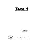
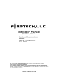
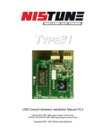
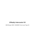
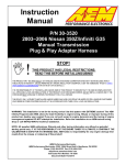
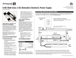
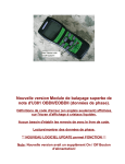
75mm Big Bore Throttle Body Kit
Installation Procedure
2003 - 2006 350z
2003-2007 G35 Coupe
2003-2006 G35 Sedan
2002-2008 Maxima
2002-2006 Altima 3.5L
Instructions can also be used for most other Nissans with the VQ35DE motor
Disclaimer: This kit should only be installed by a qualified mechanic. If you decide to do the install
yourself, please read everything and make sure you understand everything before beginning. NWP
Engineering is not responsible for the content of these instructions. This write-up is to be used only as
a guideline to help you during the installation process. Refer to the correct Factory Service Manual for
the most accurate and up to date information. NWP Engineering shall have absolutely no liability
relating to the use, non-use, improper use, installation or removal of this product. This product is not
intended for use on public roads and is not DOT approved. Please use common sense and ask a
qualified mechanic if you have any questions. Also, feel free to contact us if you need help!
CAUTION: DO NOT attempt to open the electronic throttle body
plate manually with your fingers!
This can result in a misalignment of the throttle body and can prevent the engine from
idling properly.
CAUTION: Hood clearance may be an issue with the 350z and G35 if you have an
aftermarket hood and/or have a 1/2” or thicker intake plenum spacer that raises the height
of your intake manifold. We measured over a 1/2” of hood clearance with the stock hood
on both the 350z and G35, which did not have a plenum spacer installed.
DO NOT SLAM YOUR HOOD IF CLEARANCE MAY BE A CONCERN!
Pic 1
(350z shown)
Note: You can simply measure hood clearance with modeling clay or something similar in consistency.
Apply the clay to the upper most point of your throttle body and slowly shut the hood fully allowing it to
click without slamming the hood shut. Open the hood and measure the indentation of the clay to give
you an accurate measurement for hood clearance.
Note: This adapter plate is designed to be installed using the provided NWP Engineering Port Matched
Gasket and the OEM throttle body gasket. Permatex 1 Minute Gasket (Item #25229) may be used
instead of the OEM throttle body gasket, especially if the NWP Engineering 1/4" thick Thermal Throttle
Body Spacer is installed. The provided NWP Engineering Port Matched Gasket has been extensively
tested to handle high boost applications (i.e. 40+psi of manifold pressure to be exact). But, for the best
seal for heavily modified forced inducted engines, Permatex 1 Minute Gasket (Item #25229) may be
used to replace this gasket, but it not recommended unless you are experiencing boost leaks due to
this gasket.
Note: This adapter plate has also been designed to complement the NWP Engineering Thermal Intake
Spacers. The correct length self-locking bolts have been included in your kit based on your selection at
the time of purchase. If you do not have the correct length bolts to suit the 1/4" thick Thermal Throttle
Body Spacer, please contact us and we will be happy to assist you.
Pic 2
(350z shown)
Tools Needed: Basic Metric Socket Set, 5mm Metric Allen Socket, Pliers, and Torque
Wrench that reads in “in-lbs”.
Estimated Labor Time: less than 30 minutes
1) Unplug negative battery cable
2) Remove engine cover. Disconnect MAF connector. Disconnect breather hose from intake tube.
Then remove entire intake tube from Throttle Body (TB) (Pic 1)
3) Unplug the Drive-By-Wire Electronic Throttle Body connector
4) Remove the throttle body (TB) from the manifold by removing the 4 socket head cap (SHC) bolts
with 5mm allen wrench (Pic 2)
Note: If a 1/4” NWP Engineering Throttle Body Spacer is already installed, you may need to scrape off
existing RTV on that one side of the Spacer that’s exposed. Try not to remove the Spacer if it’s firmly
stuck to the intake manifold. Less work for you to do! Then, apply a paper thin layer of Black RTV to
the Spacer or intake manifold. Or you may use an OEM TB Gasket instead.
5) Using either the stock gasket or Black RTV, install the NWP Engineering Adapter Plate (NWP logo
facing up) using the 4 provided self-locking SHC bolts. Be sure to line up the Adapter Plate to provide
the best airflow possible. (Pic 3)
Pic 3
(Maxima shown w/ TB Spacer)
Note: Due to the self-locking patch on the threads, these bolts may be difficult to thread in by hand. This is normal. A small ratchet or allen wrench may need to be used.
Be careful not to over tighten. Also, each self-locking bolt can be used up to 15 times.
CAUTION: Do not confuse “ft-lbs” with “in-lbs”!
Damage to expensive parts can result!
© 2014 NWP Engineering, Inc. – All Rights Reserved
6) Tighten the 4 self-locking bolts to 5 to 7 ft-lb
(60-84 in-lbs) in numerical order as shown. (Pic 4)
Check all bolts at least 2 times in numerical order
to confirm proper torque! Wipe away any RTV that
may have squeezed out in the airflow.
7) Using the provided 6x50 SHC throttle body bolts
with lock washer and the provided gasket, install
the 75mm Throttle Body and tighten bolts to 5 to 7
ft-lb (60-84 in-lbs) using the same numerical
pattern as shown. (Pic 4) (Pic5)
Note: If you did not purchase your 75mm TB from
us, you may need to slightly bend the left coolant
fitting upward to clear the valve cover on the 350z
and G35. All of the 75mm Throttle Bodies we sell
are guaranteed to fit and are cleaned and polished
by hand.
Pic 4
Note: On the 05-06 Altima and 04-06 Maxima, the
75mm TB should be installed with coolant lines
facing up due to clearance with the firewall and/or EGR valve. Also, the NWP Intake Spacer Kit is
required if you have the stock EGR valve installed.
Pic 5
(02-03 Maxima shown w/ Spacers)
8) Install the VoltageDrop.net Plug & Play Adapter Wire Harness between the stock TB connector and
the new 75mm TB making sure each connector firmly clicks into position. (Pic 6)
9) Install the intake tube on the 75mm Throttle Body. Fitment may be snug with the FWD Maxima
coupler. But the stock couplers on both the RWD and FWD VQ35DE engines can be used. Make
sure the adapter wire harness is underneath the intake tube and not on top.
Note: If fitment is difficult with the FWD coupler or an aftermarket coupler, you may need to remove
the coupler from the stock resonator or tube as shown (Pic 7) to install by itself then attach the rest of
the tube after. You may warm up the coupler to make it more flexible by putting it in direct sunlight,
submerging it in hot water for several minutes, or using a heat gun being very careful not to melt the
rubber. A thin coating of motor oil will help it slide onto the TB easier using two hands as shown (Pic
8). Also, a larger hose clamp may be required depending on your application.
10) Once the entire intake tube and MAF sensor housing is connected to TB, plug in the MAF
connector, connect the breather hose to the intake tube, connect the battery and that’s it!
Pic 6
Note: The coolant lines on the new 75mm TB will remain open. They are not needed since coolant
lines already exist just behind the TB on the 350z/G35 and Maxima/Altima intake manifold.
Note: If you experience a high or
erroneous idle or any drivability
issues, then perform all three
procedures below. A stopwatch or
clock with second hand will be
needed to ensure you adhere to the
proper timing specified in the
directions below, especially with the
Idle Air Volume Learning Procedure!
Accelerator Pedal Released Position
Learning Procedure
1)
Make sure the accelerator pedal
is fully released.
2)
Turn ignition switch ON and wait
at least 2 seconds.
3)
Turn ignition switch OFF and
wait at least 10 seconds.
4)
Turn ignition switch ON and wait
at least 2 seconds.
5)
Turn ignition switch OFF and
wait at least 10 seconds.
Pic 7
(Maxima Shown)
Throttle Valve Closed Position Learning Procedure
1)
Make sure that accelerator pedal is fully released.
2)
Turn ignition switch ON.
3)
Turn ignition switch OFF and wait at least 10 seconds. Make sure the throttle valve moves during
the above 10 seconds by confirming the operating sound.
Idle Air Volume Learning Procedure
Before performing this procedure, make sure that all of your electronics are OFF including your radio, headlights,
all interior lights, AC, AC/Heater Fan, rear defroster, and any aftermarket electronics such as speaker amplifiers,
power inverters, and cell chargers.
Also, make sure these conditions are met if you are having problems successfully doing this procedure:
Battery Voltage: More than 12.9V (at idle)
Engine Coolant Temp: 158-212 degrees F
Automatic Shifter: In Park
Steering Wheel: Straight Ahead Position
Vehicle Speed: Stopped
Transmission: Warmed-up (usually requires a 10 minute drive)
1)
Start engine and warm it up to normal operating temperature.
2)
Turn ignition switch OFF and wait at least 10 seconds.
3)
Confirm the accelerator pedal is fully released, turn ignition switch ON and wait 3 seconds.
4)
Repeat the following procedure quickly 5 times within 5 seconds.
1)
Fully depress the accelerator pedal.
2)
Fully release the accelerator pedal.
5)
Wait 7 seconds, fully depress the accelerator pedal and keep it for approx. 20 seconds until
the MIL stops blinking and turned ON.
6)
Fully release the accelerator pedal within 3 seconds after the MIL turned ON.
7)
Start engine and let it idle.
8)
Wait 20 seconds.
9)
Rev up the engine two or three times and make sure that the idle speed is normal (550-725
rpm).
© 2014 NWP Engineering, Inc. – All Rights Reserved
Pic 8
(02-03 Maxima Shown)