1
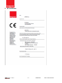
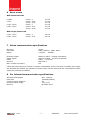
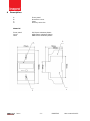
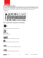
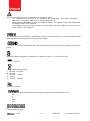
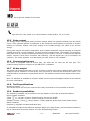
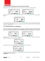
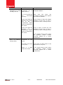
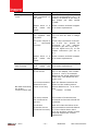
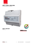
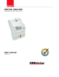
PRO370D DIN rail three phase four wire energy meter User manual Version 1.10 1 Safety instructions ............................................................................... 3 2 Foreword ............................................................................................ 4 3 CE certificate ....................................................................................... 5 4 Performance criteria ............................................................................. 6 5 Specifications ...................................................................................... 6 6 Basic errors ......................................................................................... 7 7 M-bus communication specifications ....................................................... 7 8 Far Infrared communication specifications ............................................... 7 9 Description.......................................................................................... 8 10 Dimensions ....................................................................................... 9 11 Installation ....................................................................................... 9 12 Operation ....................................................................................... 10 12.1 Forward consumption indication (P+) .............................................. 10 12.2 Reverse consumption indication (P-) ................................................ 10 12.3 Reading the meter ........................................................................ 11 12.4 Explanation of symbols on the display ............................................. 11 12.5 Pulse output ................................................................................. 13 12.6 Communication port ...................................................................... 13 12.7 M-bus output ................................................................................ 13 12.8 Tariff specifications ........................................................................ 13 12.9 Readout possibilities ...................................................................... 13 12.10 Programming the meter .............................................................. 14 12.11 Backlight setting ......................................................................... 14 12.12 Display switching over time interval setting ................................... 15 12.13 Setting data to be displayed ......................................................... 15 12.14 Active power reverse direction (P- S0 output) quantity setting ......... 17 12.15 Total (combined) active power calculation ...................................... 17 13 Troubleshooting ............................................................................... 19 14 List of errors in display and M-bus ..................................................... 23 15 Technical support ............................................................................ 25 ® 2011 -2- PRO370D User manual 0033 1 Safety instructions Information for your own safety This manual does not contain all of the safety measures for operation of this meter because special operating conditions, local code requirements or local regulations may necessitate further measures. However, it does contain information which must be adhered to for your own personal safety and to avoid material damage. This information is highlighted by a warning triangle with an exclamation mark or a lightning bolt depending on the degree of actual or potential danger: Warning This means that failure to observe the instruction can result in death, serious injury or considerable material damage. Caution This means hazard of electric shock and failure to take the necessary safety precautions will result in death, serious injury or considerable material damage. Qualified personnel Installation and operation of the device described in this manual may only be performed by qualified personnel. Only people that are authorized to install, connect and use this device, who have the proper knowledge about labeling and grounding electrical equipment and circuits and can do so in accordance with local (safety) regulations, are considered qualified personnel in this manual. Use for the intended purpose This device may only be used for the application cases specified in the catalog and the user manual and only in connection with devices and components recommended and approved by Inepro Metering B.V. Proper handling The prerequisites for perfect, reliable operation of the product are proper transport, storage, installation and connection, as well as proper operation and maintenance. During its operation certain parts of the meter might carry dangerous voltages. Only use insulated tools suitable for the voltages this meter is used for. Do not connect while the circuit is connected to a power or current source Only place the meter in a dry environment Do not mount the meter in an explosive area or exposed to dust, mildew and/or insects. Make sure the used wires are suitable for the maximum current of this meter. Make sure the AC wires are connected correctly before activating the current/voltage to the meter. Do not touch the meter’s connection clamps directly with your bare hands, with metal, blank wire or other conducting material as you will risk an electric shock that could cause possible injury, serious injury or death. Make sure the protection covers are replaced after installation. Maintenance and repair of the meter should only be carried out by qualified personnel. Never break any seals (if present on this meter) to open the front cover as this might influence the functionality or accuracy of the meter, and will void all warranty. Do not drop, or allow physical impact to the meter as there are high precision components inside that may break and affect the meter measurement negatively. All clamps should be properly tightened. Make sure the wires fit properly in the connection clamps. If the wires are too thin it will cause a bad contact which can spark causing damage to the meter and its surroundings. ® 2011 -3- PRO370D User manual 0033 Exclusion of liability We have checked the contents of this manual and every effort has been made to ensure that the descriptions are as accurate as possible. However, deviations from the description cannot be completely ruled out, so that no liability can be accepted for any errors or omissions in the information given. The data in this manual are checked regularly and the necessary corrections will be included in subsequent editions. If you have any suggestions, please do not hesitate to contact us. Subject to technical modifications without notice. Copyright Copyright Inepro Metering June 2011. All rights Reserved. It is prohibited to pass on or copy this document or to use or disclose its contents without express permission of Inepro Metering BV. Any duplication is a violation of the law and subject to criminal and civil penalties. All rights reserved, particularly for pending or approved patent awards or registered trademarks. Registered trademarks DMMetering® is a registered trademark of Inepro Metering BV – member of the Inepro Group. Other names appearing in this manual may be trademarks of third parties and are property of their respectful owners. 2 Foreword Thank you for purchasing this energy meter. Inepro has a wide product range of devices. We have introduced a large number of energy meters on the market suitable for 110V AC to 400V AC (50 or 60Hz). Besides the normal energy meters we also developed our own pre-paid meters with chip card, chip card re-loaders and a complete PC management control system. For more information on other products please contact our sales department at [email protected] visit our website at www.ineprometering.com. Although we produce this device according to international standards and our quality inspection is very accurate it’s still possible that this device shows a defect or failure for which we do apologize. Under normal conditions your product should give you years of trouble free operation. In case there is a problem with the energy meter you should contact your distributor immediately. Most of our energy meters are sealed with a special seal. Once this seal is broken there is no possibility to claim any warranty. Therefore NEVER open an energy meter or break the seal of the device. The warranty period is 3 years after production, and only valid for production faults. ® 2011 -4- PRO370D User manual 0033 3 CE certificate ® 2011 -5- PRO370D User manual 0033 4 Performance criteria Operating humidity Storage humidity Operating temperature Storage temperature International standard Accuracy class Protection against penetration of water and dust Insulating encased meter of protective class 5 ≤75% ≤95% -25 ~ +55°C -30 ~ +70°C EN50470-3 1 IP 51 II Specifications Meter type Nominal voltage (Un) Operational_Voltage Insulation capabilities - AC voltage withstand - Impulse voltage withstand Basic current (Ib) Maximum rated current (Imax) Operational current range Over current withstand Operational frequency range Internal power consumption Test output flash rate (PULSE LED) Forward pulse output rate Reverse pulse output rate Data save ® 2011 PRO370D 230/400V AC (3~) 100/273V ~ 173/468V 4kV for 1 minute 6kV – 1.2µs waveform 10A 65A 0.4% Ib- Imax 30Imax for 0.01s 50Hz ±10% ≤2W/Phase - ≤10VA/Phase 400 imp/kWh 400, 100, 10, 1 or 0.1 imp/kWh 400, 100, 10, 1 or 0.1 imp/kWh The data can be stored more than 10 years without power -6- PRO370D User manual 0033 6 Basic errors With balanced loads 0.05Ib 0.1Ib 0.1Ib - Imax 0.2Ib - Imax Cosφ Cosφ Cosφ Cosφ Cosφ Cosφ = = = = = = 1 0.5L 0.8C 1 0.5L 0.8C ±1.5% ±1.5% ±1.5% ±1.0% ±1.0% ±1.0% Cosφ = 1 Cosφ = 0.5L ±2.0% ±2.0% With single phase load 0.1Ib - Imax 0.2Ib - Imax 7 M-bus communication specifications Bus type baud rate Range M-bus 2400 (default)、4800, 9600 ≤1000m 64PCS* Downlink signal Uplink signal Cable Protocol Max. number of meters Master to slave,Voltage modulation Slave to master,Current modulation JYSTY (n×2×0.8) EN13757-3 64* *Note that the maximum number of meters is dependent on the converter, baudrate (the higher the baudrate the smaller the number of meters which can be used) and the circumstances under which the meters are installed. 8 Far Infrared communication specifications Infrared wavelengths baud rate Communication distance Communication angle Protocol ® 2011 900- 1000nm 1200bps(default) 5m -15°~+15° DL/T645-2007 -7- PRO370D User manual 0033 9 Description A B C D Front panel Protection cover Case Security wire slot Material Front panel Cover Case ® 2011 PC flame resistant plastic ABS flame resistant plastic ABS flame resistant plastic -8- PRO370D User manual 0033 10 Dimensions Height with protection cover Height without protection cover Width Depth 140 mm 90 mm 70 mm 70 mm Size of the connection clamps Weight 8 x 8mm 0.5kg (net) 11 Installation CAUTION Turn off and if possible lock all sources supplying the energy meter and the equipment that is connected to it before working on it. Always use a properly rated voltage sensing device to confirm that power is off. WARNING The installation should be performed by qualified personnel familiar with applicable codes and regulations. Use insulated tools to install the device. A fuse, thermal cut-off or single-pole circuit breaker should be fitted on the supply line and not on the neutral line. The connecting wire, connecting the device to the outside circuit, should be sized in accordance with local regulations for the maximum amount of the current breaker or other overcurrent protection devices used in the circuit. An external switch or a circuit-breaker should be installed on the supply wires, which will be used to disconnect the meter and the device supplying energy. It is recommended that this switch or circuit-breaker is placed near the meter because that is more convenient for the operator. The switch or circuit-breaker should comply with the specifications of the building’s electrical design and all local regulations. An external fuse or thermal cut-off used as an overcurrent protection device for the meter must be installed on the supply side wires. It’s recommended that this protection device is also placed near the meter for the convenience of the operator. The overcurrent protection device should comply with the specifications of the building’s electrical design and all local regulations. This meter can be installed indoor, or outdoor enclosed in a meter box which is sufficiently protected, in accordance with local codes and regulations. To prevent tampering, an enclosure with a lock or a similar device can be used. The meter has to be installed against a fire resistant wall. The meter has to be installed in a well ventilated and dry place. The meter has to be installed in a protective box if the meter is exposed to dust or other contaminants. The meter can be installed and used after being tested and can be sealed afterwards. The device can be installed on a 35mm DIN rail. The meter should be installed on a location where the meter can be read easily. In case the meter is installed outdoor or in an area with frequent surges for example due to thunderstorms, welding machines, inverters etc, the meter is required to be protected with a Surge Protection Device. Failure to do so will void all warranty. The device should be sealed immediately after installing it in order to prevent tampering ® 2011 -9- PRO370D User manual 0033 Connection of the wires should be done in accordance with the connection diagram as shown below: L1 L2 L3 N L1 L2 L3 20 26 28 30 and and and and 21 27 29 31 phase input phase input phase input neutral connection phase output phase output phase output Tariff set contacts Bus1 and Bus2 P+ forward energy pulse output contact (28+) and (29-) P- reverse energy pulse output contact (30 +) and (31 -) 12 Operation 12.1 Forward consumption indication (P+) The red left LED on the front panel indicates the power consumption measured by the meter. When power is consumed, the LED will flash. The faster the LED flashes, the more power is consumed. For this meter, the LED will flash 400 times per kWh. 12.2 Reverse consumption indication (P-) The red right LED on the front panel indicates the consumption measured by the meter. When power is consumed, the LED will flash. The faster the LED flashes, the more power is consumed. For this meter, the LED will flash 400 times per kWh. ® 2011 - 10 - PRO370D User manual 0033 12.3 Reading the meter The meter has a 8 digit LCD which has 6.2 decimals, this means it can display 2 digits after the dot. The energy meter is equipped with a 6+2 digit LCD which is used to record consumption and can’t be reset to zero. The display has 6 digits before and 2 decimal after the dot on the display. The reading accuracy is 1/100 kWh. For this meter, the LED will flash 400 times per kWh. LCD layout 12.4 Explanation of symbols on the display Only applies to specific models of the meter T1 for tariff 1 T2 for tariff 2 Default setting is T1 Only applies to specific models of the meter Only applies to specific models of the meter Will burn if meter is set into programming mode Only applies to specific models of the meter ® 2011 - 11 - PRO370D User manual 0033 This warning sign will burn in case there is a problem with: 1 or 2 phases not connected (or no voltage on the phase wire). The meter will display ERR-10 for L1 missing, ERR-20 for L2 and ERR-40 for L3. Writing data to EEPROM. In case this happens ERR-03, will appear in the LCD display and the meter needs to be repaired. The program not properly functioning. The LCD display will show: ERR-04. In this case the meter needs to be repaired Will be shown when the meter is measuring reverse energy and when you scroll through the LCD readings and see readings concerning reverse energy. This is the Cosine Phi indicated for the total power factor and per phase when scrolling through the menu Apparent power indicated for total and per phase in KVA =V x A (No Cosine Phi) Negative amount Accumulated active energy 1. forward + reverse 2. forward 3. forward – reverse 4. reverse 5. reverse – forward. Frequency symbol This symbol can show the following combinations depending on the selected view KW V A KWH KVA 8 digit reading display ® 2011 - 12 - PRO370D User manual 0033 Only applies to specific models of the meter Phase indicators Traffic sign will burn if the meter is in communication mode (M-Bus, TTL or via IR) 12.5 Pulse output The energy meter is equipped with two pulse outputs which are optically isolated from the inside circuit. They generate pulses in proportion to the measured consumption for purpose of remote reading or accuracy testing. One pulse output is for forward energy, the other is for reverse energy. Every pulse output is a polarity dependent, open-collector transistor output requiring an external voltage source for correct operation. For this external voltage source, the voltage (Ui) should be lower than 27V DC, and the maximum switching current (Imax) is 27mA. To connect the impulse output, connect 5-27V DC to connector 28 (collector), and the signal wire (S) to connector 29 (emitter). The meter pulses 0.1 to 400 times per kWh, which is user settable. 12.6 Communication port The meter is equipped with an M-bus port, the data can be read out via this port. The communication protocol conforms to the EN13757-3 standard. 12.7 M-bus output The meter can communicate with your PC. In order to read out the meter registers first install and configure the PC software. Use an M-bus level converter to connect the PC and the meter. The cable should be connected to terminals 26 and 27. The default communication adress of the meter is 0A. Note: PC software is available at request. Please see the technical support section of this manual for more information. 12.8 Tariff specifications Number of tariffs: 2 Two tariffs can be set using an external time relay connected to the terminals 20 and 21. 12.9 Readout possibilities The following variables can be readout from the display in the order as described below: Power related variables: (Total , L1, L2 and L3) active forward energy for the two tariffs. (Total , L1, L2 and L3) active reverse energy for the two tariffs. Voltage, Current, (Total ) active Power, (Total) Apparent power and (Total) Power factor. Other variables: Frequency, imp/kWh constant and baud rate. To navigate throughout the different variables (page up or page down), use the buttons located on top of connectors 40 and 42. Button 41 is the programming button. ® 2011 - 13 - PRO370D User manual 0033 12.10 Programming the meter There are three programming buttons on, just above the connectors 40,41 and 42. You can enter the programming mode by pressing the middle button of the three buttons (button 41) for 2 or 3 seconds. The programming mode symbol should appear on the display. Pressing the same button for 2 or 3 seconds again exits the programming mode. You can now program the following settings: -Back light (program: 001) -Display switching over time interval (program: 002) -Data to be displayed (program: 003) -Number of S0 pulses (Kwh) (program: 005) -Active power combination setting (program: 006) 12.11 Backlight setting The picture at the left side below should be seen first, press the right button (button 42) once and the picture at the right side appears Press the middle button (button 41) again and the setting of the backlight can be entered. Using the button at the left side it is possible to switch between the settings as can be seen on the pictures below. LED – 00 means the backlight will be always off LED – 01 means the backlight will be turned on by pressing any button LED – 02 means the backlight will always be on ® 2011 - 14 - PRO370D User manual 0033 12.12 Display switching over time interval setting Pressing the right button (button 42) twice the picture at the right side should appear Pressing the middle button(button 41) enters the time switching interval setting. See the picture below. Pressing the left button (button 40) the time in seconds can be set. The time interval that has been set, can be saved by pressing the right button (button 42). The time interval can be set between 0 to 9( A – 09) seconds. 12.13 Setting data to be displayed The data to be shown on the display can be displayed or hidden by using the third programming mode . You can enter this program mode by pressing the middle button (button 41) 2 a 3 seconds. After this press button (button 42) 3 times. The dataset which can be programmed is shown in : Pressing the middle button (button 41) once, data can be selected to be displayed or hidden. By default, the datadisplay shows every variable. Pressing the right button (button 42) the data display will be turned off. Pressing the middle button (button 41) you will exit and save the settings. The table below gives an outline of the data available. Codetable 1 ® 2011 - 15 - PRO370D User manual 0033 Code d-01 d-02 d-03 d-04 d-05 d-06 d-07 d-08 d-09 d-10 d-11 d-12 d-13 d-14 d-15 d-16 d-17 d-18 d-19 d-20 d-21 d-22 d-23 d-24 d-25 d-26 d-27 d-28 d-29 d-30 d-31 d-32 d-33 d-34 d-35 d-36 d-37 d-38 d-39 d-40 d-41 d-42 d-43 d-44 d-45 d-46 d-47 ® 2011 Display information (Current)Combinatorial active total energy (Current)Combinatorial active energy of tariff1 (Current)combinatorial active energy of tariff2 (Current) Forward active total energy (Current)Forward active energy of tariff1 (Current)Forward active energy of tariff2 (Current)Reverse active total energy (Current)Reverse active energy of tariff1 (Current)Reverse active energy of tariff2 (Current)L1 total active energy (Current) L1 Forward active energy (Current) L1 reverse active energy (Current)L2 total active energy (Current) L2 Forward active energy (Current) L2 reverse active energy (Current)L3 total active energy (Current) L3 Forward active energy (Current) L3 reverse active energy L1 voltage L2 voltage L3 voltage L1 current L2 current L3 current Total active power L1 active power L2 active power L3 active power Total apparent power L1 apparent power L2 apparent power L3 apparent power Total power facter L1 power factor L2 power factor L3 power factor Frequency Combinatorial active status word Constant Forward active energy output Reverse active energy ouput M-bus Address M-bus ID (high 4bit) M-bus ID (low 4bit) Cycle time M-bus baudrate Software version - 16 - PRO370D User manual 0033 12.14 Active power reverse direction (P- S0 output) quantity setting You can also set the pulse rate of the reverse direction (P-) by pressing (button 40) twice. The next step is to press the right button (button 42). On the display following text will appear: Pro 2:01. Select one of the following: 0.0025/0.01/0.025/0.1/1.0/5/10.0 kWh. Pressing the middle button (button 41) will exit the mode. 13.15 Active power forward direction (P+ S0 output) quantity setting You can also set the pulse rate of the reverse direction (P+) by pressing (button 40) twice. The next step is to press the right button (button 42). On the display following text will appear: Pro 2:00. Select one of the following: 0.0025/0.01/0.025/0.1/1.0/5/10.0 kWh. Pressing the middle button (button 41) will exit the mode. 12.15 Total (combined) active power calculation The meter allows you to calculate the total power usage shown on the display in different ways. You can use different variables calculating the total power usage. Pressing the left button (button 40) 3 times in the program mode, you can set the total (combined) active power. Pressing the middle button (button 41) you enter the selection screen. Pressing the left button (button 40) will switch between the selections. The meaning of the above codes can be found in the table below. Active power combination code No : 01 No : 04 No : 05 No : 06 No : 09 ® 2011 Calculation mode the displayed combined active power total= forward active power total electricity the displayed combined active power total= opposite active power total electricity the displayed combined active power total= forward active power total + opposite active power total the displayed combined active power total = opposite active power total - forward active power total the displayed combined active power total = forward active power total - opposite active power - 17 - PRO370D User manual 0033 ® 2011 - 18 - PRO370D User manual 0033 13 Troubleshooting CAUTION During repair and maintenance, do not touch the meter connecting clamps directly with your bare hands, with metal, blank wire or other conducting material as that will cause an electric shock and possibly cause injury, serious injury or even death. Turn off and if possible lock all sources supplying the energy meter and the equipment that is connected to it before opening the protection cover and working on it. Turn off and lock all power supply to the energy meter and the equipment to which it is installed before opening the protection cover to prevent the hazard of electric shock. WARNING Maintenance or repair should only be performed by qualified personnel familiar with applicable codes and regulations. Use insulated tools to maintain or repair the meter. Make sure the protection cover is in place after maintenance or repair. The case is sealed, failure to observe this instruction can result in damage to the meter. ® 2011 - 19 - PRO370D User manual 0033 Problem Possible cause Check/Solution The power supply indicators (L1, L2 & L3 LED) are off. The meter is not connected to a power source Are the fuses or/and protection defect? L1, L2, L3 and N are not connected correctly Make sure the wires are connected properly and tighten the screws if possible. There is no 230V AC between the N and one of the L connections when power is supplied to the meter. Check if there is 230V AC voltage between N and one of the L connections with a voltage meter. There is no 400V AC between the L connections when power is supplied to the meter. Check if there is 400V AC volt between N and one of the L connections with a voltage meter. The consumption LED is not flashing (PULSE LED). ® 2011 There is no load connected to the meter. surge If the checks above don’t solve the problem, please contact technical support for a meter replacement. Connect a load to the meter. The load on the line is very low. Check with an Ohm-meter if the load value is very low. There is a fault inside the meter. If the checks above don’t solve the problem, please contact technical support for a meter replacement. - 20 - PRO370D User manual 0033 Problem Possible cause Check/solution The register doesn’t count. There is almost no load connected to the meter Check if the (P-: red or P+:green)consumption led is flashing. 40 flashes of the LED at 400 pulses per kWh equals 0.1kWh. Maybe there is a fault inside the meter. Please contact technical support for a meter replacement. The pulse output is not supplied with DC power Check the external voltage source (Ui) is 5-27V DC with a voltage meter The pulse output is not connected correctly Check if the connection is correct: the 5-27V DC should be connected to the collector connection (pin 28+ or pin 30+) and the signal wire (S) to the emitter connection (pin 29- or 31-). Maybe there is a fault inside the meter. Please contact technical support for a meter replacement. Maybe there is a fault inside the meter. The ID of the meter is not correct Please contact technical support for a meter replacement. The communication distance for the meter is too long Make the distance between the meter and the reading device shorter. Make sure it is no more than ≤1000m 64 PCS Too many meters are connected to the bus The number of M bus devices connected to the meter should not exceed 64. The M-bus terminals are not connected correctly Make sure that the M-bus wires are connected to terminals 26 and 27. If the checks above don’t solve the problem, please contact technical support for a meter replacement. No pulse output. The pulse output rate is wrong. No data received by the M-bus communication port ® 2011 - 21 - Check the Meter ID by looking for the A in the display. The number in front of the A, for example 15A gives the actual address the meter uses. The default for this meter is 0A. PRO370D User manual 0033 Problem No light for the communication indicator(COM.LED) Possible cause Check/solution The meter is not connected to a power source Check the power supply cables There is no external M-bus communication device connected to the meter Make sure there is an external M-bus communication device connected to the meter If the checks above don’t solve the problem, please contact technical support for a meter replacement. ® 2011 - 22 - PRO370D User manual 0033 14 List of errors in display and M-bus It could be that one the following errors is displayed on the meter: Display shows Kind of errors Err-20 L2 Loss Please check if there is load on the meter and if the connection cable is connected Err-10 L1 Loss Same as above Err-40 L3 Loss Same as above Display shows Kind of errors Err-80 program error Err-04 EEPROM error M-bus error Kind of errors Please turn off the device and turn on the power. If the Err-80 still appears, please contact technical support for a meter replacement. Please contact technical support for a meter replacement. Err-14 EEPROM error L1 Loss Please contact technical support for a meter replacement. Err-18 program error L1 Loss Same as above Err-1c EEPROM error Err-24 EEPROM error program error L2 Loss Err-28 program error L2 Loss Err-2c EEPROM error Err-3c EEPROM error Err-44 EEPROM error program error program error L3 Loss Err-48 program error L3 Loss Err-4c EEPROM error Err-7c EEPROM error Err-0c EEPROM error program error Err-30 L1 Loss L2 Loss ® 2011 program error program error - 23 - L1 Loss Same as above Same as above Same as above L2 Loss Same as above L1 Loss L2 Loss Same as above Same as above Same as above L3 Loss Same as above L1 Loss L2 Loss L3 Loss Same as above Please contact technical support for a meter replacement. Same as above PRO370D User manual 0033 Err-50 L1 Loss L2 Loss Err-60 ® 2011 Same as above L3 Loss Same as above L3 Loss - 24 - PRO370D User manual 0033 15 Technical support For questions about one of our products please contact: - Your local Inepro Metering distributor Email: [email protected] www.ineprometering.com ® 2011 - 25 - PRO370D User manual 0033