1
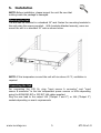
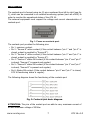
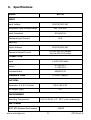
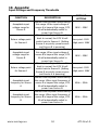
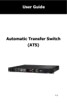
User Guide Automatic Transfer Switch (ATS 16) www.nextups.eu Table of Contents 1. Introduction ................................................................ 2 2. Product Overview ........................................................ 2 3. Important Safety Warnings ........................................... 3 4. Operation Indicators & Status ....................................... 3 5. Installation .................................................................. 5 6. Operation .................................................................... 6 7. Communication Port ..................................................... 6 8. Trouble Shooting ......................................................... 8 9. Specifications .............................................................. 9 10. Appendix: ................................................................. 10 www.nextups.eu 1 ATS 16 v1.0 1. Introduction This ATS 16 product is designed with two independent power inlets to supply power to the load from a primary power source. Should primary power source fail, the secondary will automatically back up the connected equipment without any interruption. The transfer time from one line to another is seamless to the connected equipment. After switching to a secondary power source, the ATS 16 can also switch power back to the primary input when power to the primary input is restored. Package contents: l ATS 16 module l User manual l mounting brackets 2. Product Overview Front View: (1) Power switch for input source A (2) Power switch for input source B (3) Circuit breaker for output 2 (4) Circuit breaker for output 3 (5) USB communication port (6) RS-232 communication port (7) Communication slot (8)Operation indicators (please refer to section 4 for the details) Back View (1) Contact port (please refer to section 7 for the details) (2) Output receptacles “Output 3” (IEC 10A) (3) Output receptacles “Output 2” (IEC 10A) (4) Output receptacle “Output 1” (IEC 16A) (5) Input source A connector (6) Input source B connector www.nextups.eu 2 ATS 16 v1.0 3. Important Safety Warnings Before using the unit, please read all instructions and cautionary markings on the unit, this manual and the batteries. WARNING!! The ATS 16 must be connected to earth when in use. In line with current regulations, only use the cables that have been supplied with the machine. The power supply socket must be easily accessible to the operator. WARNING!! The ATS 16 has been designed exclusively to operate indoors. It is advisable to install it in areas where no inflammable liquids or gases, or other harmful or noxious substances, have been stored. ATTENTION!! A soft damp cloth may be used to clean the outside of the machine (always with the system disconnected from the mains power supply and users). Do not use any type of solvent as this may damage the external finishing of the machine. ATTENTION!! The ATS 16 has been designed exclusively for professional use. NOTE: These instructions may be modified by the wiring regulations in force in the country where the ATS 16 is purchased. 4. Operation Indicators & Status (1) Source preference selector (2) Priority setting LEDs (3) Power source status LEDs (4) Output source LEDs (5) Fault indicator (6) Alarm mute button www.nextups.eu 3 ATS 16 v1.0 Indication LED type description Priority setting LEDs LED status Source A (2) ON Source B (2) OFF Source A (2) OFF Source B (2) ON Status of source A (3) Power source status Status of source B (3) Output status Alarm Output from source A (4) Output from source B (4) Output from source A (4) Output from source B (4) Output from source A (4) Output from source B (4) Fault (5) Condition Source A is priority Source B is priority OFF Inlet A has no power input ON Inlet A has power input, and power is OK Flashing Inlet A has power input, but power is out of SPEC OFF Inlet B has no power input ON Inlet B has power, and power is OK Flashing Inlet B has power input, but power is out of SPEC ON Alarm OFF OFF OFF OFF OFF OFF OFF OFF Power A is output OFF OFF OFF Power B is output OFF ON OFF NO OUTPUT OFF OFF OFF Alarm not present OFF ON Alarm present Continuously www.nextups.eu 4 ATS 16 v1.0 5. Installation NOTE: Before installation, please inspect the unit. Be sure that nothing inside the package is damaged. Mounting the Unit The unit can be mounted in a standard 19" rack. Fasten the mounting brackets to the unit using the screws provided. With brackets attached securely, users can mount the unit in a standard 19" rack as shown below. NOTE: If the temperature around the unit will rise above 40 °C, ventilation is required Connecting the Unit For connecting the ATS 16, plug “input source A connector” and “input source B connector” to the two independent power sources or UPSs depending using the SCHUCKO-IEC or IEC-IEC 16A cables supplied. Plug the user load to the output 10A (“Output 1 and 2”) or 16A (“Output 3”) sockets depending on user’s requirements. www.nextups.eu 5 ATS 16 v1.0 6. Operation Power On/Off Put the input power switch in “ON” position. The output will then be supplied by the source set as selected. Setting priority of power source It is possible to set the power source preference to supply the output by pushing the button of “source preference selector”. The default power source is “Source A”. Function Source perference selector 7. Description Selection of input that normally supplies the load Possible configuration • Source A • Source B Default Source A Communication Port The ATS 16 is supplied with the following communication ports: l Serial port is available with RS232 com. port and USB com. port on the front panel. NOTE: the use of one port automatically excludes the other. l Contacts port on the rear panel. Serial Ports: RS-232 & USB connectors RS-232 connector PIN # 1 NAME USB connector TYPE SIGNAL 2 TX OUT Serial line TX 3 RX IN Serial line RX 4 5 GND POWER 6 +12V POWER 7 8 PIN # SIGNAL 1 VBUS 2 D- 3 D+ 4 GND 9 NOTE: The utilization of the communication port is optional and it is not necessary for the correct functioning of the ATS 16. www.nextups.eu 6 ATS 16 v1.0 Contact Ports The contacts port is formed using six (6) pins numbered from left to right (see fig. 1), which can be connected to an external monitoring system (such as a BMS) in order to monitor the operational status of the ATS 16. The external equipment must respect the voltage and current characteristics of contacts port. Fig. 1: Focus on contacts port. The contacts port provides the following pins: • Pin 1: common contact. • Pin 2: “Source B” active contact (if the contact between “pin 1” and “pin 2” is closed, output is supplied by “Source B”). • Pin 3: “Source A” active contact (if the contact between “pin 3” and “pin 1” is closed, output is supplied by “Source A”). • Pin 4: “Source A” status OK contact (if the contact between “pin 4” and “pin 1” is closed, “Source A” is present and regular). • Pin 5: “Source B” status OK contact (if the contact between “pin 5” and “pin 1” is closed, “Source B” is present and regular). • Pin 6: Status OK contact (if the contact between “pin 6” and “pin 1” is closed, ATS 16 functioning status is regular). The following diagram shows the functioning of the contacts port. Fig. 2: Contacts port basic diagram. ATTENTION: The pins of the contact port are able to carry maximum current of 8A and maximum voltage of 250Vac. www.nextups.eu 7 ATS 16 v1.0 8. Trouble Shooting Use the table below to solve minor problems. Problem The ATS 16 with the mains voltage present, does don’t turn on. (The LEDs does not flash and no alarm sounds.) Possible Cause Solution No connection with input plugs Connect the mains to the input plugs as indicated in the installation section. Input switch in “OFF” position Turn the input switches in “ON” position. Check that the mains voltage is present or check if the UPS supplying the ATS 16 is powered on. Reset the protective device. Warning: check that there is no overload or short-circuit at the output of the UPS. Input power failure Protective device upstream activated No connection with Connect the load to the output sockets output sockets The load is not powered. The display shows nothing or provides incorrect information. The display is off but the load is powered. The thermal protection device will operate in the event of a short circuit or overload on one of the 10A output sockets. The thermal protection can be reset by pushing the button in which will result in the power being reconnected to the load. Therefore prior to attempting a reset of the thermal protection, please check the connected loads rating and/or determine if there are any problems. Then once reset, reconnect each load one at a time to ensure no problems exists. Shut down the ATS 16 completely and wait for a few seconds. Switch the ATS 16 on again, if the problem persists, contact the nearest technical support centre. Intervention of 10A thermal protection There is power supply problem in display. There is power supply problem in display. Contact the nearest N E X T U P S S y s t e m s technical support centre. If there is any abnormal situations occur, which doesn't list above, please call the NEXT UPS Systems service people immediately for professional examine. www.nextups.eu 8 ATS 16 v1.0 9. Specifications MODEL ATS 16 INPUT Input Voltage Acceptable Input Voltage Range Input Frequency Maximum Input Current 220/230/240 VAC 180 - 258 VAC 50 Hz/60 Hz 16 A OUTPUT Output Voltage 220/230/240 VAC 10 A for IEC-C13 outlets 16 A for IEC-C19 outlet Maximum Output Current CONNECTION Input 2 x IEC-C20 inlets 8 x IEC-C13 1 x IEC-C19 Output Communication TRANSFER TIME USB/RS-232 9-12ms (Typical) PHYSICAL Dimension, D X W X H (mm) Net Weight (kgs) 330 X 483 X 44 5.0 ENVIRONMENT Operating Temperature 0-95 % RH @ -5°C- 45°C (non-condensing) NEXT Partnr NEXT UPS Systems Part number www.nextups.eu 9 88009 ATS 16 v1.0 10. Appendix: Input Voltage and Frequency Thresholds FUNCTION Acceptable input voltage range for Source A Return voltage point for Source A Acceptable input voltage range for Source B Return voltage point for Source A Acceptable input frequency for Source A Acceptable input frequency for Source B DEFAULT SETTING DESCRIPTION Source A will be power source during this range. When input voltage of source A is beyond this range, ATS 16 will automatically switch to power from Source B. When input voltage of Source A is back to normal, the ATS 16 will switch back to Source A. (Setting Source A as priority power source and Source B is powering) Source B will be power source during this range. When input voltage of source B is beyond this range, ATS 16 will automatically switch to power from Source A. When input voltage of Source B is back to normal, the ATS 16 will switch back to Source B. (Setting Source B as priority power source and Source A is powering) Source A will be power source during this range. When input frequency of source A is beyond this range, ATS 16 will automatically switch to power from Source B. Source B will be power source during this range. When input frequency of source B is beyond this range, ATS 16 will automatically switch to power from Source A. 180V – 258V Low point: 190V High point: 248V 180V – 258V Low point: 190V High point: 248V 45Hz – 55Hz 45Hz – 55Hz www.nextups.eu 10 ATS 16 v1.0