1
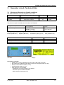
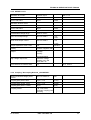
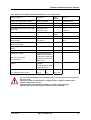
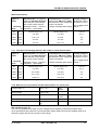
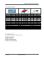
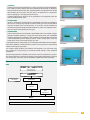
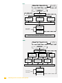
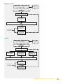
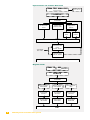
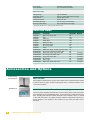
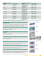
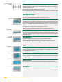
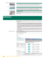
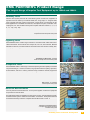
EMC TESTS, SEMINARS, HARD AND SOFTWARE
Technical Specification
No. TRA2000.doc
Revised 04.January 2007
1
Tester Type
TRA2000-System with S/N > 800
The TRA2000 includes all circuits and CDN to carry out immunity tests on power supply in accordance
with IEC 61000-4-4 Ed.2, -5 Ed.2, -11 Ed.2. When accessories are added the TRA2000 can be
expanded to comply with IEC 61000-4-2, -8, -9, -12 Ed.2 (ring wave), -16, -29. The Genes software to
the TRA2000 is the most sophisticated software for Transient Immunity tests.
1
Tester Type TRA2000-System
1.1
Introduction
1
1
2
General
2.1
Brief description of the generator
2.2
EUT connection (equipment under test)
2.3
Standards, applications
2
2
2
2
3
Generator circuit, Technical Data
3.1
Mechanical dimensions, climatic conditions
3.2
Technical data
3.2.1
EFT circuit
3.2.2
Coupling / De-coupling Network EFT
3.2.3
ESD circuit, accessories ESD Mouse
3.2.4
SURGE circuit
3.2.5
Coupling / De-coupling Network „CDN-SURGE“
3.2.6
DIPS circuit complies with IEC 61000-4-11 for a.c. power ports.
3.2.7
Interruption and Voltage Variation IEC 61000-4-11 with external Variac
3.2.8
DIPS circuit in accordance with IEC 61000-4-29 for d.c. power ports.
3.2.9
Overview accessories
3.2.10
Overview versions
3
3
4
4
4
5
6
6
7
8
8
9
9
1.1 Introduction
The one box solution for full compliance transient immunity testing. The TRANSIENT2000 is a flexible
one box test and measurement equipment for immunity transient tests on power supply 110V or 230V.
The TRA2000 generators are compact and have an excellent value for money.
• All relevant parameters in one display
• Easy paramet4er changes during operation
• Magnetic field up to full levels
• Protocol when needed
• The GENECS Software is the most sophisticated Software for transient immunity tests
• Dialogue line language can be chosen
04.01.2007
E M C P AR T N E R AG
1/
TECHNICAL SPECIFICATION E-TRA2000
2
General
2.1 Brief description of the generator
The TRA2000 includes all necessary circuit ESD, EFT, SURGE, Dips, Variation -immunity tests. In
addition outstanding feature are:
• Easy protocol of all test results
• Automatic summarisation of the test results in the log file
• Measurements of i and v peak for SURGE.
• Variac in the standard unit for voltage variation, magnetic field tests and d.c. and a.c. test in
accordance with IEC 61000-4-16
2.2 EUT connection (equipment under test)
The EUT is connected on the front panel of the TRA2000 tester.
2.3 Standards, applications
Basic Standard
IEC/EN
EMC PARTNER Generators
Remarks
Generic Standards
application IEC/EN
61000-4-2
TRANSIENT2000 (ESD) plus ESDMouse
Full compliant
61000-6-1
61000-4-4 Ed.2
TRANSIENT2000 (EFT)
Full compliant
61000-6-1
61000-4-5 Ed.2
TRANSIENT2000 (SURGE) CWG
Full compliant
61000-6-1
61000-4-11
Ed.2
TRANSIENT2000 (DIPS)
Full compliant
61000-6-1
61000-4-29
TRANSIENT-1000 (DIPS on dc)
DIPS Full compliant no variation
On request:
TRA2000 can carry out following tests in accordance with listed standards, with relevant TRA2000Inx
model
61000-4-5
TRANSIENT2000INx
Full compliant
61000-6-1
61000-4-8
TRANSIENT2000 (Variation) plus
MF1000-1; -2;-3, MF1STAND
Full compliant
61000-6-1
61000-4-9
TRANSIENT2000 (SURGE) & MF1000-1 Full compliant
61000-6-1
61000-4-12
Ed.2
TRANSIENT2000INx
Full compliant
61000-6-1
TRANSIENT2000 part DC and 50/60Hz
No CW signal generator included up to
150 kHz
10/700
"Ring wave"
61000-4-16
04.01.2007
E M C P AR T N E R AG
2/9
TECHNICAL SPECIFICATION E-TRA2000
3
Generator circuit, Technical Data
3.1 Mechanical dimensions, climatic conditions
The Tester TRA2000 is a 19“ plug-in system for a 19“ rack.
Type
TRA2000
Dimension [ mm ]
Weight
width x depth x height [ mm ]
[ kg ]
520 x 433 x 180 mm
32
Version
19“ 4UH
The power line input is located at the rear side of the TRA2000.
Voltage between phase and neutral
Power consumption
230 V ( 50 Hz )
115 V ( 60 Hz )
operation mode< 800 VA
Standby < 100 VA
Power OFF < 10 VA
Following power cords can be ordered:
Europe ( CEE-7/VII )
England ( BS-1363 )
Switzerland ( SEV Type 12 )
Environment conditions
Temperature range
Humidity
Pressure
°C
rh %
kPa
TRA2000“
Display
± 10 %
± 10 %
( 230 V, 50 Hz )
( 115 V, 60 Hz )
USA ( NEMA5-15P )
0 to 35 °C
25 to 80%
86 to 106
Accessories included:
• Power cord (1 x 2m): D Schuko (16A), CH (10A), USA (16A), UK (13A)
• MC cables with protected banana plugs; black, blue and green/yellow (3 x 2m)
• Remote control cable 25/9 pole (1 x 3m)
• CENTRONICS adapter (1 pce)
• User manual (1 pce) including:
- Declarations of conformity: EMC, LVD, BASIC
- Verification protocol EMC PARTNER
- EMCP Software Package (1CD)
04.01.2007
E M C P AR T N E R AG
3/9
TECHNICAL SPECIFICATION E-TRA2000
3.2 Technical data
3.2.1 EFT circuit
Voltage waveform into 50 Ω:
Impulse Outpur
Chap 14.1.1 IEC 61000-4-4
Risetime
5 ns
± 30%
Half time value
50 ns
± 30%
Risetime
5 ns
± 30%
Half time value
100 ns
- 50 ns
Adjustable voltage range
250 V to 4400 V
Voltage amplitude into 50 Ω
125 V to 2000 V
± 10%
Voltage amplitude into 1000 Ω
250 V to 4000 V
± 20%
Source impedance
50 Ω
± 10%
Spike frequency
1 kHz up to 1 MHz
Maximum Spikes per seconds
8’000 at 1000 V
Burst duration
0,001 ms up to 20 ms
Burst repetition
1 ms up to 1000 ms
Polarity
positive / negative
Ramps
-Voltage
Voltage waveform into 1000 Ω:
+ 100 ns
1000 at 4000 V
-Spike frequency
-Synchronisation
-Burst duration
High voltage output
10 nF decoupled
max.
450 V ac
3.2.2 Coupling / De-coupling Network EFT
Maximum EUT power supply voltage 260 V ac 50/60 Hz
Maximum allowed continuous current 16 A
Spike waveform superimposed onto
the lines of the EUT power supply
within the tolerances as
above
Chap 14.1.1 IEC 61000-4-4
damping between output and input of better 30 dB
the CDN
Coupling paths:
04.01.2007
L-GND; N-GND, PEGND, L+N+PE - GND
L+N - GND; L+PE GND; N+PE - GND
E M C P AR T N E R AG
4/9
TECHNICAL SPECIFICATION E-TRA2000
3.2.3 ESD circuit, accessories ESD Mouse
Energy storage capacitance
150 pF
± 10%
Discharge resistance
330 Ω
± 10%
Charging resistance
54 MΩ
holding time (drop to 95%)
better than 5 s
Current rise time, 2 Ω load
0,7 to 1 ns
See 14.1.2
IEC 61000-4-2
Definition of current waveform:
Current amplitude at 30 ns
4 to 16 A
± 30%
Current amplitude at 60 ns
2 to 8 A
± 30%
Voltage range „air discharge“
2 to 15 kV
± 10%
Voltage range „contact discharge“
2 to 8 kV
± 10%
First current amplitude into 2 Ω
„contact discharge“
7,5 to 30 A
± 10%
Polarity
positive / negative;
automatic switchover
Number of discharges
-preselectable
Detection of the number of
discharges
-count every pulse
Ramps
voltage amplitude
changes from shot to
shot, alternate polarity
Reporting
test sequence with the
number of discharges
-count discharge only.
Only the impulses
whereas the voltage of
the discharge capacitor
tropes lower then 10%
of the charging voltage
are counted.
-Voltage amplitude
-Polarity
Discharge modes:
-Air discharge
-Contact discharge
Repetition of the discharges
1 to 20 Hz
Single discharge
04.01.2007
E M C P AR T N E R AG
5/9
TECHNICAL SPECIFICATION E-TRA2000
3.2.4 SURGE circuit
Waveform at no load :
Impulse output
See 14.1.3
Front time
1.2 μs
± 30%
Time to half value
50 μs
± 20%
Front time
8 μs
± 20%
Time to half value
20 μs
± 20%
Preselectable voltage range
220V to 4100 V
Open circuit output range
250 V to 4000 V
- 0%;
+10%
Short circuit output current
125 A to 2000 A
- 0%
Waveform at short circuit:
-
+ 10%
Output impedance Umax / Imax
2Ω
Polarity
positive / negative / altn
Ramps
-Voltage
± 0.25 Ω
-Polarity
-Synchronisation
High voltage output "low"
maximum voltage
between „low“ and
earth 260 V ac
Time between successive shots
3s
5s at 4000 V
3.2.5 Coupling / De-coupling Network „CDN-SURGE“
Maximum allowed voltage phase
neutral
260 V ac 50/60 Hz
16A
Coupling path phase- earth
9 μF + 10 Ω
(L-PE)
Coupling path neutral - earth
9 μF + 10 Ω
(N-PE)
Coupling path phase - neutral
18 μF
(L-N)
Coupling modes:
L-N; L-PE; N-PE,
automatic coupling path
switching
04.01.2007
E M C P AR T N E R AG
6/9
TECHNICAL SPECIFICATION E-TRA2000
3.2.6 DIPS circuit complies with IEC 61000-4-11 for a.c. power ports.
Voltage range a.c.
0 to 260 V
EUT
Power
See 4.2
Frequency range without variac
DC up to 400 Hz
external Source
Frequency range with variac involved 48 Hz to 400 Hz
external Source
Nominal current
16A
Interruption with internal variac and
linear load
maximum 12 A
< 5s
maximum 16 A
< 300 ms
Inrush current
500 A Peak
Interruption time
50 μs to 30 s
phase angle selectable
Amplitude interruptions with the
internal variac
continuously selectable Max. 5A
0 to 100 %
IEC: 0 %, 40 %, 70 %,
80%
Phase angle for turn ON and OFF of
the EUT selectable
0 to 360°
± 5°
Voltage variation with the internal
variac
0 to 110 %
Max. 5A
2 s to 30000 s
Voltage variation with external variac 0 to 110 %
Max 16A
2 s to 30000 s
- 0%,
+30%
Less than 1 period
Interruption within one
period. Input as angle
More than one period
Interruption longer then
one period. Input in ms
d.c. interruption
Ramps
See 14.1.4
Input in ms
-Voltage
-Synchronisation angle
-Interruption time
Interruption for all kind of loads
DIP
% UT
UT= voltage at EUT Power 1
100 %
0%
0 to 16 A
For 0 to 100% interruptions the internal Variac is not used, the test can be carried
out up to 16 A.
Interruption with UT =EUT Power 1 voltage not zero, using the internal variac
limits the EUT power current.
The maximum current values are listed in the table on the next page.
Different load types influence the maximum current capability.
04.01.2007
E M C P AR T N E R AG
7/9
TECHNICAL SPECIFICATION E-TRA2000
With internal Variac:
Variable power consumption
maximum 2.6 kW at UT 230 V.
With reduction of the voltage
the current is also reduced.
Types of
loads:
switching
Constant power consumption
maximum 1,2 kW at UT = 220V.
With reduction of the voltage the
current is increased.
Examples: Ohmic -, inductive -, Example: switched power supply
capacitive -, mixed loads
voltage change in
% of UT at current
change 0 to 100 %
UT= voltage at EUT
Power 1
from
to
UT
% UT
current range r.m.s
current range r.m.s
% of UT
100 %
0%
0 to 16A
0 to 16A
0.7 %
100%
80%
0 to 10 A
0 to 5A
4%
100%
70%
0 to 9 A
0 to 6 A
4%
0 to 10 A
5%
100% 40%
0 to 5 A
Note: all values apply for switching time at %UT< 5 s
3.2.7 Interruption and Voltage Variation IEC 61000-4-11 with external Variac
Variable power consumption
maximum 3.7 kW at UT 230 V.
With reduction of the voltage
the current is also reduced.
Types of
loads:
switching
Constant power consumption
maximum 3,7 kW at UT = 220V.
With reduction of the voltage the
current is increased.
Examples: Ohmic -, inductive -, Example: switched power supply
capacitive -, mixed loads
voltage change in
% of UT at current
change 0 to 100 %
UT= voltage at EUT
Power 1
from
to
UT
% UT
current range r.m.s
current range r.m.s
% of UT
100 %
0%
0 to 16A
0 to 16A
0.7 %
100%
80%
0 to 12.8 A
0 to 20A
4%
100%
70%
0 to 11.2 A
0 to 23 A
4%
0 to 40 A
5%
100% 40%
0 to 6.5 A
Note: all values apply for switching time at %UT< 5 s
3.2.8 DIPS circuit in accordance with IEC 61000-4-29 for d.c. power ports.
Voltage range d.c.
20 to 110 V
Current range
0 up to 16A
Inrush current capability at 110 V
220A Peak
Interruption time
1ms up to 29999 ms
Rise and fall time at 100 Ohm load
between 1 μs and 50
μs
EUT
Power
- 0%,
+30%
See 6.1.1
See 6.1
IEC 61000-4-29 page 19:
The use of a generator with higher or lower voltage/current capability is allowed provided that the
other specifications are preserved. The test generator steady state power/current capability shall be at
least 20% greater than the EUT power/current ratings.
04.01.2007
E M C P AR T N E R AG
8/9
TECHNICAL SPECIFICATION E-TRA2000
3.2.9 Overview accessories
Test System And Standards
Enclosure
Ports
EUT ports
Verification, PC-Control- Accessories
Signal, Data,
I/O Lines Ports
EUT
EUT
Equipment
Under Test
AC / DC
Power Ports
Earth Port
IEC Standards
Max. Values of EMCPARTNER Testers
Tester type
AC/DC
1000-4-2 ESD
1000-4-4 EFT
1000-4-5 SURGE
1000-4-8 a.c. MF
1000-4-9 Surge MF
1000-4-10 Oscil. MF
1000-4-11 DIPS
1000-4-11 Variation
1000-4-12 Ring
1000-4-12 Oscillation
CD* 8kV; AD* 15kV
1600 A/m
TRA-2000
TRA-2000
TRA-2000
TRA-2000
TRA-2000
120 A/m
MIGOS-OM
1 (12)
1 (12)
1 (6, 12)
1000-4-13 Harmonics
1000-4-14 V-variation
1000-4-16 Common Mode
16 A, 230 V
1000-4-17 Ripple on d.c.
1000-4-29 DIP on d.c.
16 A, 200V d.c.
4,4 kV; 1MHz
CWG 4,1 kV 2 kA
160A/m, 1050A/m
16 A different levels
5 A different levels
6 kV
3 kV, 1MHz, 100kHz
16 A, 230 V
300 V a.c., 300 V d.c.
16 A , 110V
N°
1
Description / Accessories
See colon "Tester type"
2
3
Signal
Telecom
1+3
1+18
-
Signal
Earth
Enclosure
1+3
1+4
-
1+3
1+5
-
In addition we offer for carrying out EMC test
and measurements in your company:
Test set-up
Control via PC
20 (21)
20 (21)
22
22
22
-
14 (16, 23)
14 (16, 23)
14 (16, 23)
14 (16, 23)
14 (16, 23)
-
1+2 (13)
1+5
1+7+8+15 (22)
1+7+8 (22)
1+7+8 (22)
-
Calibration
Verification
9,19
10,19
19
11,19
TRA-2000
TRA-2000
MIG0603IN4
MIGOS-OSI
14 (16, 23)
1 (12, 24)
1 (24)
-
-
-
-
19
-
14 (16, 23)
HAR-1000
HAR-1000
TRA-2000
1
1 (6, 12)
-
1+17
1+17
-
-
19
19
19
-
14 (16)
14 (16)
14 (16, 23)
HAR-1000
TRA-2000
1 (6, 12)
1
-
-
-
-
19
19
-
14 (16)
14 (16, 23)
N°
9
Description / Accessories
Measuring Target ESD 2 Ω
N°
17
Description / Accessories
NW16S, CN16, CN16T
ESD discharge circuit, Relay, Finger
10
Coupling Kit Telecom CDNKIT1000T
11
Measuring set EFT 50 Ω / 1 kΩ
Measuring-set DIPS (inrush current)
18
Coupling clamp CNEFT1000
19
Certificate and Protocol
4
SURGE coupling kit CDNKIT1000
12
Three phase coupling CDN2000-06-32
20
Connection set
5
Test tip CN-TRA
13
ESD stand
21
Test set-up accessories
6
External Variac VAREXT-1000 (16/32A)
14
GENECS to TRA, HARCS-Immunity to HAR
22
Stand to MF1000-1 or MF1000-2
7
Antenna for magnetic field MF1000-1 1x1m
15
Antenna for magnetic field MF1000-1 1x1m, 3s
23
Fibre Optic link
8
Antenna for magnetic field MF1000-2 1x2.6m
16
EUT Monitor for EUT failed control
24
Three phase coupling CDN2000-06-25
*CD = Contact Discharge *AD = Air Discharge
3.2.10 Overview versions
The TRA2000 can be ordered in different versions as:
TRA2000 Version EFT-ESD
TRA2000 Version SURGE
TRA2000 Version DIPS
TRA2000 Version DIPS-SURGE
TRA2000 Version EFT-ESD-DIPS
TRA2000 Version EFT-ESD-SURGE
04.01.2007
E M C P AR T N E R AG
9/9
Immunity Tests
Transient
Test System
Brief Overview of Phenomena. . . . . . . . . . . . . . . . 2
Applicable Standards . . . . . . . . . . . . . . . . . . . 3
Test System Overview. . . . . . . . . . . . . . . . . . . 4
Generator Specifications. . . . . . . . . . . . . . . . . . 9
Accessories and Options. . . . . . . . . . . . . . . . . 10
Software . . . . . . . . . . . . . . . . . . . . . . . 14
EMC PARTNER’s Product Range . . . . . . . . . . . . . . 15
Immunity Tests: Transient Test System
1
Brief Overview of Phenomena
Transient Test System generates EMC events that can be observed in the low power
distribution system, telecommunication or data lines.
Transient Test System replicates the following phenomena:
- Electrostatic Discharges (ESD)
A person becomes electrostatically charged by walking over an insulating floor surface. The capacity of the body can be charged to several kilovolts and is discharged
when contact is made with an electronic unit or system. The discharge is visible as a
spark in many cases and can be felt by the person concerned, who receives a „shock“.
The discharges are harmless to humans, but not to sensitive, electronic equipment.
The resulting currents cause interference or make entire systems „crash“.
- Electric Fast Transients (EFT) / Burst
Industrial measurement and control equipment nearly always use conventional
control units containing relays or other electro-mechanical switching devices. Fluorescent lamp ballast units, insufficiently suppressed motors (hair dryers, vacuum
cleaners, drills, etc.) are found everywhere in the public power supply. All of these are
primarily inductive loads which generate interference when switched on or off. EFT
events, can cause microprocessor units to malfunction or reset, with corresponding
disruption to normal operation.
- Combination Wave Generator (CWG), Ring Wave and 10/700µs
Surge events can be generated by lightning phenomena, switching transients or the
activation of protection devices in the power distribution system. A surge itself is
influenced by the propagation path taken so that impulses from the same event may
have different forms depending upon where a measurement is taken. Combination
Wave Generators (CWG) simulate a surge event in power lines close to or within
buildings. Ring waves are bipolar oscillatory events, only measured on power lines
within a well protected environment. Because of the special impedance characteristics within telephone systems, surges tend to be longer and are represented by
the 10/700µs waveform.
Mostly the disturbances are tolerable because they are single events.
- Power Frequency and Pulse Magnetic Fields
Under normal operating conditions, an AC current generates a steady magnetic
field so that equipment, such as monitors, close to AC power lines could suffer interference. Under fault conditions, a sudden high current level can result in a short
duration magnetic field.
Lightning strokes or short circuit fault currents in the power network can generate
high level short duration magnetic fields.
- AC & DC Dips/Interrupts
Voltage failures occur following switching operations, short-circuits, response of
fuses and when running up heavy loads.
The quality of the electrical power supply is increasingly becoming a central topic
of discussion. The interference sources in the mains, caused by electronic power
control with non-linear components e.g. thyristors are used more frequently in domestic appliances such as hotplates, heating units, washing machines, television
sets, economy lamps, PCs and industrial systems with speed-controlled drives.
Accessories are available to extend applications to include:
- Common mode tests (DC to 150kHz)
- Telecommunication tests (10/700µs balanced & un-balanced)
- Three phase testing to 32A (EFT, surge, ring wave)
- Three phase testing to 32A (dips & interrupts)
2
Immunity Tests: Transient Test System
Applicable Standards
International Electrotechnical Committee (IEC)
IEC 61000-4-2 (Ed1.2:2001): Testing and measurement techniques - Electrostatic
discharge immunity test.
IEC 61000-4-4 (Ed2:2004): Testing and measurement techniques - Electrical fast
transient / burst immunity test.
IEC 61000-4-5 (Ed2:2005): Testing and measurement techniques - Surge immunity
test.
IEC 61000-4-8 (Ed1.1:2001): Testing and measurement techniques - Power frequency
magnetic field immunity test.
IEC 61000-4-9 (Ed1.1:2001): Testing and measurement techniques - Pulse magnetic
field immunity test.
IEC 61000-4-11 (Ed2:2004): Testing and measurement techniques - Voltage dips, short
interruptions and voltage variations immunity tests.
IEC 61000-4-12 (Ed2:2006): Testing and measurement techniques - Oscillatory waves
immunity test (Ring wave).
IEC 61000-4-16p (Ed1.1:2002): Testing and measurement techniques - Test for immunity
to conducted, common mode disturbances in the frequency range 0Hz to 150kHz.
IEC 61000-4-29 (Ed1:2000): Testing and measurement techniques - Voltage dips, short
interruptions and voltage variations on d.c. input power port immunity tests.
European Standard (EN)
The same standards are applicable as for IEC (see above).
International Telecommunications Union (ITU)
K.20 (February 2000): Resistibility of Telecommunications Equipment installed in a
telecommunications centre to overvoltages and overcurrents
American National Standards Institute (ANSI)
C62.41 (Date): American National Standard for Electrostatic Discharge Test Methodologies and Criteria for Electronic Equipment.
Immunity Tests: Transient Test System
3
Test System Overview
Test System Feature
Transient Test System has many unique and outstanding features:
- Up to 6kV surge levels
- CWG, 10/700µs and ring wave together in one instrument
- Internal motor variac
- All parameters on one screen
- Parameter change during operation (+/-)
- Internal program memory
- Backlit LCD display
- Electronic polarity change
- Semiconductor switches
- Compact design
- Fulfills ALL standard requirements
- Magnetic field test menu
- Expansion to 3-phase capability
- Remote control and software upgrade through standard interface
- Wide range of accessories
- 2 year warranty
User Benefits
The technical excellence and many unique features translate directly into benefits for
the user:
- Cost effective solution to meet many test requirements
- Increase quality of test object
- Real time parameter change, ideal development tool
- Save operator time with the automated test routines and test report facility
- Easy integration into a full test suite
- Unparalleled reliability and system up-time
Generators
Transient Test System comprises three generator models (TRA2000, TRA2000IN4
and TRA2000IN6).
Available with single or multiple events (ESD, EFT, surge, ring, dips), they can be upgraded to add further capability when required. Unique in their class, all three models
include, as standard, an internal motor variac to enable dips and variation tests, at any
user programmable level, as per IEC 61000-4-11.
The most significant test parameters can be programmed and then adjusted in real
time to assist in finding the exact immunity level of an EUT. The +/- keys are used to
adjust; test voltage level, EFT spike frequency, EFT burst duration, synchronisation
angle, polarity and EUT supply voltage (via internal variac). The coupling paths; Line,
Neutral and Protective Earth can either be automatically programmed or manually
selected using switches on the front panel.
Standard accessories include 10A and 16A mains cables, GENECS remote control
software on a CD, serial link cable to use with the GENECS software, user manual
with verification protocol and conformity declaration.
4
Immunity Tests: Transient Test System
- TRA2000
Capable of being equipped with ESD up to 15kV air discharge (requires ESD2000),
EFT, CWG up to 4kV (1.2/50µs open circuit and 8/20µs short circuit), AC dips/interrupts & variations plus DC interrupts. TRA2000 features a single phase 16A AC/DC
CDN enabling all power borne immunity tests to be performed on a single EUT
without unplugging or reconfiguring the test set-up.
TRA2000 limited feature versions can be upgraded to full configuration when the
need for additional tests arises.
- TRA2000IN4
Similar to TRA2000 as described above, TRA2000IN4 has enhanced capability in
the form of a 10/700µs surge impulse for telecom testing up to 4kV and the 100kHz
ring wave for ANSI C62.41 and IEC61000-4-12, up to 6kV. Just like TRA2000, an
automatic integrated single phase CDN enables EUT power to be supplied continuosly even when switching between test types.
TRA2000
- TRA2000IN6
A further enhancement of the TRA2000, TRA2000IN6 is the most complete compact
generator available. Offering in a single unit phenomenal power and unparalleled
capability. All the features available in both TRA2000 and TRA2000IN4 are included
in the TRA2000IN6, plus the ability to perform CWG 1.2/50µs open circuit and
8/20µs short circuit and 10/700µs surges up to 6kV.
Long duration testing is made easier by use of the EMC PARTNER software packages.
Using either GENECS or TEMA software, the units can be programmed, automatically
started and test reports generated.
TRA2000IN4
The compact design enables many different test standards to be performed using
only a single unit. A broad range of accessories enable testing to many additional
applications.
NW May 15. 2008
Z:\VK\Verkaufsinstrumente\Brochures\Immunity\Transient\TRA-ESD.flo
Special configurations are available to meet unique customer requirements, long duration voltage interrupts as required for ESD
Electricity meter testing (IEC62052-11 Annex B)
are one example of the many unique capabilities available from EMC PARTNER.
Flowcharts
ESD
TRA2000IN6
TEMA TEST MANAGER
customized solution
GENECS
ESD Test Cables
TRA Set-up
TRA2000, TRA2000IN4 &
TRA2000IN6
150pF / 330 ohm
ESD2000
Vertical Coupling
Plate
ESD-VCP50
EUT
Calibration Devices (ESD-Target1, ESD-Target2)
Immunity Tests: Transient Test System
5
EFT
TEMA TEST MANAGER
DSO Option
control TEK DSO
customized solution
GENECS
EFT Test Cables
TRA Set-up
TRA2000, TRA2000IN4 &
TRA2000IN6
Single Phase
AC / DC Power
Direct
Differential Output
Adpater CN-BALUN
Data Lines
CN-EFT1000
EUT
Three Phase
AC / DC Power
CDN2000-06-32
Three Phase
EUT Power
Three Phase
AC / DC Power
CDN2000A-06-32
Z:\VK\Verkaufsinstrumente\Brochures\Immunity\Transient\TRA-CWG.flo
NW May 15. 2008
Calibration Devices (VERI50-EFT, VERI1K-EFT, Adapter EFT-CDN)
CWG
CWG
TEMA TEST MANAGER
DSO Option
control TEK DSO
customized solution
GENECS
TRA2000, TRA2000IN4 &
TRA2000IN6
Railway Application
Option
NW-TRA-RAIL
Single Phase
AC / DC Power
Direct
Balanced
Telecom Lines
CDN-UTP
Coupling
Decoupling Modules
DN & CN2000-22-5
EUT
Three Phase
AC / DC Power
CDN2000-06-32
Three Phase
EUT Power
6
Immunity Tests: Transient Test System
Three Phase
AC / DC Power
CDN2000A-06-32
Un-balanced
Lines
CDN-KIT1000
Direct Injection
Probe
CN2000TT
Ring Wave 100kHz
TEMA TEST MANAGER
customized solution
DSO Option
control TEK DSO
GENECS
TRA2000IN4 & TRA2000IN6
Single Phase
AC / DC Power
Direct
EUT
Three Phase
AC / DC Power
CDN2000-06-32
Three Phase
Z:\VK\Verkaufsinstrumente\Brochures\Immunity\Transient\TRA-10-700.flo
EUT Power
NW May 15. 2008
Three Phase
AC / DC Power
CDN2000A-06-32
10/700us
10/700µs
TEMA TEST MANAGER
customized solution
DSO Option
control TEK DSO
GENECS
TRA2000IN4 & TRA2000IN6
25 ohm coupling
CN10-700E25
Balanced
Telecom Lines
CDN-UTP
Un-balanced
Telecom Lines
CDN-KIT1000
EUT
Three Phase
AC / DC Power
CDN2000-06-32
Three Phase
EUT Power
Three Phase
AC / DC Power
CDN2000A-06-32
Immunity Tests: Transient Test System
7
Z:\VK\Verkaufsinstrumente\Brochures\Immunity\Transient\TRA-DIPS.flo
NW May 15. 2008
DIPSand
/ VARIATIONS
& COMMON
MODE TESTS
Dips/Variations
Common Mode
Tests
TEMA TEST MANAGER
customized solution
DSO Option
control TEK DSO
GENECS
TRA2000, TRA2000IN4 &
TRA2000IN6
Single Phase
AC / DC Power
Direct
Variation 16A
VAR-EXT-1000
Common Mode
Testing Source
NW16S
Coupler
CN16
Coupler
CN16T
EUT
Three Phase
Interrupt AC / DC
Power
PFS32 / PFS63
Three Phase
EUT Power
Three Phase
DIPS AC Power
SRC32 / SRC63
Z:\VK\Verkaufsinstrumente\Brochures\Immunity\Transient\TRA-MAG.flo
NW May 15. 2008
Calibration Devices (DIPS100E, VERI-DIPS)
MAGNETIC FIELDS
Magnetic Fields
TEMA TEST MANAGER
customized solution
GENECS
TRA2000, TRA2000IN4 &
TRA2000IN6
Minimum Version
DIPS-SURGE
Minimum Version
DIPS-SURGE
Minimum Version
DIPS
1m x 1m Antenna
AC & Impulse
MF1000-1
1m x 2.6m Antenna
AC & Impulse
MF1000-2
1m x 1m Antenna
AC Short duration
MF1000-3
Support Stand
MF1STAND
Support Stand
MF1STAND
Support Stand
MF3STAND
EUT
8
Immunity Tests: Transient Test System
Generator Specifications
ESD
Air discharge
Contact discharge
Voltage increment resolution
Contact discharge repetition interval
Discharge detection
Discharge counter
Discharge polarity
Holding time
Programmable parameter ramps
Discharge trigger
2 up to 16kV
2 up to 10kV
1 volt steps
0.05 to 30s
every pulse or real discharges only
1 to 29999
positive, negative and alternating
5s
voltage, polarity
manual or automatic
EFT
Voltage range
Source impedance
Pulse front time at 50ohm
Pulse duration at 50ohm
Spike repetition frequency
Programmable parameter ramps
Spike distribution
0.25 up to 4.4kV
50ohm
5ns
50ns
up to 1MHz
voltage, spike frequency, burst duration,
synchronisation
IEC burst pattern and random
CWG
Voltage range
Current range
Source impedance
Pulse front time at open circuit
Pulse duration at open circuit
Pulse front time at short circuit
Pulse duration at short circuit
Pulse repetition
Programmable parameter ramps
Synchronisation on power line frequencies
0.25 up to 4.1kV (6kV for TRA2000IN6)
0.125 up to 2.1kA (3kA for TRA2000IN6)
2ohm
1.2µs
50µs
8µs
20µs
up to 20 pulses per minute
voltage, synchronisation
16Hz up to 400Hz
10/700µs
Voltage range
Current range
Source impedance
Pulse front time at open circuit
Pulse duration at open circuit
Pulse front time at short circuit
Pulse duration at short circuit
Pulse repetition
0.25 up to 4kV (6kV for TRA2000IN6)
16.6 up to 266A for TRA2000IN4 / 400A for
TRA2000IN6
15ohm + 25ohm
10µs
700µs
4µs (40ohm)
300µs (40ohm)
up to 4 pulses per minute
100kHz Ring Wave
Voltage range
Current range
Source impedance
Pulse front time at open circuit
Pulse oscillation frequency
0.25 up to 6kV
20 up to 500A
12ohm & 30ohm
0.5µs
100kHz
Immunity Tests: Transient Test System
9
Pulse decay
Pulse repetition
60% first to second peak
up to 10 pulses per minute
Dips/Interrupts
Voltage range
Frequency range
Rated current
Interruption period
Selectable dip range
Phase synchronisation
1)
0 up to 260Vrms
DC up to 400Hz with external supply
16A for dips 0/100%
50µs up to 30s
0 up to 100% continuously 1)
dips, interrupts & EUT supply
5A dips with standard variac. 16A dips requires VAR-EXT1000.
Selection Guide
Generator
TRA2000
TRA2000
TRA2000
TRA2000
TRA2000
TRA2000
TRA2000
TRA2000
TRA2000IN4
TRA2000IN4
TRA2000IN6
TRA2000IN6
TRA2000IN6
TRA2000IN6
TRA2000IN6
TRA2000IN6
Circuit(s)
ESD, EFT, surge, dips
dips
ESD, EFT
surge, dips
ESD, EFT, dips
ESD, EFT, surge
EFT, surge, dips
surge
ESD, EFT, surge, 10/700, ring wave, dips
EFT, surge, 10/700, ring wave, dips
ESD, EFT, surge, ring wave, dips
EFT, surge, ring wave, dips
surge, ring wave, dips
EFT, surge
ESD, surge
ESD, EFT, surge, ring wave
Upgrade
No
Yes
Yes
Yes
Yes
Yes
No
Yes
No
No
No
No
No
No
No
No
Option
10/700µs
10/700µs
10/700µs
10/700µs
10/700µs
10/700µs
Accessories and Options
Vertical Coupling
Plate ESD-VCP50
TEST SETUP
Test package for ESD and EFT testing. This includes all the mechanical items needed
to perform these test types. Vertical coupling plate with 2 x 470kohm resistors and 2
x 10cm EFT insulation.
CDN2000-06-32
CDN2000-06-32 for Three Phase Coupling
Add three phase capability with automatic or manual three phase coupling networks.
The CDN2000A-06-32 and CDN2000-06-32, can be used for EFT, CWG surge and ring
wave. Coupling path selection is either automatic under software control, or manual
on the CDN front panel. All coupling networks fulfill the requirements laid down in
the IEC 61000-4-4, IEC 61000-4-5, IEC 61000-4-12 (ring wave) and ANSI C62.41
standards.
10
Immunity Tests: Transient Test System
Single Phase Solutions
Generator
TRA2000
Internal CDN
280V L/N- PE
L to N 280V
TRA2000
280V L/N- PE
L to N 280V
TRA2000IN4
280V L/N- PE
L to N 280V
TRA2000IN4
280V L/N- PE
L to N 280V
TRA2000IN6
280V L/N- PE
L to N 280V
TRA2000IN6
280 V L/N- PE
L to N 280 V
TRA2000IN6
280V L/N- PE
L to N 280V
Three Phase Solutions
Coupler
CDN2000A-06-32 or
CDN2000-06-25 or
CDN2000-06-32
CDN2000A-06-32
Option 480V
External CDN
280V Lx/N to PE
415V Lx - LX/N
280V Lx/N to PE
480V Lx - LX/N
CDN2000A-06-32 or
CDN2000-06-25 or
CDN2000-06-32
CDN2000A-06-32
Option 480V
280V Lx/N to PE
415V Lx - LX/N
CDN2000A-06-32 or
CDN2000-06-25 or
CDN2000-06-32
CDN2000A-06-32
Option 480V
280V Lx/N to PE
415V Lx - LX/N
CDN2000A-06-32 1) or
CDN2000-06-25 or
CDN2000-06-32
280 V Lx/N to PE
415V Lx - LX/N
280V Lx/N to PE
480V Lx - LX/N
280V Lx/N to PE
480V Lx - LX/N
1) OPTION 480V / CMC extends the TRA2000IN6 for L1+L2+L3+N to PE (ANSI C62.45).
CN2000TT MC
CN2000TT MC
Test pistol for direct current injection of surge and 10/700µs according to IEC 61000-4-5.
Cable length 1.5m with MC plugs. The test pistols can be used together with MIG
system equipped with MC plug outputs on front panel or networks (NW).
CN16-450C
CN16-450C
Single phase CDN for superimposing surge and EFT into power lines. EUT power
supply up to 16A at 115V 400Hz.
ESD2000
ESD2000
ESD discharge network to fulfill IEC 61000-4-2 requirements. For full details, please
refer to brochure “ESD Testers”.
CN-EFT1000
Capacitive coupling clamp 100ohm according to IEC 61000-4-4 including 1m coax
cable with BNC connectors.
CN-EFT1000
VERI50EFT
VERI50EFT
50ohm termination with high voltage BNC connector and integrated divider for EFT
calibration / verification in accordance with IEC 61000-4-4 Ed2.
VERI1KEFT
VERI1KEFT
1kOhm termination with high voltage BNC connector and integrated divider for EFT
calibration / verification in accordance with IEC 61000-4-4 Ed2.
CN-BALUN
CN-BALUN
Balanced/unbalanced transmission line transformer for EFT and 1MHz damped sine
according to ANSI/IEEE C.37.90. Including coaxial cable with HV-BNC plugs (3x 0.5m),
test tip + HV-BNC adapter (1 red, 1 black) and HV-BNC connector (2x).
Immunity Tests: Transient Test System
11
Example of interrupt
capability
TRA OPTION TEST 3.2
TRA2000 extension for special burst and dips/interrupts according to IEC 62052-11
and Indian standard 13779.
Three bursts of 1s duration within a 10 minute period.
Three interruptions lasting one second each with 50ms spacing, in accordance with
IEC 62052-11 annex B.
ADAPTER EFT-CDN
Adapter cable which enables EFT impulses to be measured at the output of either a
single or three phase CDN as required by IEC 61000-4-4 Ed.2.
CDN-UTP
CDN-UTP
The CDN-UTP is a sophisticated coupling and de-coupling network for superimposing
surge impulses on balanced communication lines in accordance with IEC 61000-4-5
(Figure 12: unshielded symmetrical interconnection lines), ITU-K20, K21 and FCC
part 68.
It is designed for 1.2/50µs and 10/700µs pulses up to 6.6kV.
CDN-UTP is also available with 4 pairs (8 lines) as the CDN-UTP8 version.
CDN-KIT1000
CDN-KIT1000
Surge coupling-decoupling network for data lines according to IEC 61000-4-5. Comprises one universal coupling module, one low frequency and one high frequency
decoupling module.
OPTION
NW-TRA-RAIL
NW-TRA-RAIL
Applicable standards are IEC 60571 Ed. 2.0b, EN 50155 and RIA12.
TRA2000 and option NW-TRA-RAIL fulfill the waveform A impulse requirement.
Waveform A: 5/50µs (1.8kV), Zout 100ohm.
In combination with the ESD3000DM8 which generates the higher level waveform B
impulse.
DN2000-22-5
DN2000-22-5
Decoupling module for IEC 60255-22-5 applications. 20mH inductance, 275V varistor
to protect auxilliary equipment.
CN2000-22-5
CN2000-22-5
Coupling module for IEC 60255-22-5 applications. 40ohm resistor and 0.5µF capacitor
for coupling surge.
VAR-EXT1000
VAR-EXT1000
External 16A variac module extends the internal capability for higher powered EUTs.
VERI-DIPS
VERI-DIPS
Measuring set for calibration/verification of the EUT inrush current.
12
Immunity Tests: Transient Test System
NW16S
NW16S
AC and DC voltage tests can be performed by adding the NW16S voltage source.
Tests can then be performed for
- continuous mode (with 2 ranges up to 1V and up to 30V)
- short duration mode (1s up to 10V and up to 300V)
Two coupling networks are available: CN16 for powerlines and CN16T for telecom
lines.
CN16
CN16 and CN16T
Coupling networks for power lines and telecom lines. Use with NW16S.
TRA2000 with PFS32
and SRC32
PFS
PFS extends the Transient Test System to include three phase testing of AC and DC
interrupts up to 480V and 32A in accordance with IEC 61000-4-34.
Available with different current ratings:
- PFS32 for interruptions up to 32A per phase
- PFS63 for interruptions up to 63A per phase
SRC
SRC extends the Transient Test System to include three phase testing of AC dips up
to 480V and 32A in accordance with IEC 61000-4-34. Requires one RFS unit.
Available with different current ratings:
- SRC32 for dips up to 32A per phase
- SRC63 for dips up to 63A per phase
TRA OPTION 75A to SRC63
Extends the SRC63 and RFS63 combiination up to 75A per phase in accordance with
IEC 61000-4-34.
MF1000-1, MF1000-2 and MF1000-3
Applicable standards are IEC 61000-4-8 for a.c. and IEC 61000-4-9 for impulse magnetic fields.
Antenna
MF1000-1
MF1000-2
MF1000-3
Coil
dimensions
1m x 1m
1m x 2.6m
1m x 1m
AC magnetic fields
(50/60Hz)
1 up to 130A/m
1 up to 110A/m
0.3 up to 1kA/m
MF1000-1
MF1000-2
MF1000-3
Impulse magnetic
fields (8/20µs)
0.1 up to 1.5kA/m
0.1 up to 1.1kA/m
NW-K44 PC with TRA
OPTION NW-K44PI
NW-K44PC
Power contact network for telecom testing in accordance with ITU-T K44, K20, K21.
For use with DIPS circuit of TRA2000x.
TRA OPTION NW-K44PI
Power induction network for telecom testing in accordance with ITU-T K44, K20,
K21.
Requires NW-K44PC.
PCPI160E
Power contact current limiting resistor network for telecom testing in accordance with
ITU-T K44, K20, K21.
PCPI160E
(one of two equal
units)
For use with NW-K44PC.
Immunity Tests: Transient Test System
13
DIPS100E
DIPS100E
100ohm non-inductive resitor for calibration of dips/interrupts switching times.
PS3
PS3
Easy to use power supply for common voltage/frequencies. Output selected between
230V/50Hz, 115V/60Hz, 230V/16.7Hz and 115V/400Hz. 3000W capability.
PS3
PS3SOFT-EXT
PS3SOFT-EXT extends PS3 for applications such as IEC 61000-4-28 and magnetic
field at 16.7Hz.
Software
Remote control from a PC requires the OPTICAL LINK and one of the following software packages:
- GENECS is a relatively simple program that reproduces generator front panel functions on a PC. In addition to remote programming and control of the generators,
test report information is available to word processing or other evaluation programs
such as EXCEL. GENECS is supplied with each instrument or downloaded free of
charge from the EMC PARTNER website. Firmware can be updated using the serial
link provided.
- TEMA Software: Comfortable control of EMC PARTNER generators from a PC.
Includes also control for ESD3000 and MIG2000 systems. Generates an enhanced
level of test report.
Predefined test routines
14
Immunity Tests: Transient Test System
EMC EMC
PARTNER’s
Product
Range
PARTNER’s
Product
Range
The Largest
Impulse
Test Equipment up to 100kA and 100kV.
HiddenRange
Heading toof
provoke
a TOC entry
Immunity Tests
Transient Test System performs all of the following tests on electronic equipment as
required for the CE-mark up to full levels: ESD, EFT, surge, dips, a.c. magnetic field,
surge magnetic field and common mode tests. A large range of accessories for different applications is available: MF antennas, three phase couplers, verification sets,
coupling kits, etc. The Transient Test System complies with IEC 61000-4-2, -4, -5, -8,
-9, -11, -12p, -16p, -29p.
TRA2000, ESD3000 and CDN2000A-06-32 – a
complete automatic three-phase test system
Lightning Tests
EMC PARTNER offers a wide range of testers in accordance with national and international standards. These include FCC 68 part D, ITU K.44, ETS 300 046, Bellcore
GR1089 for telecom, RTCA DO160D for aircraft and MIL-STD-461E for military electronic equipment testing.
MIG0600MS and MIG-OS-MB – a multiple
stroke and multiple burst aircraft test system
Component Tests
EMC PARTNER offers a wide range of modular impulse generators (MIG) for transient
component testing on: varistors, arresters, surge protective devices (SPD), capacitors,
circuit breakers, watt-hour meters, protection relays, insulation material, suppressor
diodes, connectors, chokes, fuses, resistors, emc-gaskets, cables, etc.
MIG1212CAP – an automatic
8 bank capacitor test system
Emission Measurements
One unit performs all measurements on the power supplies of electronic equipment
and products for the CE-Mark.
The HAR1000 includes an amplifier for a clean power source, a line impedance network,
the measurement systems Harmonics and Flicker. Accessories: three phase extension
and HARCS Immunity software. Complies with IEC/EN 61000-3-2 and -3.
HAR1000-3P and HARCS Software
– a complete three-phase harmonics
and flicker test system
Immunity Tests: Transient Test System
15