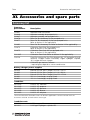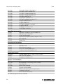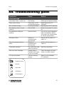
1
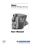
Tetra Personal Multigas Monitor User Manual M07237 November 2007 Issue 7 Safety information: • Read and understand all instructions in the operation section of this manual before use. 4. • Do not substitute components as this may impair intrinsic safety and invalidate warranty. • Observe all warnings and instructions marked on the unit and within this manual. • Observe site health and safety procedures for gases being monitored and evacuation procedures. 5. • Make sure you understand the screen display and alarm warnings. • If this product is not working properly, read the troubleshooting guide or call Crowcon. 6. • Ensure qualified service personnel change sensors and operating system. • Ensure maintenance and calibration are carried out in accordance with the procedures in the manual. 7. Instructions specific for use in hazardous areas The following instructions apply to equipment covered by certificate number: 8. BASEEFA03ATEX0193 The following information covers all relevant points listed in clause 1.0.6 of the EHSR’s of the ATEX directive. 1. The certification marking is as follows: 9. (-4°F to +131°F). The equipment should not be used outside these ranges. Compliance with the Essential Health and Safety Requirements has been assured by compliance with EN50014:1997 + Amds 1 & 2, EN50020:2002 and EN50018:2000, as certified by Baseefa. Compliance with gas detection performance standards EN50054, EN50057, EN61779-1, EN61779-4, EN50104 and EN50270 has been certified by Lloyd’s Register. Repair of this equipment and gas sensor replacement shall be carried out by the manufacturer or in accordance with the applicable code of practice. If the equipment is likely to come into contact with aggressive substances, then it is the responsibility of the user to take suitable precautions that prevent it from being adversely affected, thus ensuring that the type of protection is not compromised. The rechargeable battery must only be charged in non-hazardous (safe) areas by connection to the specified Crowcon charger power supply. Only the following cell types may be fitted in the battery compartment of the non-rechargeable battery pack: Duracell MN1500 LR6 Varta 4006 Ever Ready Energizer LR6 GP Batteries 15A LR6 1.5V The cells must only be changed in a non-hazardous (safe) area. The equipment is not certified for use in atmospheres containing more than 21% oxygen. Area Classifications: Zone 1: An area classified as Zone 1 is likely to have ignitable concentrations of flammable gases, vapours or liquids present under normal operating conditions. Zone 2: An area classified as Zone 2 is not likely to have ignitable concentrations of flammable gases, vapours or liquids present under normal operating conditions. Crowcon Detection Instruments Ltd 2 Blacklands Way, Abingdon OX14 1DY UK Tel. +44 (0)1235 557700 Fax. +44 (0)1235 557749 www.crowcon.com Email: [email protected] 2. The equipment may be used in zones 1 and 2 with 3. group IIA, IIB, and IIC flammable gases, temperature classes and vapours T1, T2, T3 and T4 with rechargeable battery option and classes T1, T2 and T3 with non-rechargeable battery option. The equipment is certified for use in ambient temperatures in the range –20°C to +55°C © Copyright Crowcon Detection Instruments Ltd 2007. All rights are reserved. No part of the document may be photocopied, reproduced, or translated to another language without the prior written consent of Crowcon Detection Instruments Ltd. Publication number: M07237 Seventh edition: November 2007 Tetra Personal Multigas Monitor Contents Unpacking ................................................1 Quickstart guide ........................................2 Introduction ..............................................6 Operation ..................................................8 Batteries ..................................................12 Alarm indications ....................................14 Fixing accessories ....................................15 Flow sampling ........................................16 Maintenance and calibration....................21 PC interface and software........................23 i-module replacement ..............................24 Specification ............................................26 Accessories and spare parts ....................27 Troubleshooting guide ............................29 Appendix: Limitations of sensors..............30 Tetra Unpacking Tetra Personal Multigas Monitor Thank you for purchasing the new Tetra Personal Multigas Monitor. Tetra has redefined portable gas monitoring and will give you years of unparalleled service and reliability. Please read the instructions carefully before use. Keep the manual for future reference. Unpacking Remove the Tetra Personal Multigas Monitor from the packaging. The Tetra accessories will be located in the bottom of the box. Check the contents are complete, you should have: • Tetra unit; • Optional battery charger power supply for units supplied with rechargeable Li-ion batteries; • A configuration report detailing the sensors installed, alarm settings and a calibration certificate; • Optional accessories such as flow adaptor and aspirator bulb; • Optional spare battery pack for non-rechargeable units. Battery check The Tetra Personal Multigas Monitor has two battery options: Li-ion rechargeable or alkaline non-rechargeable batteries. Depending on the battery option chosen, the Tetra will operate for a minimum of 12 hours and up to 18 hours when fully charged. Rechargeable units Tetra uses a Li-ion battery pack and should arrive with sufficient charge so that the unit can be used straight out the box. However, if this is the first time you have used the Tetra unit, you may need to charge the batteries to attain the full 12 to 14.5 hour operating time. (The actual operating time will depend on the types of sensors installed.) Warning: rechargeable units Do not attempt to use any other charger power supply, with this unit except the one supplied by Crowcon. Failure to comply could invalidate safety certification and may result in permanent damage to the unit. 1 Quickstart guide Tetra Quickstart guide 1. Getting started Review your Tetra unit Top view Alarm LEDs IR comms window Operator button Operator LCD display screen Side view Belt clip lever Front plate Switching on your unit Tetra requires little setting up, follow these simple steps to get your unit ready for use. 1. Ensure the unit is in clean air. 4s 2. Switch on Press and hold the operator button until the red LED flashes. The operator display screen will light up and the unit will begin a warm up sequence. 2 Tetra Quickstart guide Tetra warm up sequence a) The unit will test the alarm LEDs, sounder, vibration alerts, and the operator display screen. The sounder may be silenced by pressing the button. LEDs Alarm test Sounder Alarm test Vibrator Alarm test b) The unit will continue through a warm up sequence as shown below, this will take approximately 45 seconds. CROWCON Tetra Tetra vs. 1.01 CH4 NEXT CAL i %LEL CO Gas Detection You .. ppm 21-Aug-2003 ppm O2 Wed 14-May-2003 14:02:49 1-2 m AUTO ZERO? i H2S TODAY IS i % Click to confirm in 7 secs ! c) Auto zero If auto zero is enabled (default), the unit will display the auto zero menu. Press the operator button with a single click to confirm auto zero. If the operator button is not pressed within the 10 second time out, Tetra will proceed directly to Run mode without performing zero. Auto zero AUTO ZERO? i AUTO ZERO AUTO ZERO Click to confirm in 7 secs 0.0 CH4 H2S Co O2 0.0 CH4 H2S Co O2 No auto zero CH4 %LEL CO ppm OK 20.9 0.0 H2S ppm 0 0.0 O2 % Run mode 3 In the event of an alarm Tetra Run mode Your unit is now ready to use. Below is a typical screen display showing the unit in normal gas monitoring Run mode. CH4 %LEL CO ppm O2 Warm up OK OK 20.8 0.0 H2S ppm 0 0.0 Screen Icons % Familiarise yourself with the gases being monitored in your unit and make sure you understand site health and safety procedures in the event of alarm conditions. Tetra units with an inbuilt pump will produce a low humming noise, this is normal. Flashing icon, Tetra running normally Pump Battery Auto zero Confidence signals In normal Run mode, Tetra will emit a short beep every 10 seconds and the OK icon flashes to show operational health. 2. In the event of an alarm Alarm signals In the event of gas concentrations exceeding the alarm thresholds for any gas being monitored, Tetra will activate the alarm signals. Alarm signals Alarm icon The red and blue alarm LEDs will flash, the sounder will emit a loud, fast series of beeps, the internal CH4 %LEL CO ppm 2 vibrator alarm will 0 0.0 activate. The 16.7 0.0 H2S ppm O2 % operator screen will display the gas in alarm and the alarm level. See the figure to the left. Gas example under alarm 4 Tetra Switching off 1. When the gas level returns to normal, press the operator button. This will reset your Tetra unit to normal Run mode. If gas levels are still in alarm, the button will have no effect. The Tetra alarm is set to latch by default. The unit will still continue in alarm mode even when gas levels return to normal, until the alarm is cleared, by pressing the operator button. For any one gas, there are normally two alarm thresholds. These are indicated by the alarm icons shown. 1 2 3. Switch off unit and storage Switching off unit 1. Press and hold the button for 5 seconds. The shut down menu appears, continue to hold button until the unit counts down to shut off. CH4 %LEL CO OFF IN 0.0 ppm OK 0 4 sec 20.8 0.0 H2S ppm O2 % Storing conditions In order to optimise sensor performance and lifetime, your Tetra unit should be stored in a safe, non-hazardous area, 0-30°C, 10-90%RH. 4. Additional information For For For For For battery recharging information go to section III. fixing accessories go to section V. sampling section go to section VI. calibration information go to section VII. troubleshooting guide go to section XII. 5 Introduction Tetra I. Introduction Thank you for purchasing the new Tetra Personal Multigas Monitor. Tetra is a portable multigas detector, designed to be carried or worn by individuals working in hazardous environments such as confined spaces. It is suitable for use in Zone 1 and 2 hazardous areas. Tetra can monitor up to four different gases and display the readings simultaneously on a display screen. Alarm warnings are given through a combination of a loud audible alarm, a bright visual alarm of blue/red flashing LEDs and an internal vibrator. Tetra can be fitted with a wide range of modular, plug and play gas sensors. Each sensor carries an intelligent processor which contains calibration and sensor information. Tetra is battery operated and is available with rechargeable and non-rechargeable battery options. The rechargeable unit contains its own internal charger, a battery charger power supply is available for 110 V or 230 V a.c. see section XI for more information. At Crowcon we recognised the need for a reliable and robust confined space personal monitoring system, which is both lightweight, compact, easy to use and cost effective. Tetra has a single operator button, and an intelligent userfriendly display with automatic backlight. Gas levels are continuously monitored providing normal gas readings, peak readings and time weighted averages (TWA). Tetra is available as a diffusion sampling instrument or with built in electric sampling pump. Configuration and data/event logging is handled by Crowcon Portables PC software, the PC communication link being provided through a fast, reliable optical link. Tetra’s shape and design makes it comfortable to wear and as non-intrusive as possible, with a non-slip grip for better handling. Extra accessories, such as shoulder strap and chest harness, can be purchased. Tetra has been designed from top to bottom to bring you a revolution in ease of use, maintenance and extreme reliability. Through innovative and rigorous design technology, we have introduced several new features. i-module gas sensor Tetra uses unique plug and play i-module sensor technology. Each sensor unit incorporates its own intelligent processor holding sensor configuration and calibration data. Different sensors can be purchased, and once inserted, are immediately ready to run. Tetra can operate with up to four sensors and display simultaneously, information and gas readings, for all the sensors, on one screen. This means no redundancy and assured future investment in your Tetra unit, 6 Tetra Introduction allowing you to swap sensors between units or configure your unit, as appropriate, to your current needs. Plug and play will ease maintenance time and cost, and the intelligent modular system will remove the need to calibrate each sensor. Additional i-modules can be purchased, pre-calibrated from your local supplier. Reliable, anti-shock mechanics and robust housing The Tetra housing is built from resilient material, giving it strength and flexibility to withstand the hardest of working conditions, water and dust tight to IP65, and with a non-slip grip. The internal structure has been carefully designed to make servicing easy and at the same time very rugged. If the unit is dropped, there will be no disruption of power or function, ensuring reliability and service for years to come. Software The internal software in Tetra has been designed and written in accordance with the requirement of IEC 61508 to ensure quality and integrity of operation. Tetra has been designed to give a truly reliable personal gas monitoring system. The internal circuitry includes an external watchdog, the software monitors for any malfunction within the unit and will display an error warning to the user should they occur. 7 Operation Tetra II. Operation 2.1 Switch-on sequence 1. Ensure the unit is in clean air. 2. Switch on Press and hold the operator button until the red LED flashes. The instrument begins with testing all the LCD segments on the operator display screen, the red and blue alarm LEDs, sounder and internal vibrator alert for about 5 seconds. The sounder may be silenced by pressing the button. The unit enters a warm up mode and displays a sequence of screens, see page 3 for more details. At the end of warm up, the auto zero menu will be displayed. The auto zero function can be disabled or set to run automatically, without user confirmation: autozero menu will not appear. See section VIII PC Interface and software. Battery check Use this time to check there is sufficient charge in the battery pack ! NB. During the warm up sequence, the date for next calibration will be displayed. If the date has expired or has passed, the Tetra unit will display a warning message that calibration is due. The instrument can still function, but it is strongly recommended the unit is sent for calibration as soon as possible. Tetra can be set, using the Portables PC software, for the instrument to shut down automatically, if the calibration date is passed, to prevent further operation of the instrument. 3. Auto zero menu Press the operator button with a single click to confirm auto zero. If the operator button is not pressed within 10 seconds, Tetra will proceed directly to Run mode without performing a zero. Flammable and toxic sensors will be set to read zero and the oxygen sensor to read 20.9%. NB. If auto zero fails, a warning message will be displayed and an ‘X’ will appear against the sensor that has failed. Switch off To switch off the unit, press and hold the operator button for 5 seconds. A shut-down menu ‘OFF IN’ will appear, continue to hold button until the unit counts down to shut off. 8 Tetra Run mode 2.2 Run mode The Tetra unit will display up to four gas readings simultaneously on the operator display screen. A typical display with four sensors installed, is shown below. CH4 %LEL CO 20.8 0.0 ppm OK 0 0.0 H2S ppm O2 Screen Icons Warm up OK Flashing icon, Tetra running normally Pump % Battery Each channel will display the gas name, units and current value. Familiarise yourself with the gases currently being monitored in your unit. Ensure you understand site health and safety procedures. For information on peak and TWA readings, go to section 2.4. Auto zero Confidence signals To reassure users the unit is working correctly, the Tetra unit will emit a short beep every 10 seconds and the OK icon will flash. The pump is running correctly when the icon is revolving. 2.3 Display symbol guide Battery Full ! A full battery is represented by a battery icon showing a full six bars. A low battery charge will show 1 to 2 bars. When zero bars are shown the battery icon flashes. The sounder will emit warning bleeps. If the battery becomes too low, Tetra will display a ‘Battery low’ warning message and switch off. Internal pump This revolving icon indicates the internal pump is running. If the pump or airway becomes blocked, the unit will emit a warning sound and display a warning message. Check the flow adaptor and sample lines are free from dirt or water, and that the sample line is not kinked or blocked. Restart pump by pressing the operator button. 9 Display options Tetra TWA alarm Tetra will display the TWA alarm when the 15 minute or 8 hour time weighted average alarm threshold is passed for toxic gases. 2.4 Display options Tetra provides two additional selectable displays: Peak display When Peak mode is selected the instrument shows the highest value for flammable and toxic gases and the lowest value for oxygen since the mode was selected. This is useful for vertical entry checks where the whole instrument can be lowered down the shaft rather than just a sampling tube. Deselecting Peak mode clears stored peak information. TWA display Shows the 15 minute or 8 hour time weighted average (TWA), for toxic gases, monitored since last turn on. 1. To view the additional display option menu, double-click the operator button. CH4 %LEL CO ppm Gas 0 Peak 0.0 TWA20.8 OK 0.0 H2S ppm O2 % 2. Press the operator button with a single click to scroll through the list. When your choice is highlighted, double-click the operator button. Peak display 1. Scroll 2. Select ppm OK 0 Gas Peak 0 TWA 20.8 % The Tetra operator screen will display the peak or TWA icon and the gas readings recorded. 10 Tetra Logging Peak test When performing a peak test, such as a vertical entry check, previous readings can be cleared on entry to the peak display option. Zero The Tetra instrument can perform an autozero by selecting the Zero function from the menu. When zero is completed, the instrument will return to normal operation. 2.4 Logging Tetra incorporates event logging which can be accessed using the IR communications link with Portables PC software. See section VIII. Tetra records the time and date for a number of operating and diagnostic events including: • Switch on and switch off • Level 1, Level 2 and Time Weighted Average Alarms, alarm on, alarm off and the peak level during the alarm • Zero, calibration and gas test with success or failure • Pellistor saver on and off • The battery condition is logged every 15 minutes while the instrument is operating, and certain configuration changes are also logged. 11 Batteries Tetra III. Batteries 3.1 Rechargeable batteries Recharge time for the Li-ion batteries is less then 6 hours (less, if they are not fully discharged). Rechargeable batteries will typically last 12+ hours, fully loaded with 3 or 4 sensors and a pump. Charging the batteries 1. Ensure you are in a safe area. 2. Plug the charger power supply into a mains socket. 3. The charging socket is located on the bottom of the unit: there is a small cover which can be opened to reveal the socket, (see figure below). Pull back the cover and insert the lead into the socket. Switch on the power. The unit would normally be left switched off for charging and will display a battery icon on the display sweeping from empty to full. When charging is complete a full battery icon flashes on the screen. If the unit is switched on during charge the normal display battery icon sweeps from empty to full. On disconnecting the charger power supply this display icon will update in 20 seconds to show actual charge state. The unit is fully charged when the charging battery icon is flashing, Battery fully charged Tetra warning message Battery full WARNING i Low battery 25 Battery needs recharging The charging time will be longer if the unit is switched on during charging. 12 Tetra Batteries (see example). In Run mode, the battery icon will display six bars when it is full. 4. Remove the lead from the charging socket and replace the protective cover. 3.2 Non-rechargeable batteries Tetra uses a three AA alkaline battery pack which will give 11 hours operating time. The following battery types are suitable for the non-rechargeable version: Energizer type LR6 MN1500 Gold Peak type 15A LR6 Duracell type MN1500 LR6 Varta type 4006 Alkaline batteries will typically last 11 hours. To replace the battery pack, ensure you are in a safe, non-hazardous area. The battery pack is located in the bottom of the instrument. Remove the access cover and withdraw the battery pack. Replace the 3 x AA cells, then reinsert the pack into the instrument and replace and securely fasten the access cover. 13 Alarm indications Tetra IV. Alarm indications Tetra provides two instantaneous alarm levels for each installed sensor, designated level 1 and level 2. For toxic gas sensors, there are also two time weighted average alarms (TWA), one for short term exposure (STEL): based on a 15 minute time weighted average, and the second TWA alarm is for long term exposure: based on a 8 hour time weighted average. Alarm configurations are set via the Crowcon Portables PC software. The following settings can be made: Alarm thresholds for each sensor: Level 1 1 2 and level 2 alarms can be set for each individual gas sensor. Alarm type: This can be set to rising levels of gas concentration, or as falling. Oxygen are set to falling for deficiency monitoring. Alarm latching: Alarms can be set to be latched or unlatched. Latched alarms will require the operator button to be pushed in order to clear the alarm. This is the default setting. Unlatched alarms will clear automatically when the gas hazard has passed. Alarm mute: The sounder can be set to mute for level 1 alarm only; pressing the operator button during an alarm condition ie presence of hazardous gas, will silence the sounder and stop the vibration alarm. The alarm LEDs will continue to flash. Alarm sounder tone: Different tones can be selected to achieve the best performance for the monitoring conditions available. In the event of a Time Weighted Alarm (TWA) In the event the 15 minute or the 8 hour TWA is triggered, Tetra will go into alarm and display the TWA icon with the toxic gas readings. The 8 hour TWA alarm cannot be cleared. 14 Tetra Fixing accessories V. Fixing Accessories Belt clip Tetra has a strong built-in belt clip located on the back of the unit. Lifting the small lever will allow the unit to be attached to a belt more easily. Universal harness plate Crowcon provide a universal harness plate which can be used with either a chest harness or a shoulder strap. Belt clip lever Shoulder/neck connectors Lever Waist connectors How to wear your Tetra unit Chest harness Slide the universal harness plate over the belt clip at the back of your Tetra unit. The plate will lock automatically into place. Create a chest harness by attaching one strap to the top connectors, to go around the neck, and the other to link around the waist using the side connectors. Adjust the lengths until the Tetra unit is in a comfortable working position. Shoulder strap With the universal harness plate in place on the belt clip, attach the shoulder strap accessory onto the top connectors. Adjust to a comfortable working position. See accessories, section XI, for full list. 15 Flow sampling Tetra VI. Flow sampling Attaching the flow adaptor plate To perform manual sampling using Tetra, a flow adaptor plate must be fitted onto the front of the instrument. Flow adaptor Gas in Gas out 1. To fit the flow adaptor plate, slide the top of the flow adaptor plate into the small recess on the front of the instrument, screw the thumbscrew until the plate is tightly fitted into place. 2. Attach the sampling tube or flow accessory onto the gas inlet nozzle. 3. Non- Pumped (diffusion) instruments Attach the aspirator bulb onto the gas outlet nozzle. 4. To remove the flow adaptor plate, unscrew the thumbscrew and lift the plate away from the instrument. The sampling tube supplied is normally a 2m (6ft) length. Longer lengths of sampling tube can be provided, but will increase the time taken to get a sample from the point of sampling to the Tetra instrument. When using an extended length of tubing a response time test is recommended. Gas of known concentration should be sampled along the full length of tubing to be used and the time taken for the sensor reading to reach the known gas levels should be noted. This time should be used as the minimum for sampling before readings should be taken. 16 Tetra Flow sampling Pumped instruments Tetra’s inbuilt pump draws sample air in through the inlet nozzle of the flow adaptor plate and out through the outlet nozzle. When using sampling equipment, if the inlet should become blocked with dirt, water or a kink in the line, the pump will automatically stop. Tetra will emit a rapid series of beeps and display a warning message. To restart the pump, clear the blockage and press the operator button. Extension probes, drop lines and water traps are available. See accessories section XI. Diffusion instruments When using the manual aspirator kit, adopt a consistent style whilst using the hand aspirator. Crowcon recommend squeezing once per second to achieve a flow rate of approximately 0.5 - 1 litre/min. At least 10 pumps per sample are recommended. 17 Gas testing Tetra Tetra gas test accessory kit The Gas Test Accessory is a gas testing kit designed to enable gas testing of the Tetra multigas detector using a specially formulated, high stability long life quad gas mix. It can be used with Tetra units having sensors for Flammable, Oxygen, Carbon Monoxide and Hydrogen Sulphide gases, and all Tetra units with these sensors can be gas tested using the kit. 6.1 Gas testing Gas testing checks the sensor is responding within set limits to an applied gas of known composition. This can be performed as often as desired, but would usually be carried out each time the Tetra is issued for use. The Tetra itself will determine Pass/Fail status for the gas test. In order to perform successful gas tests ensure: • The quad gas mixture used has the correct gas concentration, and that it is within the validity date specified by the supplier. • The gas flow path is leak tight. It is important to check that the flow plate is properly fitted to the Tetra, and the outlet tubing is not restricted in any way, nor additional tubing length used. The Gas Test Accessory Kit is supplied in a convenient carry case and comprises; a gas cylinder containing the quad gas mix, a 'Trigger' regulator with interconnect tubing, a magnet - used to activate Test mode, an aspirator plate to attach to the Tetra and a vent line. The Trigger regulator can be operated in two ways: (1) squeeze and hold - allows gas flow as long as the lever is held in, or (2) by lifting the lever - the flow is locked on. There are two versions of the kit; one for pumped Tetra units and one for non-pumped Tetra units supplied with an aspirator plate. Pumped Tetra units require the use of the plate with the integral bellows assembly. 6.2 How to perform a gas test 1. Ensure your Tetra unit is switched on and in normal operation. 2. Clip the flow plate onto the front of the unit and attach the hose from the Trigger regulator. Attach the outlet hose to ‘vent gas away’ - do not extend this hose and do not restrict or allow kinks. 3. Swipe the magnet passed the display adjacent to the LED lens. Your Tetra unit will activate the Gas Test and show ‘GAS TEST’ on the display. 18 Tetra Field calibration 4. Tetra will display a progress bar at the bottom, the names of the gas sensors fitted are shown with a cross beside each. Operate the Trigger regulator and apply gas to the Tetra whilst the progress bar is counting down. As gas flows and the sensors respond, the Tetra monitors the response against stored gas values. Provided the response reaches a predefined window around each gas value within the test time the cross by each sensor will change to a tick and the unit passes the test If any sensor response fails the test the Tetra will display a message advising the unit be sent for calibration. 6.3 How to perform a field calibration test To perform a field calibration test, you must first Zero your Tetra unit 15 minutes or less before commencing the gas test instructions. 1. Follow steps 1 to 3 given in 6.2, Tetra will display an alternate screen message; Calibrate? Click to Confirm In 10 seconds 2. Press the button within 10 seconds to confirm Calibration. If the button confirmation for calibration is not made within 10 seconds then the process will revert to gas test as in 6.2. 3. Apply calibration gas following step 4 in 6.2. Tetra will display a progress bar at the bottom, the names of the gas sensors fitted are shown in reverse image with a cross beside each. Operate the Trigger regulator and apply gas to the Tetra whilst the progress bar is counting down. As gas flows the Tetra allows the sensors to respond and then adjust the value for each gas channel to match the stored calibration gas value within each sensor i-module. Provided all channels calibrate successfully within the allowed time the calibration will be designated successful. If any channel does not calibrate successfully it will remain marked with a cross and screen a message ‘Gas test failed’ and ‘Send for calibration’ will be displayed. A tick will appear against each channel as the unit passes the test 4. To abort the Calibration test press the button at any time whilst the test is in progress. 19 Gas test/calibration troubleshooting Tetra 6.4 Cal/Test This can arise if having selected and confirmed calibration one or more (but not all) of the sensors are not calibrate enabled. In this case calibrate enabled channels will calibrate, and non-enabled channels will Gas Test (bump) only. Oxygen i-modules are usually not set to calibrate enabled as the calibration at 20.9% on atmospheric air during the zero process is more accurate and repeatable than using certified gas mixtures. Provided it completes a successful test and the other i-modules fitted successfully calibrate the calibration due date for oxygen will be reset during a Cal/Test. 6.5 Gas test/calibration troubleshooting Symptom Possible Cause Action No response to gas Gas cylinder empty Check gauge, replace cylinder as needed Hose blocked or kinked Ensure no restriction to flow Gas cylinder empty Check gauge, replace cylinder as needed Gas cylinder out of date Check date and replace as needed Hose blocked or kinked Ensure no restriction to flow Calibration drifted Calibrate Tetra Gas flow not started immediately Repeat test, starting gas immediately Gas cylinder empty Check gauge replace bottle as needed Gas cylinder out of date Check date and replace as needed Hose blocked or kinked Ensure no restriction to flow Calibration drifted Calibrate Tetra Stabilisation time too short Reset using PC software Menu Zero not performed Tetra not field calibration version Select Zero from menu Send for re-configuration Tetra fails gas test Tetra fails calibration Tetra passes gas test but will not enter calibration mode Note: Remove regulator from gas cylinder when not in use over a prolonged period. For parts list, see section XI. 20 Tetra Maintenance and Calibration VII. Maintenance and Calibration Tetra is designed to operate almost maintenance free under most conditions. However, some small items of routine maintenance are recommended. General To keep the display panel and operator button free from dirt build up, regularly wipe over your Tetra unit with a damp cloth. Filter Inspect the front filter at regular intervals for dirt or damage. Replace with a new filter/front grill if necessary, part number CO1852. Zero and calibration Tetra is supplied with an auto zero function on start-up. This function can be configured to operate automatically, on user confirmation (see quick start guide), or can be disabled. This configuration can be set with the Crowcon Portables PC software, see section VIII. Tetra also has a zero function in the menu. See section 2.4. Crowcon recommends, as a minimum, a monthly gas test to confirm sensor operation. A test gas of known composition, needs to be applied, to verify sensor response and alarm function. Instrument calibration of all sensors should be performed at 6 month regular intervals. Calibration method Tetra calibration can either be performed using the Portables PC software or by use of the Gas Test Accessory Kit. Using the Portables PC software allows calibration using either single gas mixtures, and calibrating each sensor in turn, or using a multigas mixture for simultaneous calibration. The Gas Test Accessory Kit allows calibration on a quad gas mixture for the standard 4 gas combinations of flammable, oxygen, carbon monoxide and hydrogen sulphide. Calibration and Gas Testing require the use of the correct type of flow plate as follows: Non pumped units - use either the standard flow plate or the clip on calibration flow plate C011005 Pumped units with software version 1V07 or lower. The pump is 21 Maintenance and Calibration Tetra always running even in Calibration or Gas Test modes - it is essential to use the C01874 'bellows' style flow plate. Pumped units with software version 1V08 or later where the default configuration is that the pump is automatically switched off in Calibration or Gas Test mode. Use the clip on calibration flow plate C011005 unless the default configuration has been changed to maintain the pump running for Calibration or Gas Test in which case it is essential to use the C01874 'bellows' style flow plate. 22 Tetra PC interface and software VIII. PC interface and software Tetra can be connected to a PC using an infrared optical link. The Tetra unit has an optical communication port: an IR window is located on the top of the unit. The PC requires a Crowcon infrared PC interface, part number MIS26003 and Crowcon Portables PC software. The adaptor connects to an RS232 port, a USBRS232 adaptor is also available from Crowcon. The software provides the user with access to reconfigure alarm levels, operation, run calibrations, print reports and to access the event log. Set-up 1. Install Portables PC software on PC and install infrared adaptor. Warning The infrared communications are not IrDA. DO NOT install IrDA drivers, if supplied with with the IR link kit. 2. Switch on the Tetra unit and move to within range of the adaptor. 3. Open the Portables PC software and either use the Wizard or the Engineer’s Form, select Tetra and upload the configuration. For more information on using the Crowcon Portables PC software, see installed help file. 23 i-module replacement Tetra IX. i-module replacement 1. Ensure you are in a non-hazardous (safe) area. Switch off the unit 2. Remove any accessories, such as the flow adaptor, if fitted. 3. Remove the front cover grill by unscrewing the M3, 2 mm Allen screw as shown the in the drawing, point Unscrew the side retaining M4, 3 mm Allen screws as shown in . Remove the three sensor plate retaining screws as shown by point . Ease the top away from the body, point . Press down lightly on the rubber seal protecting the sensor housing and slide forward, to clear the internal chassis from the sensor plate aperture. With care, withdraw the whole instrument assembly. Removing an installed i-module 1. Locate the i-module connection ribbon, squeeze the two retaining lugs, on the module board, toward each other and pull out slightly, this will release the ribbon. 2. Remove the retaining ring from the clips. Unclip the i-module from the 4. 5. 6. 7. 24 Tetra i-module replacement two quick release fixings, push the sensor mounting out the sensor plate housing, taking care to retain any seals. Installing or replacing an i-module If replacing an i-module with one of the same type, instrument specific configuration will be retained. If replacing with a different i-module its default configuration will be loaded. 1. Unwrap the i-module from any packaging, ensure the sensor is fully seated on the module board. If you are installing a new i-module into a currently unused slot, you will first need to remove the dummy i-module. Follow the i-module removal instructions to do so. 2. Ensure the gasket is in place on the sensor, push the sensor through the sensor aperture in the sensor plate housing. Click the quick release fixings around the i-module board, ensuring the i-module is held in place firmly and the sensor is still tightly located on the module board. Replace the retaining ring on the clips. 3. Attach the ribbon connector by squeezing the two retaining lugs , on the module board, toward each other and pulling out slightly. Slide the ribbon, with the metal connectors facing away from the board, into the slot. Push the retaining lugs back toward the sensor, this will grip the ribbon firmly. Warning Do not twist the connection ribbons. Do not pull the sensor housing assembly too far from the PCB board, to prevent damage to the cabling or electrical connections. Re-assembling the Tetra unit 1. Ensure the connection ribbons and cables are tucked in. Slide the whole assembly back into the casing. Ensure all gaskets are in place. Replace the top and front cover grill. 2. Switch on your Tetra unit. The new sensor will be automatically identified. Check the filters and gaskets are all in good condition. Replace if any items are faulty. Refer to the troubleshooting guide if necessary. 25 Specification Tetra X. Specification Dimensions 122 x 128 x 57 mm (43/4 x 5 x 21/2 inches) Weight 498 g rechargeable unit, including belt clip and 4 sensors. Housing, degree of protection Ingress protection IP65 (NEMA 4) Operating temperature -20°C to +55°C (-4°F to +131°F) Humidity 0-99% RH, non-condensing for continuous operation Display 128 x 64 pixel Warm up time 45 seconds approximately Response time (typical) (T90) : appx 20 seconds for most toxic sensors, 10 seconds for oxygen. Repeatability ±2% FSD, 6 months Explosion protection Intrinsically Safe ATEX Essential Health and Safety Requirement, clause 15.9 Safety certificate no. BASEEFA03ATEX0193 Approval codes Europe: USA: Canada: ATEX II 2G EEx ia d IIC T4, (Tamb –20°C to +55°C) Class I Division 1, Groups A, B, C and D. Class I Division 1, Groups A, B, C and D T4. Standards Safety: USA: Canada: Operation Marine Equipment Directive 96/98/EC 26 EN50014, EN50020, EN50018, 94/9/EC UL913 CSA22.2, 152 EN50270, EN50271, IEC61508 Tetra can be supplied Wheelmarked compliant with the Marine Equipment Directive. Contact Crowcon to obtain a copy of the MED certificate Tetra Accessories and spare parts XI. Accessories and spare parts Accessory list Crowcon part number C01841 C01846 C01847 C01876 C01877 C01893 C01874 C01875 C011005 C03328 Description Aspirator Plate and Gasket Aspirator assembly for pumped units Aspirator assembly, non pumped units Tetra Gas Test Accessory Kit for pumped units Tetra Gas Test Accessory Kit for non-pumped units. Refer to Section VII for applicability Tetra Gas Test Accessory Kit. Refer to Section VII for applicability Calibration Flow Plate for pumped units. Refer to Section VII for applicability Calibration Flow Plate for non-pumped units. Refer to Section VII for applicability Calibration Flow Plate. Refer to Section VII for applicability. Quad Gas mixture for Gas Test Accessory Kit, 34 litre bottle 50%LEL methane, 250ppm carbon monoxide, 15ppm hydrogen sulphide, 18% oxygen balance nitrogen. Calibration gas contact Crowcon - required gases depend on sensor combination Battery charger power supplies E01839 External PSU for Tetra Charger, UK 230 V 50 Hz E01866 External PSU for Tetra Charger, US 110 V 60 Hz E01841 External PSU for Tetra Charger, Euro 230 V 50Hz E01860 230 V in line charger, no plug fitted. E01861 110 V in line charger, no plug fitted. i-modules: S011424* S011436* S011437* S011439* S011440* 0-100% 0-100% 0-100% 0-100% 0-100% LEL LEL LEL LEL LEL methane propane pentane butane ethylene *There are alternative flammable sensors for different applications. Contact Crowcon with the instrument Serial No. to check correct sensor type. i-modules cont: S011423 S011421 0-25% oxygen O2 0-100 ppm hydrogen sulphide H2S 27 Accessories and spare parts S011422 S011425 S011426 S011427 S011428 S011429 S011430 S011431 S011432 S011433 S011434 S011435 S011438 0-500 ppm carbon monoxide CO 0-20 ppm sulphur dioxide SO2 0-10 ppm nitrogen dioxide NO2 0-20 ppm nitrogen dioxide NO2 0-20 ppm chlorine Cl2 0-1000 ppm hydrogen H2 0-25 ppm hydrogen cyanide HCN 0-5 ppm phosphine PH3 0-1 ppm ozone O3 0-10 ppm hydrogen fluoride HF 0-1 ppm fluorine 0-100 ppm ammonia NH3 0-1000 ppm ammonia Sampling accessories: C01847 Aspirator assembly for non pumped units C01757 Telescopic aspirator probe C01097 3 foot Sample probe M04032 Aspirator hose (please specify length in feet) C03141 6 m Drop line C01245 Water trap Carrying and wearing: C01842 Universal harness plate C01843 Shoulder strap C01844 Chest harness strap kit C01845 Carry case, rechargeable units C01888 Carry case, non-rechargeable units Communications: MIS26003 Infrared adaptor for PC, plugs into RS232 port C02097 USB to RS232 adaptor C01832 Portables PC Software CD Spares / consumables: E01541 Alkaline battery, AA (3 required) S011330 Rechargeable Li-ion battery pack assembly C01851 Aspirator bulb S011398 Sensor filter assembly C01853 Dummy sensor module M04787 Rubber sealing bung for charger socket M04482 i-module O-ring seal M04431 Sensor clip retaining ring For calibration gases consult Crowcon 28 Tetra Tetra Troubleshooting guide XII. Troubleshooting guide Symptom/ error message Cause Action Instrument won't switch on Pump not running Flat battery. The pump is a PC configurable option. Function disabled. Zero drifted. Recharge or replace battery. Reconfigure with PC software. Reconfigure with PC software. Restart instrument in clean air. Do not use; exit hazardous area immediately. Return instrument for recalibration or sensor replacement. Switch off and restart in clean air. No confidence beep Gas reading when no gas present Unstable/inaccurate gas reading Autozero failed Cannot autozero due to alarm Calibration expired Flow fail clear blockage LCD too faint/dark Sensor failure Zeroing in contaminated atmosphere Zeroing in contaminated atmosphere The calibration due date has passed Sample tube is blocked with water or dirt or kinked Contrast setting wrong Switch off and restart in clean air Send for calibration Clear blockage and press button to restart pump Adjust using Portables PC software. Fatal/Auto shut Service User alert Calibration Configuration 29 Appendix: Limitations of sensors Tetra Appendix: Limitations of sensors Sensor limitations The sensors used in Tetra have limitations common to all such gas sensors, and users should be aware of the points listed below. Crowcon can advise on particular situations and suggest alternative sensors if the instrument is likely to experience extreme conditions. Tetra uses a catalytic flammable gas sensor, which measures the flammability of the gas. For this reason, readings displayed on the unit will be unreliable over concentrations of approximately 120% LEL. Oxygen is necessary for catalytic sensors to operate. A 'pellistor saver' is used to disconnect power to the pellistor sensor in the event of over-range to prevent burn out. This locks out for 200 seconds after which a button press will reconnect power to the pellistor. If the sensor power is reconnected when the unit is exposed to an over-range gas concentration there is a risk of damage to the pellistor sensor. Restart should be carried out in a known fresh air environment. Depleted oxygen levels can reduce the flammable gas reading, and if oxygen levels are below safe breathing limits it should be assumed that the flammable reading is low. Electrochemical gas sensors contain chemicals. Extreme levels of humidity can also cause problems. The sensors are rated for an (average) ambient of 15-90% R.H. However they are used from the tropics to deserts to tundra without this normally being a problem. Water should not be allowed to collect on the sensors as this may impede gas diffusion. Persistent exposure to high levels of toxic gas will shorten the life of toxic sensors. If the high level gas is corrosive (e.g. hydrogen sulphide) damage may occur over time to metal components. Sensors may be cross sensitive to other gases. If unsure, contact Crowcon or your local agent. 30 Thank you for reading this data sheet. For pricing or for further information, please contact us at our UK Office, using the details below. UK Office Keison Products, P.O. Box 2124, Chelmsford, Essex, CM1 3UP, England. Tel: +44 (0)1245 600560 Fax: +44 (0)1245 808399 Email: [email protected] Please note - Product designs and specifications are subject to change without notice. The user is responsible for determining the suitability of this product.