1
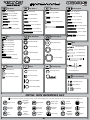
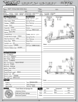
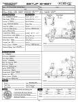
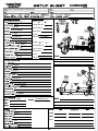
8IGHT-E 2.0 Race Roller Vehicle Setup
2 degrees of toe out
27mm
Differentials
Front: x Standard
Smart
Spring Wire Dia:
-1 degree
Qty of Springs:
Stock(20 degrees)
Ramp Plate:
2.3mm
Grease:
54/40wt Losi
Diff Fluid: Losi 5000wt
Silver 4.4lbs
See shock length
95mm
Long
Center: x Standard
Spring Wire Dia:
Qty of Springs:
Down
Ramp Plate:
2/B
Grease:
2/Inside
Smart
Diff Fluid: Losi 5000wt
3 degrees
3 degrees
29mm
-2 degrees
Back
2.3mm
56/25wt Losi
Green 3.1lbs
See shock length
106mm
2/B
2/Inside
Losi 2000wt
Xcelorin 2100Kv
45
15
0%
Normal
4%
20%
6.0v
4S 5000mAh Lipo
(Recommended)
Notes:
High
3%
34
Back Cover
UNITED STATES:
4710 E. Guasti Road
Ontario, CA 91761
Phone: 909-390-9595
Fax: 909-390-5356
UNITED KINGDOM:
Units 1-4 Ployters Rd
Staple Tye
Harlow, Essex
CM18 7NS
Phone: +44 (0) 1279 641 097
WWW.LOSI.COM
E-mail - [email protected]
800-0385
14822
Front Cover
®
1/8-SCALE 4WD COMPETITION ELECTRIC BUGGY RACE ROLLER
OWNER’S MANUAL
INTRO
q STEP I-01
Intro to the 8IGHT-E 2.0™ Manual
Welcome Team Losi Racing 8IGHT-E 2.0 Owner!
Thank you for selecting the 8IGHT-E 2.0 as your new racing buggy. The 8IGHT-E 2.0 has already distinguished itself as a top caliber racing chassis and
as you will see, we have made every effort to produce a vehicle that is not only the most competitive but also easy to maintain. The simple step-by-step
assembly sequence and easily followed instructions and drawings combined with Team Losi Racing's world famous quality fitting parts will make using
the 8IGHT-E 2.0 a most enjoyable vehicle.
Please take a moment to read through the following instructions. This will familiarize you with the various parts, assembly tips and descriptions as
well as the tools needed. Taking an extra moment before using your vehicle will help you understand the dynamics of the 8IGHT-E 2.0 and setup tips to
ensure the best possible experience.
Good luck and good racing,
Team Losi Racing
Register your Losi Product Online:
Register your 8IGHT-E 2.0 now and be the first to find out about the latest options parts, product updates and more. Log on to www.LOSI.com
and follow the product registration link to stay connected.
8IGHT-E 2.0 COMPLETED KIT SPECIFICATIONS
Overall Chassis Length: 16.35" (415mm)
Wheelbase: 12.71"-12.87" (323-327mm)
*Front Track Width: 12.13" (308mm)
Overall Length w/Tires: 19.5" (497mm)
*Overall Height: 6.625" (168mm)
*Rear Track Width: 12.13" (308mm)
Note: Final vehicle weight will vary depending on accessories used.
*All measurements taken at ride height (32mm).
Table 1: 8IGHT-E 2.0 Completed Vehicle Specifications.
Vehicle/Manual Organization:
where steps are repeated (front/rear or left/right) these numbers may be
omitted. Please note that these numbers will not call out every sub-step
required for the step’s assembly procedures, they will only highlight the
critical order required for assembly.
In each step, there are specific “Detail Icons” (shaped like a stop sign) that
call out critical precautions or assembly tips for the process. There is a
reference key that describes the meaning of each of the icons located on
the fold-out Hardware Identification Guide at the back of this manual.
To ensure that parts are not lost during construction, it is recommended
that you work over a towel or mat to prevent parts from rolling away.
The vehicle is composed of different steps marked A through H. Each
step contains all of the parts necessary to complete a particular section
of the vehicle. Some of these steps have sub-assembly steps within them.
It is helpful to read through the instructions for an entire step prior to
working on your vehicle. Next to each of the step numbers is a check box.
At the completion of each step, place a check in this box so that if you
must stop and come back to the assembly, you will be able to pick up
where you left off.
For your convenience, an actual-size Hardware Identification Guide is
included as a fold-out page at the back of this manual. Hardware that
is not easily differentiable in each step is called out with an icon which
contains a small picture of the part genre (referenced on the Hardware
Identification Guide), the quantity of that part required for what is shown
in the step, and the size or name of that part. To check a part, hold it
against the silhouette until the correct part is identified. Associated with
each of these parts, in the Hardware Identification Guide, is an LOSANumber which is used when
ordering replacement parts
for your 8IGHT-E 2.0. In some
cases, extra hardware has been
supplied for parts that may be
easy to lose.
Components used in each step
are identified by their relative LOSA-Number and the component’s
name. With the exception of a few parts, these are not referenced in the
Hardware Identification Guide.
The molded parts in Team Losi Racing vehicles are manufactured to
demanding tolerances. When screws are tightened to the point of
being snug, the parts are held firmly in place. For this reason, it is very
important that screws not be overtightened in any of the plastic parts.
In some steps there will be a filled black circle with a white number.
These indicate the specific order by which assembly must occur. In cases
IMPORTANT SAFETY NOTES:
1.Select an area for assembly that is away from the reach of small
children. Some parts in this vehicle are small and can be swallowed
by children, causing choking and possible internal injury; PLEASE USE
CAUTION!
2.The shock fluid and greases supplied should be kept out of
children’s reach. They are not intended for human consumption!
3.Exercise care when using any hand tools, sharp instruments, or
power tools during construction.
4.Carefully read all manufacturer’s warnings and cautions for any
chemicals, glues, or paints that may be used for assembly and
operating purposes.
i
Differentials
Front: Standard
Smart
Spring Wire Dia:
Qty of Springs:
Ramp Plate:
Grease:
Diff Fluid:
Center:
Standard
Smart
Spring Wire Dia:
Qty of Springs:
Ramp Plate:
Grease:
Diff Fluid:
Notes:
32
HARDWARE
Cap Head
Flat Head 1
2-56 x 1/4" (A6232)
Flat Head 2
3 x 8mm (A9106)
2-56 x 1/2" (A6254)
Button Head
2-56 x 1/4" (A6255)
8-32 x 3/8" (A6264)
4-40 x 1/4" (A6234)
3 x 12mm (A3500)
4-40 x 3/8" (A6206)
4-40 x 1/2" (A6204)
4-40 x 5/8" (A6221)
5-40 x 3/8" (A6277)
4mm x 12mm (A6259)
5-40 x 1/2" (A6271)
5-40 x 1/2" (A6240)
4-40 x 1/2" (A6256)
8-32 x 1/2" (A6262)
5-40 x 3/8" (A6270)
5-40 x 1/2" (A6278)
5-40 x 5/8" (A6275)
5-40 x 20mm (A6281)
5-40 x 1-7/8" (A6273)
5-40 x 3/4" (A6272)
5-40 x 7/8" w/ 5/8" Shoulder (A4414)
600-0157
5-40 x 3/4" (A6279)
5-40 x 1" (A6280)
5-40 x 7/8" (A6273)
8-32 x 3/4" (A6263)
Set
Ball Bearings 1
F 5-40 x 1/8" (A6228)
Ball Bearings 2
5x10x4mm (A6949)
C 4-40 x 1/8" (A6227)
5x13x4mm (A6949)
Pins
C 5-40 x 3/16" (A6299)
6x10x3mm (A6946)
C 8-32 x 1/8" (A6298)
2.5 x14mm (A3526)
F 5-40 x 1/8" (A6297)
8x14x4mm (A6945)
F 8-32 x 1/8" (A6296)
2.5 x 12.37mm (A3523)
3 x 17mm (A3531)
5x11x4mm (A6947)
O10-32 x 3/8" (A6295)
2.5 x 12.8mm (A3505)
1/2” x 3/4" (A6953)
5-40 x 22mm (A6045)
F 5x11x4mm (A6948)
600-0162
4 x 66mm (A6500)
Washers
Shims
Ball Stud (A6215)
Retaining Clips
5x7x.2mm (A9104)
3.5 x 53mm (A6503)
5mm E-clip (A6109)
#4 x .030" (A6350)
6x11x.2mm (A3501)
.250 x .094 x .020" (A9166)
Nuts (Lock/Plain)
650-0052
Body Clip (A8200)
14x17x.1mm (A4452)
650-0053
#4-40 (Mini) (A6306)
650-0054
#5-40 (A6302)
14x17x.25mm (A4452)
650-0053
#8-32 (A6311)
650-0054
DETAIL ICON REFERENCE KEY
1
LOSI-LOK
These numbers are used to identify the critical order in which assembly must occur. *Note: They will not call out every stage of the assembly process.
Apply Losi-Lok®
Pay Special
Attention
L
Side
Shown
GREASE
CUT
LL
RR
Apply High
Pressure Black
Grease
GLUE
Cut/Trim
Assemble
Other
Side the Same
x2
Apply CA Glue
Degrease with
Motor Spray
Ensure Free
Movement
Ensure Free
Rotation
Repeat/Build
Multiple
Screw Partially
33
OIL
Fill With
Silicone Oil
Pre-Tap
Ensure Proper
Orientation
Push Firm
DO NOT
Over Tighten/
Snug Tight
Tighten
INTRO
TOOLS REQUIRED FOR ASSEMBLY
Team Losi Racing has supplied all necessary Allen wrenches and special wrenches that are needed for assembly and adjustments. The following
common tools will also be required: needle-nose pliers, regular pliers, hobby knife, scissors or other body cutting/trimming tools, and a soldering iron
may be necessary for radio installation. 3/16", 1/4", 5/16" and 11/32" nut drivers are optional.
RADIO/ELECTRONICS
A suggested radio layout is provided in this manual. Your high-performance RC center should be consulted regarding specific questions pertaining to
radio/electrical equipment.
HARDWARE IDENTIFICATION
When in question, use the Hardware Identification Guide at the back of this manual.
• For screws, the prefix number designates the thread size and number of threads per inch (e.g., 4-40 is a #4 size thread with 40 threads per inch).
The second number, or fraction, designates the length of the screw. For cap head and button head screws, this number refers to the length of the
threaded portion of the screw. For flat head and setscrews, this number refers to the overall length of the screw.
• Bearings and bushings are referenced by the inside diameter (I.D.) x outside diameter (O.D.).
• Shafts and pins are designated by type (Roll, Solid) and referenced by diameter x length.
• Washers, Spacers and Shims are described by inside diameter or the screw size that will pass through the inside diameter x the thickness or by their
designated application (e.g., Ball Stud washer is primarily used under a Ball Stud).
• Retaining Clips are sized by the shaft diameter that they attach to or by type (Body). The Hardware Icon associated with E/C-clips only designates
the part genre of clips, not the actual part.
• Nuts come in four types, Non-Flanged, Flanged (F), Plain and Locking (L) (designated on the Hardware Icons). The prefix number designates the
thread size and number of threads per inch. The second number, or fraction, designates the size of the hex. For example, L 4-40 x 1/4" designates a
locknut that will thread onto a 4-40 screw using a 1/4" nut driver.
• Setscrews come in three types, Cup (C), Flat (F) and Oval (O) (designated on the hardware Icons). The prefix number designates the thread size and
number of thread per inch. The second number, or fraction, designates the length of the threaded portion of the screw.
TABLE OF CONTENTS
SECTIONS
TABLES
1.INTRODUCTION...................................................... i
Vehicle/Manual Organization............................. i
Important Safety Notes....................................... i
Tools Required for Assembly............................. ii
Radio/Electronics............................................... ii
Hardware Identification..................................... ii
2.Step A: Steering Assembly................................... 1-2
3.Step B: Front Clip................................................ 3-8
4.Step C: Center Transmission.............................. 9-11
5.Step D: Rear Clip............................................. 12-17
6.Step E: Shocks................................................. 18-20
7.Step F: Radio Tray........................................... 21-24
8. Step G: Tire and Wheel Installation................. 25-26
9.Checklist Before Your First Run.........................27
10.Setup Guide..................................................... 28-29
11.Warranty Information.................................... 30-31
12.Blank 8IGHT-E 2.0 Setup Sheet..........................32
13. Hardware Identification Guide............................33
14.Filled-out 8IGHT-E 2.0 Vehicle Setup Sheet.......34
Table 1: 8IGHT-E 2.0 Completed Vehicle Specifications.i
Table 2: Servo Installation................................................... 21
Team Losi Racing is continually changing and improving designs; therefore, the actual part may appear slightly different than the illustrated part. Illustrations of parts
and assemblies may be slightly distorted to enhance pertinent details.
ii
STEP A
q STEP A-01
q STEP A-02
Steering Link Assembly
Servo Saver Assembly
x1
x1
A9168
A9166
Steering
Servo
Steering
Servo
ArmArm
4-40 x 1/2"
A6256
A4423
Servo Saver Tube
L 4-40 x 3/16"
A6306
Maintenance Tip
A6043
A6045
Rod
End
Ball
Rod
Ball
End
A6043
A6045
Rod End
Rod End
LOSI-LOK
x1
L 4-40 x 3/16"
A6306
x1
5-40 x 7/8"
A6045
A4423
Steering Arm
A4412
Steering Drag
Link
x1
4-40 x 1/2"
A6256
A4412
Drag Link Screw
A4406
Steering Bell
Crank R
A4406
Steering Bell Crank L
A4423
Servo Saver Spring
2.26"
57.40mm
q STEP A-03
Tighten the Servo Saver
nut all the way down and then
back it off 2 1/2 turns.
A4423
Saver Nut
Chassis and Motor Brace Assembly
A4462
Motor Brace
x3
L 5-40 x 1/4"
A6302
A4413
Front Chassis
Support
A4404
Chassis
A4408
Steering Post
LOSI-LOK
x1
8-32 x 3/8"
A6264
x4
5-40 x 1/2"
A6721
LOSI-LOK
1
STEP A
q STEP A-04
Steering/Top Plate Assembly
A4424
Front Body Mount
x1
5-40 x 1/2"
A6271
LOSI-LOK
A4413
Front Chassis Brace
x2
5-40 x 1/2"
A6278
x1
5-40 x 3/8"
A6270
LOSI-LOK
x4
6x10x3mm
A6946
q STEP A-05
Completed Steering Assembly
2
STEP B
q STEP B-01
q STEP B-03
Ring Gear Assembly
Complete Diff Assembly
A3503
Outdrive Cup
Solid
x1
Fill with 5000 wt oil just above the
planetary gear
2.5 x 12.80mm
A3518
1
x4
3x12mm
A3500
3
2
x1
F 8x14x4mm
A6948
A3509
Ring Gear
4
A3505
O-ring
A3502
Sun Gear
x2
A3505
Diff Seal
6x11x0.2mm
A3501
q STEP B-02
A3502
Planetary Gear
Diff Case Assembly
A3502
Planetary Gear
Axle
Solid
x1
2.5 x 12.80mm
A3518
A3503
Outdrive Cup
x1
F 8x14x4mm
A6948
3
Tighten the diff screws
in this order
1
1
4
2
A3500
Diff Housing
4
x2
A3502
Sun Gear
A3505
O-ring
6x11x0.2mm
A3501
3
3
2
STEP B
q STEP B-04
Front Diff Install
x1
F 8-32 x 1/8"
A6296
To prevent fine dust from entering the
gearbox, apply a thin bead of grease
along the edge of the case as pictured.
3
LOSI-LOK
4
x2
A3514
Drive Adapter
5x11x4mm
A6947
1
6
2
x2
5-40 x 7/8"
A6273
A4427
Front Diff Case
A3508
Pinion Gear, Bevel
5
x2
5-40 x 1/2"
A6240
A4427
Front Diff Cover
q STEP B-05
Front Spindle & CV Assembly
A3535
CV Driveshaft
Solid
1
A3523
CV Couple
x1
2.5 x 12.4mm
A3518
A1707
Left Spindle
3
x1
1/2” x 3/4"
A6953
2
x1
A3522
Axle
8x14x4mm
A6945
4
Solid
x1
3 x 17mm
A3518
6
A3530
Wheel Hex
x1
C 8-32 x 1/8"
A6298
5
7
LOSI-LOK
4
STEP B
q STEP B-06
Spindle/Carrier Assembly
x1
O 10-32 x 3/8"
A6295
A1709
Left Spindle Carrier
A6501
Hinge Pin
x2
A1703
Left Front Arm
8/32 x 3/4"
A6263
5
2
4 4
A1701
Front Arm Bushing
x2
1
5
C 5-40 x 3/16"
A6299
3
3
2
q STEP B-07
Front Suspension Arms Assembly
A4431
Front Inner Hinge
Pin Cap
A1744
Front Inner Hinge
Pin Brace
Solid
x2
4 x 65mm
A6500
x4
5-40 x 3/4"
A6272
A4431
Front Outer Hinge
Pin Cap
A1744
Front Outer Hinge
Pin Brace
5
STEP B
q STEP B-08
Sway Bar Assembly
A1750
Sway Bar Link
Install the Sway Bar Ball onto the Sway Bar Wire until the
end of the wire is flush with the ball as pictured above.
A1750
Sway Bar Ball
A1750
Sway Bar Mount
Cap
x2
4-40 x 5/8"
A6221
x2
A1750
Sway Bar, 2.3mm
C 4-40 x 1/8"
A6227
A1750
Sway Bar Ball
x4
x2
C 5-40 x 1/8"
A6228
2-56 x 1/4"
A6232
q STEP B-09
Tie Rod/Shock Tower Assembly
A6055
6.8mm Flanged
Suspension Ball
A1714
Front Shock Tower
Be sure to install the assembled Tie
Rod onto the car with the groove
(next to the center square section)
on the driver’s left side for easier
adjustment later.
A6542
4mm Turnbuckle, Front
x2
A5438
Shock Standoff
x2
L 5-40 x 1/4"
A6320
L 8-32 x 11/32"
A6311
A6046
Rod End
A4453
Shock Tower
Mount Cap
A6056
6.8mm Suspension Ball
x4
5-40 x 1/2"
A6278
A6057
Camber Standoff
x1
5-40 x 1"
A6280
x2
5-40 x 3/4"
A6279
3.71"
94.25
6
STEP B
q STEP B-10
Center CV Assembly
Solid
x1
2.5mm x 14mm
A3518
A3526
CV Coupling, Center
1
2
LOSI-LOK
x1
A3526
Driveshaft, Front
Center
q STEP B-11
F 5-40 x 1/8"
A6228
Steering Rod Assembly
Be sure to install the assembled Tie
Rod onto the car with the groove
(next to the center square section)
on the driver’s left side for easier
adjustment later.
A6050
Steering Ball
A3537
Grease Boot
3
x1
5-40 x 5/8"
A6275
A6542
Steering Turnbuckle
A6050
A6046
Steering Ball
A6046
Steering Rod End
Steering Rod End
A6542
Steering
Turnbuckle
A6050
Steering Ball
x1
3.62"
92.00mm
5-40 x 1/4"
A6302
7
STEP B
q STEP B-12
Front Clip Assembly
x2
5-40 x 3/4"
A6279
x2
5-40 x 3/4"
A6272
4
1
A4453
Front Bulkhead Spacer
3
2
x4
8-32 x 1/2"
A6262
A4422
Front Bumper
q STEP B-13
Completed Front Assembly
8
STEP C
q STEP C-01
q STEP C-03
Ring Gear Assembly
Solid
Complete Diff Assembly
x1
2.5 x 12.80mm
A3518
Fill with 5000 wt
oil just above the
planetary gear.
3
x4
3x12mm
A3500
A3502
Sun Gear
1
2
4
A3506
Center Outdrive
x2
x1
6x11x0.2mm
A3501
F 8x14x4mm
A6948
A3505
O-ring
A3505
Diff Seal
A3562
45T Plastic Spur Gear
A3502
Planetary Gear
Axle
q STEP C-02
Solid
Diff Case Assembly
A3502
Planetary Gear
x1
2.5 x 12.80mm
A3518
AA3500
Diff Housing
3
A3506
Center Outdrive
A3502
Sun Gear
2
4
1
Tighten the diff screws
in this order.
A3505
O-ring
x1
x2
1
F 8x14x4mm
A6948
3
6x11x0.2mm
A3501
9
4
2
STEP C
q STEP C-04
Center Motor Mount Assembly
x4
5-40 x 1/2"
A6271
LOSI-LOK
A4462
Diff Top Plate
A9198
Motor Mount
A4420
Center Diff Mount
q STEP C-05
Motor Installation
B9385
Pre-Assembled Motor
Leads, 1/8th Xcelorin
x1
8-32 x 1/2"
A6264
B9422
2100Kv Xcelorin Motor
LOSI-LOK
x1
#4 Countersink
A6351
LOSI-LOK
A9199
Motor Adapter
x1
x2
4mm x 12mm
A6259
Setscrew
A3575
10
A3575
1.0 Module Pitch Pinion, 15T
STEP C
q STEP C-06
Center Differential Installation
A4462
Center Diff Standoff Plate
x4
#8 Countersink
A6351
x2
8-32 x 3/8"
A6264
x4
8-32 x 1/2"
A6262
q STEP C-07
Completed Center Diff Assembly
11
STEP D
q STEP D-01
q STEP D-03
Ring Gear Assembly
Solid
Complete Diff Assembly
x1
2.5 x 12.80mm
A3518
A3502
Sun Gear
Fill with 2000 wt
oil just above the
planetary gear.
3
4
2
x4
3x12mm
A3500
x2
6x11x0.2mm
A3501
A3505
O-ring
1
A3510
Rear Ring Gear
A3505
Diff Seal
A3502
Planetary Axle
x1
F 8x14x4mm
A6948
A3503
Outdrive Cup
q STEP D-02
A3502
Planetary Gear
Diff Case Assembly
Solid
x1
A3502
Sun Gear
2.5 x 12.80mm
A3518
3
4
A3500
Diff Housing
Tighten the diff screws
in this order.
2
1
x2
4
6x11x0.2mm
A3501
1
A3505
O-ring
x1
A3503
Outdrive Cup
F 8x14x4mm
A6948
12
3
2
STEP D
q STEP D-04
Rear Diff Installation
x1
A4414
Rear Chassis Support
F 8-32 x 1/8"
A6296
x1
A3514
Drive Adapter
5-40 x 7/8"
A4414
LOSI-LOK
4
x2
A4451
Bearing Insert, LR
14x17x0.25mm
A4452
3
x1
14x17x0.10mm
A4452
5
x2
5x11x4mm
A6947
1
x1
L 5-40 x 1/4"
A6302
2
A4450
Rear Bulkhead
x2
5-40 x 7/8"
A6273
A3508
Pinion Gear
The 8IGHT-E 2.0 comes with (2) .25mm
shims and (1) .10mm shims on the left
bearing insert. On the right bearing insert
there are (3) .10mm shims. We advise that
you start with this gear mesh with your
new vehicle.
6
5
A4451
Bearing Insert, RR
x3
A4450
Rear Bulkhead Cover
q STEP D-05
14x17x0.10mm
A4452
7
Rear Hub & CV Assembly
A3523
CV Coupling
A3535
Driveshaft
1
Solid
x1
2.5 x 12.4mm
A3518
2
A1731
Left Rear Hub
3
x1
A3522
Axle
8x14x4mm
A6945
4
Solid
x1
3 x 17mm
A3518
6
x1
x1
1/2” x 3/4"
A6953
C 8-32 x 1/8"
A6296
A3530
Wheel Hex
5
7
LOSI-LOK
13
STEP D
q STEP D-06
Rear Suspension Arm Assembly
A1749
3 toe/3 Anti-Squat
Pivot Brace
x2
5-40 x 1-7/8"
A6273
A4431
Rear Outer Pivot
Brace Cap
Solid
x2
O 10-32 x 3/8"
A6295
x2
5/40 x 3/4"
A6272
x2
4 x 66mm
A6500
A1725
Left Rear Arm
A1745
Rear Pivot Brace
A6503
3.5mm Hinge Pin
A4431
Rear Inner Pivot
Brace Cap
x1
L 5-40 x 1/4"
A6302
A4453
Hub Spacer .050”
q STEP D-07
Sway Bar Assembly
A1750
Sway Bar Link
A1750
Rear Sway Bar, 2.3mm
A1750
Sway Bar Bar, Arm
x2
4-40 x 5/8"
A6221
x2
5-40 x 1/8"
A6297
x4
A1750
Sway Bar Ball
2-56 x 1/4"
A6232
Install the Sway Bar Ball onto the Sway Bar Wire until the
end of the wire is flush with the ball as pictured above.
14
x2
C 4-40 x 1/8"
A6227
A4453
Sway Bar Mount Cap
STEP D
q STEP D-08
Wing Mount Assembly
A4435
Wing Mount Brace
A4435
Right Wing Mount
x4
x2
5-40 x 3/4"
A6279
L 5-40 x 1/4"
A6302
A4435
Left Wing Mount
x3
5-40 x 1/2"
A6278
A4424
Rear Body Mount
x2
L 8-32 x 11/32"
A6311
A5438
Shock Stand-Off
A1735
Rear Shock Tower
q STEP D-09
Rear Shock Tower Installation
x2
5-40 x 3/4"
A6279
x2
5-40 x 1/2"
A6278
15
STEP D
q STEP D-10
Tie Rod Installation
A6055
6.8mm Suspension Ball, Flanged
x1
A6544
4mm Rear
Turnbuckle
5-40 x 3/4"
A6279
A6542
Rod End
x2
5-40 x 1/4"
A6302
x2
A6056
6.8mm
Suspension Ball
L 5-40 x 1/4"
A6302
x1
5-40 x 1"
A6280
3.79"
96.25
q STEP D-11
Center CV Assembly
Solid
x1
2.5mm x 14mm
A3518
A3536
CV Coupling, Center
x1
F 5-40 x 1/8"
A6297
4
2
1
LOSI-LOK
A3536
Driveshaft, Center Rear
3
A3537
Grease Boot
16
STEP D
q STEP D-12
Rear Clip Assembly
x2
L 5-40 x 1/4"
A6302
Caution! Ensure that the driveshaft
is inserted into the slot of the
center outdrive while installing the
Rear Clip assembly.
x4
x2
5-40 x 1/2"
A6240
q STEP D-13
Completed Rear Assembly
17
8-32 x 1/2"
A6262
STEP E
q STEP E-01
•
•
•
•
•
•
•
•
•
•
•
•
•
•
Shock Assembly
Clean the 2-56 x 1/4" Button Head Screw and apply Losi-Lok to the threads.
Install the #54 Shock Piston on the front shock shaft and a #56 Shock Piston on the rear shock shaft using the 2-56 x 1/4" Button Screw into the
Shock Shaft with a .050" Allen Wrench.
Place a drop of Shock Oil into the bottom of the Shock Body to lubricate the Shock Seals.
Thread the Shock Shaft into the Shock End using pliers. Used caution when threading the Shock Ends onto the Shafts. Avoid gouging or
scratching the Shock Shaft while gripping the Shock Shaft with pliers by placing the edge of a towel over the shaft, then gripping the portion of
the shaft covered by the towel. This method will work very well to protect the Shock Shafts from damage.
Ensure the Shaft is fully extended when filling the shock.
Fill the Front Shock Body with 40 wt Shock Oil and the Rear Shock Body with 25 wt until the oil is to the top of the body.
“Work” the Shock Shaft up and down 8 times. This will release the air bubbles trapped beneath the piston. Place the filled shock, in the upright
position, off to the side for a few minutes until the air bubbles escape from the oil.
Once all the air bubbles are out of the oil, gently place the Shock Bladder onto the shock as shown. Some oil should “bleed” from the shock.
Screw the Shock Cap onto the Body until some resistance is felt.
Slowly push the Shock Shaft up. This will bleed excess oil from the shock.
Tighten the cap all the way down using the shock tools included in your vehicle.
Move the Shock Shaft up and down. The shaft should be easy to push up into the body of the shock. If increased pressure is felt towards the top,
there is too much oil in the shock. Loosen the Shock Cap and “bleed” the shock as done previously.
Make sure each pair (front/rear) Shocks have the same rebound and compression. This is checked by holding one shock in each hand horizontally
and pushing them together by the Shock End. Watch carefully to ensure that both compress evenly. Now release both shocks and again watch
carefully as they should rebound the same.
Install the Shock Adjustment Nut O-ring into the Shock Adjustment Nut before installing the Nut onto the Shock Body.
x1
2-56 x 1/4"
A5440
Shock Piston
A5421
Shock Cap Bottom
LOSI-LOK
A5420
Shock Cap
#56
Shock Piston for
the Rear Shocks
#54
Shock Piston for
the Front Shocks
A5440
O-ring Shield
A5430
Shock Bladder
A5429
Shock Shaft O-ring
A5411
Front Shock Shaft
A5440
Shock Shaft Bushing
A5413
Rear Shock Shaft
A5429
Shock Shaft O-ring
A5429
Shock Bottom Cap
O-ring
A5401
Front Shock Body
A5403
Rear Shock Body
A5435
Shock End
A5435
Shock End Ball
A5424
Shock Adjuster Nut
O-ring
A5424
Shock Adjuster Nut
18
x2
x2
Front
Rear
STEP E
q STEP E-02
x2
x2
Front
Rear
Shock Boot & Spring Assembly
A5426
Shock Boot
A5451
Silver Front Spring
A5458
Green Rear Spring
A5435
Spring Cup
q STEP E-03
Front Shock Installation
A5435
Shock Mount Bushing
x2
L 5-40 x 1/4"
A6302
Tip: Ensure the open end of the shock cup
is facing the outside on the vehicle
x2
5-40 x 20mm
A6281
x1
C 4-40 x 1/8"
A6227
19
STEP E
q STEP E-04
Rear Shock Installation
x2
L 5-40 x 1/4"
A6302
Tip: Ensure the open end of the shock cup
is facing the outside on the vehicle
A5435
Shock Mount Bushing
x2
5-40 x 20mm
A6281
x1
C 4-40 x 1/8"
A6227
q STEP E-05
Completed Shock Assembly
20
STEP F
q STEP F-01
Chassis Guard Installation
A4432
Chassis Guards
x5
5-40 x 3/8"
A6270
q STEP F-02
Steering Servo Installation
A9167
Servo Horn Adapter
Servo Manufacturer, Make/Model
Servo
Spacer
Servo
Horn
No
94357Z, 94358Z, 94649Z, 94360Z,
94452Z, 94758Z, 94737Z, 94738Z
Yes
94102Z, 94112Z
Yes
Hitec
All
No
24T
Futaba
All (S9102 DOES NOT FIT)
No
25T
JR
All (DZ9100T/S Needs Spacer)
Sanwa
Airtronics
KO
Propo
PDS-2123, 2344, 2363, 2365, 2366
x4
4-40 x 1/2"
A6204
23T
x4
#4x.030"
A6350
23T
No
No
A4453
Spacer
x3
4-40 x 3/8"
A6206
23T
A4460
Switch Plate
(Blank)
Table2: Servo assembly and installation
A4460
Radio Box 8E
Airtronics® is a registered mark of Sanwa Electronic Instrument Co., Ltd., Osaka, Japan.
Futaba is a registered trademark of Futaba Denshi Kogyo Kabushiki Kaisha Corporation of Japan
KO PROPO® is a registered trademark of Kondo Kagaku Co., Ltd., Tokyo, Japan.
A4460
Servo Mount
21
STEP F
q STEP F-03
Receiver/Antenna Tube Assembly
A4403
Antenna Cap
A8313
Name Plate
A4402
Antenna Tube
A4460
Receiver Cover
x1
Body Clip
A8200
q STEP F-04
Radio Tray Installation
x2
8-32 x 3/8"
A6264
22
STEP F
q STEP F-05
Servo Horn Installation
Tip: If you are using a metal output splined
servo be sure to use Losi Lok on the screw.
Supplied with Servo
(not included)
Ensure the servo gear is centered
before attaching the Servo
Horns. This is best accomplished
by connecting the servo to the
radio system and setting the trim
to center.
q STEP F-06
ESC Installation
x4
4-40 x 1/2"
A6256
B9516
1/8 Scale Excelorin
Sensorless ESC
B9384
Battery Lead with EC5 Connector
Route Under
Wire Hooks
B9364
Switch, 1/8th Xcelorin
ESC Receiver Lead
Route Signal Wire and
Switch Wire through Clips
on Bottom
Speed Control Lead
to Receiver
BOTTOM VIEW
A4461
Battery Tray
B9368
Signal Wire, 1/8th Xcelorin
A4463
Battery Strap
23
Speed Control Lead
to Receiver
STEP F
q STEP F-07
Battery Tray Installation
x2
#8 Countersink
A6351
x3
8-32 x 3/8"
A6264
x1
5-40 x 1/2"
A6271
Speed Controller Lead Wire
(Connect to Channel 2 in
Receiver)
q STEP F-08
Completed Radio Tray and Battery Installation
24
STEP G
q STEP G-01
Tire Installation
LOSI-LOK
A3531
Wheel Hexes
LOSI-LOK
A3531
Wheel Hexes
q STEP G-02
Wing Installation
1
A8130
Wing Button
A8130
Rear Wing
2
x2
Body Clip
A8200
25
STEP G
q STEP G-03
Completed Chassis Assembly
q STEP G-04
Painting the Body
Painting:
Prepare the Lexan Body for painting by washing it thoroughly (inside and out) with warm water and liquid detergent. Dry the body with a clean,
soft cloth. Use the supplied window masks to cover the windows from the inside. A high-quality masking tape should be used on the inside of the
body to mask off any stripes, panels, or designs that you wish to paint on the body. Use acrylic lacquer or other paints recommended for Lexan
(polycarbonate). (NOTE: LEXAN RC CAR BODIES ARE MEANT TO BE PAINTED FROM THE INSIDE!) Apply paint to the inside of the Body. Remove the
masking tape for the next color and continue. Try to use darker colors first. If you use a dark color after a light color, apply a coat of white paint over
the lighter color before applying the darker color, or if you are painting over white, coat it with silver. This will help prevent the darker color from
bleeding through the lighter color.
Mounting:
The body is already cut out for mounting. However you will need to cut out the area for the pipe stinger. This should be done before you paint your
body so you can easily see where it exactly needs trimmed.
Stickers:
After the body is mounted, REMOVE THE PROTECTIVE FILM ON THE OUTER SURFACE, now you can apply the stickers.
26
CHECKLIST
BEFORE RUNNING YOUR NEW 8IGHT-E 2.0 OFF-ROAD RACING BUGGY for the first time, you should run down the following checklist in order and
complete the listed tasks. We’re sure you’re anxious to get out and run your new 8IGHT-E 2.0 now that it’s built, but please note that fine-tuning of the
initial setup is an essential part of building a high-performance racing buggy such as your new 8IGHT-E 2.0. Following this simple Checklist and the Team
Tips will help to make the first run with your new car much more enjoyable.
1. Breaking in the differential:
6. Charge a battery pack:
While holding the chassis with only the left side tires firmly on the
ground, give the car about one eighth throttle, for 30 seconds. The
right side tires should spin freely during this time. Repeat this with
only the right side tires held firmly to the ground, allowing the left
tires to spin. Repeat these steps at least two more times.
Charge a battery pack as per the battery manufacturer's and/or
charger manufacturer's instructions. Never plug the battery into the
speed controller backwards as this will damage the speed controller.
7. Adjust the electronic speed control (ESC):
Perform the setup/calibration between the ESC and Transmitter
follow these steps:
A) Turn on Transmitter
B) While turning on the vehicle Press and Hold the setup button,
notice the Yellow LED is now ON solid. When the Yellow LED is on
solid, you can release the setup button.
C) Using the throttle trigger pull Full Throttle until the Green LED is
ON solid
D) N
ext push the throttle trigger to Full Brake until the Red LED is
ON solid.
E) Now return the throttle trigger to the Neutral position and the
Blue LED will be ON solid.
F) Turn off the vehicle/ESC power switch.
G) Turn the vehicle/ESC back ON; you are now ready to use the ESC.
2. Check for free suspension movement:
All suspension arms and steering components should move freely.
Any binds will cause the car to handle poorly.
3. Set the ride height:
Set the ride height on your buggy so that the bottom of the chassis
is 27mm from the ground in front and 29mm in the rear by adjusting
the shock adjustment nuts, effectively increasing or decreasing preload on the springs. See the Setup Guide for additional information
on ride height adjustment.
4. Set the camber:
Adjusting the camber tie rod length changes the amount of camber.
Use the Losi wrench to adjust the tie rods once installed. Rotating
the tie rods towards the front end of the vehicle will shorten the
length, increasing negative camber. Rotating the tie rods towards
the back of the car will lengthen them, increasing negative camber.
Set the front tires to have 1 degree of negative camber and ensure
that they are adjusted equally, left to right. Set the rear tires to have
2 degrees of negative camber and ensure that they are adjusted
equally, left to right.
8. Set the transmitter steering trim:
The steering trim tab on the transmitter should be adjusted so
that the car rolls straight when you are not touching the steering
wheel/stick. If the servo and steering link were installed correctly,
the wheels should turn equally to the left and right. If this is not the
case, refer to Table 2 and ensure that the steering servo and horn
were properly installed. Also check the steering link length as noted
in Step A-01. Make sure the throttle trim is set so that the brakes are
not “dragging” in the neutral position.
5. Set the front toe-in:
Adjust the front steering tie rods so that when the servo is centered
on the transmitter, the front tires are both pointing slightly out with
2 degrees of toe-out. Refer to the Setup Guide for more information
on toe-in/out.
27
SETUP GUIDE
TIPS AND HINTS FROM THE TEAM
Before you start making changes on your 8IGHT-E 2.0 Off-Road Racing buggy, you need to make a few decisions. First of all, tires, and how they are set
up, have a tremendous impact on overall performance. Before you start making changes on the chassis setup, take a moment to observe a few of the
fastest cars at the track and what type of tire and inner liner they are running. You will find the best adjustment will become a personal decision based
on the “feel” that each of these adjustments yield. Never make more than one change at a time; if the change you made works adversely, or doesn’t
address your need, return to the previous position and try something else. Team Losi Racing development team has put hundreds of hours on the
8IGHT-E 2.0 to arrive at the setup we put in the instruction manual. If you find that you have lost the “handle” go back to the vehicle (stock) setup, as
this setup has proven to be reliable, consistent and easy to drive.
All of us at Losi are sure that you will find the 8IGHT-E 2.0 Off-Road Racing Buggy to be the most versatile and easiest car to drive fast, with great
consistency. We hope the information in the following guide helps you to enjoy your 8IGHT-E 2.0, and racing it, as much as we do. For the latest in
setup and accessory parts information, visit the Losi web site at: www.losi.com regularly. Please check the Losi web site periodically to find out new
setup information as we are always testing on all types of tracks and surfaces. Also note that there are many ways to set up a car. The rules we follow
can reverse sometimes with different driving styles or different setup styles, so test for yourself and you will find a set up that works right for you.
Droop:
Always measure the droop of the 8IGHT-E 2.0 with the shocks on the buggy. Droop is always measured from the center of the top shock mount to the
center of the bottom shock screw. More droop (travel) in the front will have more on-power steering and allow the buggy to roll more on the rear
when on throttle. More droop (travel) in the rear will increase off-power steering and allow the buggy to roll on the front when off throttle. More front
and rear droop will accelerate better in bumps when going straight, but can cause the buggy to traction roll in rough turns. Less front and rear droop
will slide over bumps better in turns and may be better on high-speed and high-traction tracks.
Front Camber Links:
The lower camber link locations on the tower have more camber gain (total camber change through the suspension travel). Running the camber
tie rod in the lower holes will increase off-power steering and make the vehicle more aggressive; however you may lose some consistency. More
camber gain is good on small tight tracks. We have found that running less camber gain in the front suits the car the best for consistency and steering
balance. On the 8IGHT-E 2.0 we offer a longer camber link on the spindle carrier. A longer front camber link will make the vehicle feel stiffer and
this will keep the buggy flatter with less roll and increase high-speed steering. A short front camber link will roll more and make the vehicle more
aggressive. Too short of a front link may make the vehicle feel twitchy.
Rear Camber Links:
The 8IGHT-E 2.0 now has only three camber locations on the rear tower, however, we have added another inside hole on the rear hub. The stock
camber link setup for the 8IGHT-E 2.0 is location #2 on the tower and B in the hub. By using a longer rear camber link you will have less roll and
improve stability and traction. A shorter rear camber link will have more roll and increase steering and better handling in the bumps. Running “A” in
the rear hub will generate more corner rotation entering the turn, but decrease steering on exit. Running “B” in the hub will be more stable entering
the turn and increase steering on exit.
Pistons:
Generally smaller hole pistons, #56, have stiffer damping, slower weight transfer, slower response, and will land large jumps better. Larger hole
pistons, #54, have softer damping, increased traction, quicker weight transfer/response, and bottom out easier off large jumps.
Shock Oil:
Lighter shock oil has more overall traction and responds quicker. Thicker oil has less overall traction and reacts slower. On high bite/smooth tracks,
thicker oil is easier to drive. Make sure you adjust oil when there is a drastic temperature change (20-25 degrees). If it gets cold outside you need to go
to lighter shock oil. If it gets hotter outside you need to go to thicker weight shock oil.
Front Toe:
You never want to run toe-in on the front of the 8IGHT-E 2.0. Front toe-in (longer steering rods) decreases steering response entering and in the
middle of the turn but will increase on power steering. Toe-out (shorter steering rods) increases steering response when entering the turn and
increases straight line stability, however, it will decrease on power steering.
Rear Toe-in:
The 8IGHT-E 2.0 is equipped with 3 degrees of toe-in per side. Less rear toe-in will increase the wheel base of the buggy and decrease forward
traction, but will increase top speed and side traction in the middle of a turn. More toe-in will increase forward traction, have more off-power steering
and less side traction.
Wheel Base:
The 8IGHT-E 2.0 is equipped with a long wheelbase. A shorter wheelbase (spacers behind the rear hubs) increases on-power traction, rear weight
transfer, and has more off-power steering. A shorter wheelbase is better on tight or slick tracks. A longer wheelbase (spacers in front of the rear hubs)
decreases off-power steering, is more stable, better in bumps, and has more on-power steering.
Sway Bars:
The 8IGHT-E 2.0 is equipped with 2.3mm sway bars on the front and rear. A thinner front sway bar increases front off-power traction, but has less onpower steering. A thicker front sway bar decreases front off-power traction making the steering smoother entering the turn, but has more on-power
steering. A thinner rear sway bar increases rear traction and decreases on-power steering. A thicker rear sway bar increases stability in the middle of
the turn and increases on-power steering. Thicker sway bars are more stable on high-speed, high-traction tracks.
28
SETUP GUIDE
Differentials:
The 8IGHT-E 2.0 comes equipped with 5000 wt in the front and center diff, and 2000 wt in the rear diff. Thinner front differential oil increases offpower steering, but if the oil is too thin the steering will become grabby and inconsistent. Thicker front differential oil increases off-power stability
and increases on-power steering. Thinner center differential has less forward drive, can unload more under acceleration and is easier to drive on
rough and slick tracks. Thicker center differential has more acceleration, increases on-power steering, and less off-power steering. Thicker center
differential is better on high bite/smooth tracks. Thinner rear differential has more corning traction and increases steering in the middle of the turn.
Thicker rear differential has less steering in the middle of the turn and more forward traction.
Shock Mounting Positions:
More inclined (moving the shocks in on the tower) has softer initial damping and is more forgiving. Less inclined (moving the shocks out on the
tower) makes the car more responsive and is better for technical tracks.
Ackerman:
A long Ackerman plate will have smooth off-power steering and is more forgiving. The long Ackerman plate will have more steering on-power. A
short Ackerman plate responds quicker and has more steering in the middle of the turn. A short Ackerman plate is better suited for tight technical
tracks.
Camber:
More negative camber in the front has more steering and is more responsive.
Less negative camber in the front will have less steering and will be smoother.
More negative camber in the rear will have less rear traction, but will increase on-power steering and will be less grabby in bumps. Less negative
camber in the rear will have more rear traction and make the rear of the buggy stay flatter, but if traction is lost it will be more violent. To ensure
your 8IGHT-E 2.0 has the correct camber we recommend using our Losi Camber Gauge (LOSA99172).
Gearing:
The stock gearing for the 8IGHT-E 2.0 is 15 tooth pinion with a 45 tooth spur gear. This gearing is recommended to be used with a 4S LiPo. If a 5S
Lipo is desired, gearing must be reduced down to 13 tooth pinion (LOSA3753). If you are running on a very large sweeping track a 16 tooth pinion
(LOSA3756) is recommended. See gear chart below for other KV rated motors and their recommended gearing.
8IGHT-E 2.0 w/45T Spur
8IGHT-E 2.0 Gear Ratio Chart
Recommended
Pinion
4S Li-Po
5S Li-Po
1300
17
15
1700
15
14
2100
15
13
2400
13
11
Pinion
Spur
Motor Kv
10
11
12
13
14
15
16
17
18
43
14.23
12.94
11.86
10.95
10.17
9.49
8.90
8.37
7.91
44
14.56
13.24
12.14
11.20
10.40
9.71
9.10
8.57
8.09
45
14.90
13.54
12.41
11.46
10.64
9.93
9.31
8.76
8.28
Battery Selection:
Team Losi Racing recommends using a Losi 14.8V 5000mAh 4S 25C Lipo (LOSB9864) with the 8IGHT-E 2.0 with its respective gearing. Generally with
a 4S 5000mAh LiPo in the 8IGHT-E 2.0 we have experienced up to 13 to 15 minutes of runtime however this varies with track size and the amount of
traction that is available. An 18.5V 4000mAh 5S 25C LiPo (LOSB9834) can be used to increase overall power however a lower gearing is required. On
small indoor tracks we have found that a 5S LiPo with a 1300KV(LOSB9420) motor geared at 13 tooth has offered good power with great drivability.
Outdrives and Traction:
When your 8IGHT-E 2.0 is new it will have a lot of chassis roll and be a little loose on throttle due to lack of friction in the out drives and crossbones.
After about 45-60 minutes of running, the 8IGHT-E 2.0 will gain traction and stability. Once your 8IGHT-E 2.0 is broken in, replacing the out drives
and crossbones with new parts will have more corner speed.
Bump steer:
Running the bump steer ball down you will have smoother steering in the middle of the turn. With the bump steer ball up, this will increase steering
in the middle of the turn.
Rear Squat:
The 8IGHT-E 2.0 comes with three degrees of anti-squat. Running less anti-squat will have less off-power steering and roll (side to side) more on the
rear. Less anti-squat will accelerate better in small bumps. More anti-squat will have more support (side to side) and be better on rough tracks with
big jumps.
Ride Height:
Measuring from a flat surface to the bottom face of the chassis, adjust the front of the chassis with 27mm of ride height and 29mm in the rear. We
have found the 8IGHT-E 2.0 handles best when the front ride height is 1mm to 2mm lower or at least level than the rear of the truck. To measure
your ride height properly we recommend using the Losi Ride Height Gauge (LOSA99173).
29
Warranty
Warranty Period
Horizon Hobby, Inc., (Horizon) warranties that the Products purchased (the “Product”) will be free from defects in materials and workmanship at
the date of purchase by the Purchaser.
Limited Warranty
(a) This warranty is limited to the original Purchaser (“Purchaser”) and is not transferable. REPAIR OR REPLACEMENT AS PROVIDED UNDER THIS
WARRANTY IS THE EXCLUSIVE REMEDY OF THE PURCHASER. This warranty covers only those Products purchased from an authorized Horizon
dealer. Third party transactions are not covered by this warranty. Proof of purchase is required for warranty claims. Further, Horizon reserves the
right to change or modify this warranty without notice and disclaims all other warranties, express or implied.
(b) Limitations- HORIZON MAKES NO WARRANTY OR REPRESENTATION, EXPRESS OR IMPLIED, ABOUT NON-INFRINGEMENT, MERCHANTABILITY
OR FITNESS FOR A PARTICULAR PURPOSE OF THE PRODUCT. THE PURCHASER ACKNOWLEDGES THAT THEY ALONE HAVE DETERMINED THAT THE
PRODUCT WILL SUITABLY MEET THE REQUIREMENTS OF THE PURCHASER’S INTENDED USE.
(c) Purchaser Remedy- Horizon’s sole obligation hereunder shall be that Horizon will, at its option, (i) repair or (ii) replace, any Product determined
by Horizon to be defective. In the event of a defect, these are the Purchaser’s exclusive remedies. Horizon reserves the right to inspect any and
all equipment involved in a warranty claim. Repair or replacement decisions are at the sole discretion of Horizon. This warranty does not cover
cosmetic damage or damage due to acts of God, accident, misuse, abuse, negligence, commercial use, or modification of or to any part of the
Product. This warranty does not cover damage due to improper installation, operation, maintenance, or attempted repair by anyone other than
Horizon. Return of any goods by Purchaser must be approved in writing by Horizon before shipment.
Damage Limits
HORIZON SHALL NOT BE LIABLE FOR SPECIAL, INDIRECT OR CONSEQUENTIAL DAMAGES, LOSS OF PROFITS OR PRODUCTION OR COMMERCIAL
LOSS IN ANY WAY CONNECTED WITH THE PRODUCT, WHETHER SUCH CLAIM IS BASED IN CONTRACT, WARRANTY, NEGLIGENCE, OR STRICT
LIABILITY. Further, in no event shall the liability of Horizon exceed the individual price of the Product on which liability is asserted. As Horizon has
no control over use, setup, final assembly, modification or misuse, no liability shall be assumed nor accepted for any resulting damage or injury. By
the act of use, setup or assembly, the user accepts all resulting liability.
If you as the Purchaser or user are not prepared to accept the liability associated with the use of this Product, you are advised to return this
Product immediately in new and unused condition to the place of purchase.
Law: These Terms are governed by Illinois law (without regard to conflict of law principals).
Safety Precautions
This is a sophisticated hobby Product and not a toy. It must be operated with caution and common sense and requires some basic mechanical
ability. Failure to operate this Product in a safe and responsible manner could result in injury or damage to the Product or other property. This
Product is not intended for use by children without direct adult supervision. The Product manual contains instructions for safety, operation and
maintenance. It is essential to read and follow all the instructions and warnings in the manual, prior to assembly, setup or use, in order to operate
correctly and avoid damage or injury.
Questions, Assistance, and Repairs
Your local hobby store and/or place of purchase cannot provide warranty support or repair. Once assembly, setup or use of the Product has been
started, you must contact Horizon directly. This will enable Horizon to better answer your questions and service you in the event that you may
need any assistance. For questions or assistance, please direct your email to [email protected], or call 888.899.LOSI(5674) toll free to speak
to a service technician.
Inspection or Repairs
If this Product needs to be inspected or repaired, please call for a Return Merchandise Authorization (RMA). Pack the Product securely using a
shipping carton. Please note that original boxes may be included, but are not designed to withstand the rigors of shipping without additional
protection. Ship via a carrier that provides tracking and insurance for lost or damaged parcels, as Horizon is not responsible for merchandise
until it arrives and is accepted at our facility. A Service Repair Request is available at www.horizonhobby.com on the “Support” tab. If you
do not have internet access, please include a letter with your complete name, street address, email address and phone number where you can
be reached during business days, your RMA number, a list of the included items, method of payment for any non-warranty expenses and a brief
summary of the problem. Your original sales receipt must also be included for warranty consideration. Be sure your name, address, and RMA
number are clearly written on the outside of the shipping carton.
Warranty Inspection and Repairs
To receive warranty service, you must include your original sales receipt verifying the proof-of-purchase date. Provided warranty
conditions have been met, your Product will be repaired or replaced free of charge. Repair or replacement decisions are at the sole discretion of
Horizon Hobby.
Non-Warranty Repairs
Should your repair not be covered by warranty the repair will be completed and payment will be required without notification or
estimate of the expense unless the expense exceeds 50% of the retail purchase cost. By submitting the item for repair you are agreeing
to payment of the repair without notification. Repair estimates are available upon request. You must include this request with your repair. Nonwarranty repair estimates will be billed a minimum of ½ hour of labor. In addition you will be billed for return freight. Please advise us of your
preferred method of payment. Horizon accepts money orders and cashiers checks, as well as Visa, MasterCard, American Express, and Discover
cards.
If you choose to pay by credit card, please include your credit card number and expiration date. Any repair left unpaid or unclaimed after 90 days
will be considered abandoned and will be disposed of accordingly. Please note: non-warranty repair is only available on electronics and
model engines.
30
Warranty
United States:
Electronics and engines requiring inspection or repair should be shipped to the following address:
Horizon Service Center
4105 Fieldstone Road
Champaign, Illinois 61822
All other Products requiring warranty inspection or repair should be shipped to the following address:
Horizon Product Support
4105 Fieldstone Road
Champaign, Illinois 61822
Please call 877-504-0233 or e-mail us at [email protected] with any questions or concerns regarding this product or warranty.
United Kingdom:
Electronics and engines requiring inspection or repair should be shipped to the following address:
Horizon Hobby UK
Units 1-4 Ployters Rd
Staple Tye
Harlow, Essex
CM18 7NS
United Kingdom
Please call +44 (0) 1279 641 097 or e-mail us at [email protected] with any questions or concerns regarding this product or warranty.
Instructions for Disposal of WEEE by Users in the European Union
This product must not be disposed of with other waste. Instead, it is the user’s responsibility to dispose of their waste equipment by handing it
over to a designated collection point for the recycling of waste electrical and electronic equipment. The separate collection and recycling of your
waste equipment at the time of disposal will help to conserve natural resources and ensure that it is recycled in a manner that protects human
health and the environment. For more information about where you can drop off your waste equipment for recycling, please contact your local
city office, your household waste disposal service or where you purchased the product.
Declaration of Conformity
(in accordance with ISO/IEC 17050-1)
No. HH20081229
Product(s):
Losi 8IGHT-E 2.0 RACE ROLLER
Item Number(s):LOSA0806
Equipment class:1
The object of declaration described above is in conformity with the requirements of the specifications listed below, following the provisions of the
European R&TTE directive 1999/5/EC:
EN 301 489-1 v.1.6.1
EN 301 489-17 v.1.2.1
General EMC requirements
Signed for and on behalf of:
Horizon Hobby, Inc.
Champaign, IL USA
Dec 29, 2008
Steven A. Hall
Vice President
International Operations and Risk Management
Horizon Hobby, Inc.
31