1
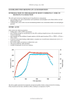
Sea Strainer Alarm Installation & Operating Instructions THE SCIENCE OF SILENCE Sea Strainer Alarm Installation & Operating Instructions 1 Contents Sea Strainer Alarm Fitting Instructions Section 1 1.1 1.2 1.3 2 3 4 4.1 4.2 4.3 5 5.1 5.2 5.3 5.4 5.5 5.6 5.7 5.8 6 6.1 6.2 6.3 6.4 6.5 Section 1 1.1 Page Introduction What it does Before you begin About these instructions Tools and fasteners Basic components and accessories Installing the components Fitting Sea Strainer Alarm Sensor(s) Fitting the Junction box/Control Unit Fitting the Display at the Helm Station Connections and wiring Control box terminals Display head wiring (common to all installations) Sensor wiring for single engine installations Sensor wiring twin engine installations Sensor wiring for generator set or third engine High intensity sirens Connecting to a power supply Fitting the OEM Junction box/control unit Functional Checks Electrical checks Before starting the engine With engine(S) running check Frost protection Function 2 2 3 3 3 4 5 5 6 7 7 8 8 9 9 9 10 10 10 11 11 11 11 11 11 Introduction What it does The Sea Strainer Alarm monitors the flow of water to the engine raw water-cooling pump, which has a flexible impeller. Marine engines use cold water from outside (also referred to as raw water) to cool the engine either directly by flowing through internal passages or indirectly through a heat exchanger or intercooler. The Sea Strainer Alarm is designed for use with inboard engines and is suitable for some outdrive/sterndrive installations. Check with Halyard technical department if in doubt. Should this water be blocked or substantially reduced, the boat’s engine raw water cooling pump impeller can quickly degrade (typically in less than 30 seconds) and the engine can then overheat and suffer damage. In extreme cases a fire may break out Common causes are a plastic bag caught in the inlet skin fitting, a blocked inlet strainer or forgetting to open a closed seacock (raw water inlet valve) prior to starting the engine. Sea Strainer Alarm Installation & Operating Instructions 2 1.2 By monitoring the flow of raw water directly, the Sea Strainer Alarm may therefore give early warning preventing subsequent engine damage. However, its sole purpose is to warn against engine raw water pump impeller damage. Before you begin Before you start, please read through these instructions carefully. Fitting the Sea Strainer Alarm involves: Cutting in to a section of flexible cooling water supply hose immediately after the sea strainer before the engine-cooling water pump. Installing the sensor in to the flexible hose with hose clamps. Mounting the Junction Box/Control Unit in a suitable location. Mounting the Helm Display or Displays. Wiring the system. CAUTION: If you have any doubts at any time about installing this equipment, please consult and qualified installer or contact Halyard directly. 1.3 About these instructions Bold text below sections will draw attention to SAFETY CONSIDERATIONS of adjacent text in accordance with the conventions of the Recreational Craft Directive. DANGER: Indicates a hazard that could EASILY result in death or serious injury if proper precautions are not taken. If you have any doubts about what precautions to take, you should seek expert advice. WARNING: Indicates a hazard that could result in death or serious injury if proper precautions are not taken. If you have any doubts about what precautions to take, you should seek expert advice. CAUTION: Indicates a hazard that could result in personal injury or damage to your boat or its equipment if suitable care is not taken. NOTE: Contains additional information that may be of help. Section 2 Tools & Fasteners The Sea Strainer Alarm can be installed with the average DIY toolkit. The only special equipment you might need is a wire-stripping tool. You will also need: A pair of side cutters - if you wish to shorten the overall cable lengths. Electrical tie-wraps or cable clips to secure the wiring to suitable supports. A small crosshead electrical screwdriver to fit the terminals on the control box. Spanners to fit hose barbs to the senor tee. Any tools required to remove and refit the section of water feed hose. Extra cable for the siren(s) if fitted. PYFE tape for the hose barb threads. CAUTION: We strongly recommend that a proper wire-stripping tool be used to remove insulation, thus avoiding the potential danger of a sharp blade. Sea Strainer Alarm Installation & Operating Instructions 3 Section 3 Basic Components & Accessories Standard Components Before you start, please check that your kit contains the following components. All components are supplied in sealed polythene bags. If you think you are short of any items, please call us immediately. Single engine – single helm station 1 x Sea Strainer Alarm Control Box with twin-core red and red/black wiring. 1 x Sea Strainer Alert sensor. 1 x Sea Strainer Alarm Helm Display, mounting bracket and attached wiring. This bag contains a smaller bag of screws and connectors. Twin engines – single helm station As for single engine, but with two Sea Strainer Alarm sensors. Triple engines (or two plus generator set) As for single engine, but with three Sea Strainer Alarm sensors. Accessories Please check you have any accessories you ordered with the standard kit. For example: Hose tails Additional Helm Displays 120dB siren(s) Any extra Sensors needed e.g. for a generator. If in doubt, seek advice BEFORE you start the job NOTE: Accessories are available individually and may be retrofitted at any time after initial installation. WARNING: The sirens supplied are very loud (120db). Activating or testing an upgraded siren could harm your hearing. Sea Strainer Alarm Installation & Operating Instructions 4 Section 4 Installing the Components 4.1 Fitting the Sea Strainer Alarm Sensor Screw two hose tails in to the sensor using thread tape or compound to ensure a watertight seal. The hose tails are to be the corresponding size to match the flexible cooling water supply hose. Identify the correct components from the Fig. 1 below. Cut the flexible cooling water supply hose immediately after the sea strainer and before the engine-cooling pump. Fig 2. Slide the two ends of the flexible supply hose over the hose tails on the sensor and fit the hose clamps. It is preferential although not essential that the sensor is vertical and is not up against any other machinery parts so it will not vibrate. Tighten the hose clamps, using two on each hose connection. Open the seacock and check for leaks. WARNING: 1. Before fitting the sensor, ensure that the seacock (valve) is closed. 2. When fitting the sensor below the water line, ensure two hose clamps are used on each hose tail, so each connection is double clamped. 3. Ensure it is not connected directly to or touching other metal components as this can cause extensive corrosion to the sensor. 4. The sensor does not require calibration; DO NOT adjust the black plastic locking nut, under the stainless cap. 5. Do not connect the power supply cable to the source that is live when the engines are switched off or the unit may malfunction. Fig. 1 Sensor Housing Stainless Cap Hose Tail Hose Clamps Thread Tape Flexible Hose Removal of the stainless cap and/or adjustment of the black nut inside it, will invalidate the warranty Sea Strainer Alarm Installation & Operating Instructions 5 4.2 Fitting the Junction Box/Control Unit Find a position for the control box so that the wires from the sensor(s) can reach it easily along a supported route well clear of any hot parts of the engine(s) or exhaust. Check that the red and black/red twin-core power supply cable can be connected to a 12 V / 24 V DC source that is live ONLY when the engine is turned on. This cable is 3m long and can be extended if necessary. Fix the control box to a bulkhead or other flat surface. Make sure the casing is not distorted or put under stress by the fixing arrangement. DO NOT connect the power supply at this time. Note this unit has an internal trip fuse. 4.3 Fitting the Display at the Helm Station The Display Unit is fitted with 10 m of hard-wired (i.e. permanently connected) cable. If you need to shorten this cable, do so at the Control Box end. Alternatively, you can simply coil up any excess and secure it tidily in a convenient place. Mount the Display Unit at the helm so it is readily visible and can be reached easily but is not directly exposed to seawater. See Fig. 3 below. Run the cabling inside the boat to the Control Box. For Displays mounted externally, it is good practice to form a loop in the cable and have it running uphill at the point of entry to discourage water getting in. Ideally, the cable should pass through a waterproof gland or grommet. Your local chandler should be able to provide such items. Sea Strainer Alarm Installation & Operating Instructions 6 CAUTION: Do not attempt to open the Display Head or you will destroy its water tightness and void the warranty. Section 5 Connections & Wiring 5.1 Control Box Terminals Terminals 1 and 2 are for the optional high-intensity siren. Terminals 3 to 9 are for the Display Head(s). Terminals 10 to 15 are for Sea Strainer Alarm sensors up to a maximum of three, each with one pair of wires. The control box is supplied with small pieces of wire, known as jumpers, connecting terminals 10 and 11, and 12 and 13. Do not remove the jumpers if you are not connecting sensor wiring to these terminals. CAUTION: Follow the wiring instructions carefully and check the connections against the wiring diagram on page 6 before connecting the power. Incorrect connections could damage the unit. Sea Strainer Alarm Installation & Operating Instructions 7 5.2 Display Head Wiring (Common to all Installations) Remove approximately 75 mm of the black outer sheathing from the display head cable(s) with a wire-stripping tool. Locate the mauve wire and cut it back as far as the outer sheathing. This wire is not used. Remove 8 mm of insulation of each core wire. Lightly twist the strands of each core together and insert into one of the ferrules provided. Make sure the wire is pushed in so the insulation enters the plastic end piece. CAUTION: When removing the outer sheathing take care not to damage the insulation of the individual core wires underneath. Terminal 3: White Terminal 4: Blue Terminal 5: Green Terminal 6: Yellow Terminal 7: Red Terminal 8: Brown Terminal 9: Black Sea Strainer Alarm Installation & Operating Instructions 8 5.3 Sensor Wiring for Single Engine Installations Remove approximately 37 mm of the grey outer sheathing from the sensor cable(s) with a wire-stripping tool. Cut back the exposed silver wire that lies between the black outer sheath and the silver inner sheath to the end of the outer sheath. Very carefully remove the silver sheath in the same way as you removed the grey sheath. Remove 8 mm (5/16 in) of the red and black insulation of the two core wires. Lightly twist the strands of the core wires together and insert each into one of the ferrules provided. Make sure the wire is pushed in so the insulation enters the plastic end piece. Cut off any protruding strands at the other end. Carefully insert the wires from the sensors into terminals 14 and 15 of the control box, tightening each clamping screw as you go. Note: it doesn’t matter which wire goes in which terminal as long as you use only terminals 14 and 15. DO NOT remove the wire jumpers from any of the other terminals. CAUTION: When removing the outer sheathing be careful not to damage the insulation of the individual cores underneath. NOTE: The ferrules make for a neat and sound connection. The wires are not crimped or soldered to the ferrules; the silver tubular part is crushed onto the core when the terminal screws are fully tightened. 5.4 Sensor Wiring for Twin Engine Installations Prepare the wiring for both sensors as in the Single Engine instructions above. Remove the jumper from terminals 12 and 13. Insert the wires from the PORT (left) engine sensor into terminals 14 and 15, tightening each screw as you go. It doesn’t matter which wire goes into which terminal as long as you use only terminals 14 and 15. Make sure the wires are still pushed firmly into the ferrules. Insert the wires from the STARBOARD (right) engine sensor into terminals 12 and 13, tightening each screw as you go. It doesn’t matter which wire goes into which terminal as long as you use only terminals 12 and 13. Make sure the wires are still pushed firmly into the ferrules Do NOT remove the wire jumpers from terminals 10 and 11. CAUTION: When removing the outer sheathing be careful not to damage the individual core wires underneath. 5.5 Sensor Wiring for Generator Set or Third Engine A Generator Set sensor is treated exactly the same as a main engine sensor. Prepare the wiring for the Generator Set sensor as for a single or twin-engine installation above. Remove the wire jumper from terminals 10 and 11 on the Control Box. Insert the wires from the sensor into terminals 10 and 11, just as you did for the main engine(s). It doesn’t matter which wire goes into which terminal as long as you use only terminals 10 and 11. Sea Strainer Alarm Installation & Operating Instructions 9 5.6 High Intensity Sirens Remove approximately (1in) 25mm of the outer sheathing from the siren cable(s) with a wire stripping tool. Extend the cable as required with wiring of similar gauge. Lightly twist the strands of the core wires together and insert each into one of the ferrules provided. Insert the wires from the siren(s) into terminals 1 and 2 with the red wire in terminal 1 (positive), tightening each screw as you go. Locate the siren(s) under the helm console where it is protected from the weather. Remember that the siren(s) produces an intense 120db. CAUTION: When removing the outer sheathing be careful not to damage the individual core wires underneath. 5.7 Connecting to a Power Supply The red and black/red twin core cable from the Control Box should be connected to a 12/24v DC circuit that is live ONLY when there is electrical power to the engine. Connect RED to POSITIVE and BLACK/RED to NEGATIVE. A circuit that is made live when the starter key switch is turned to its first position is ideal. Consult your boats wiring diagram or handbook if necessary. If in doubt, consult a qualified electrician. WARNING: Ensure there is no power on the DC circuit when the wires are being connected. 5.8 Fitting the OEM Junction Box/Control Unit The OEM system is for an installation requiring warning lamps on the instrument panel supplied by the customer, instead of the standard helm display This unit has 3 separate alarm circuits, each with an internal trip fuse. It accepts 12 V or 24 V into terminals 1, 2 and 3. It sends this voltage to terminals 5,6 and 7 in an alarm situation. Fig. 5. Siren positive terminal 8 will always output for a 12 Volt siren/ buzzer. Sea Strainer Alarm helm displays cannot be used with the OEM junction box. Position the unit as 4.2 Connections as Fig.6. Section 6 Functional Checks 6.1 Electrical Checks Double-check all your connections and compare them with the wiring diagram. Switch ON the power supply. Check that: All lights on all Display Heads flash for several seconds and the internal buzzer sounds. The warning lights extinguish after a few seconds, leaving the amber ‘Power ON’ light lit. Sea Strainer Alarm Installation & Operating Instructions 10 The high intensity siren (if fitted) does not sound. NOTE: Disconnecting a sensor wire from the Control Box can test the high intensity siren. Do this with the power OFF and then switch back on. The siren should sound. Switch OFF and reconnect the sensor wire. CAUTION: If the proper sequence does NOT occur, switch OFF the power immediately and check the wiring before trying again. 6.2 Before Starting the Engine Go over all your work one last time, ensuring that: The clamps securing the flexible exhaust pipes are fully tightened. Any other components you disturbed or removed during the fitting process have been refitted correctly. The raw water seacocks are OPEN and all other systems are correctly set. 6.3 With Engine(s) Running Check The entire raw water-cooling system for leaks. 6.4 Frost Protection The Sea Strainer Alarm Sensor must be protected from frost. Usual frost precautions apply or: Engine raw water system must be drained or: Raw water system to be flushed through with a 50/50 antifreeze mix. If in doubt refer to engine user manual. 6.4 Function Once switched on the system will remain on stand-by with the stand-by light on Fig 3. In the event of an alarm situation the relevant warning light will flash and the internal buzzer /optional siren will sound. (The buzzer can be silenced by pressing the button on the display head Fig 3). Take immediate action to avoid impellor damage. You can contact us at: Halyard (M&I) Ltd Whaddon Business Park Southampton Road Whaddon, Wiltshire SP5 3HF T: +44 (1722) 710922 E: [email protected] W: www.halyard.eu.com Sea Strainer Alarm Installation & Operating Instructions 11