1
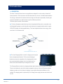
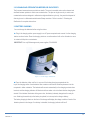
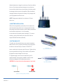
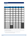
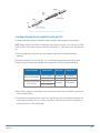
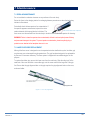
BIOLASE, Inc.
4 Cromwell
Irvine, CA 92618 USA
949.361.1200
888.424.6527
biolase.com
MT Promedt Consulting GmbH
Altenhofstrasse 80
D-66386 St. Ingbert/Germany
+49 6894 581020
mt-procons.com
About BIOLASE
Founded in 1986, BIOLASE, Inc. specializes in lasers for medicine
and dentistry that feature proprietary and patented technologies for
minimally invasive surgeries, reducing pain and improving clinical
results.
Only BIOLASE combines the leading laser technology – continuously
improved through ongoing clinical R&D and engineering – with
unmatched training, practice integration support and service.
BIOLASE leads the global dental laser market with over 21,000 lasers in
use today and the most complete family of dental lasers – from diode
lasers to the most advanced all-tissue laser, the WaterLase iPlus™.
™
User Manual
Made in the USA
©2014 BIOLASE, Inc. All rights reserved.
™
iLase_UserManual_Cover_5400230_Rev_G.indd 1
iLase™ User Manual P/N 5400230 Rev. G (02/2014)
iLase™ User Manual P/N 5400230 Rev. H
2/11/2014 9:52:08 AM
Copyright ©2014
BIOLASE, Inc.
All Rights Reserved.
iLasesoftware copyright ©2010
BIOLASE, Inc.
Biolase, the Biolase logo, iLase, are either trademarks
or registered trademarks of BIOLASE, Inc. Other
trademarks are property of their registered owners.
BIOLASE, Inc.
www.biolase.com
USA
4 Cromwell
Irvine, CA 92618
Telephone: (888) 424-6527
Telephone: (949) 361-1200
Fax: (949) 273-6687
Service: (800) 321-6717
TABLE OF CONTENTS
1 Introduction
2
1.1 Description
2
1.2 Indications for Use
3
1.3 Contraindications
4
2 Precautions and Warnings
5
2.1 Clinical
5
2.2 Laser Safety
6
2.3 Electrical Safety
6
2.4 Fire Safety
6
2.5 Cleaning and Sterilization
2.6 Personal Protective
Equipment
6
3 Installation
5 Clinical
5.1 Presets
6 Cleaning and Sterilization
6.1 Cleaning and Disinfection
6.2 Steam Sterilization of the
Handpiece Cover and Tips
6.3 Disposal- Tips, Batteries,
Device and Parts
7 Maintenance
19
19
20
21
22
22
7
8
8 Troubleshooting and Repairs
24
8
9
3.4 Battery Installation
10
3.5 Attaching a Tip
10
9
8.1 Troubleshooting
8.2 Warning and Error
Messages
8.3 Repairs
9 Laser Calibration
9.1 Laser Calibration
5400230 Rev. H
17
7.1 Regular Maintenance
7.2 iLase Cover Grip
Replacement
7.3 System Configuration
3.1 Unpacking
3.2 Cleaning and Sterilization
Before Use on Patients
3.3 Battery Charging
4 Operating Instructions
4.1 Personal Protective
Equipment
4.2 Preparation for Use
17
22
23
24
24
25
26
26
11
11
10 Specifications
27
11 Labels
28
11
4.3 Starting the iLase
4.4 Initial Selection of a
Procedure
4.5 System Modes
11
12
11.1 Labels
28
12
11.2 Location of Labels
28
4.6 Firing the Laser
13
4.7 Tip Initiation Instructions
14
4.8 Main Screen
4.9 Selecting a Different
Procedure
4.10 Selecting a Pulse Mode
14
4.11 Adjusting Laser Power
16
15
15
1
1 Introduction
1.1 DESCRIPTION
The iLase™ dental soft tissue laser is a surgical device designed for a wide variety of dental soft
tissue procedures. The iLase uses a solid state laser diode as a source of invisible infrared radiation.
The energy is delivered to the treatment site via a single-use fiber optic tip assembly. Several types
of tips are available for use with the iLase to perform different procedures.
The iLase system consists of two elements:
► The iLase Handpiece contains the laser diode, the replaceable fiber optic tip, removable cover
with integrated finger grip, a main body with control electronics, integrated selector·switch, organic
LED (OLED) display, and rechargeable battery. The iLase Handpiece delivers laser energy, under
user control, to the treatment site.
Figure 1·1:
iLase handpiece and fiber optic tip'
► The iLase Charging Station is used for charging and storing the
iLase and replacement batteries. The iLase and discharged
batteries are placed in receptacles in the charging station where
they are automatically recharged. Up to four batteries with or
without main bodies attached may be charged at one time.
The Charging Station contains four charging indicator lights located on the front panel of the charger.
There is one indicator for each of the battery receptacles at the top of the unit. When the indicator
displays an amber color, the battery is charging. A green light indicates that the Battery is fully
charged. The charging station is powered by a low voltage power supply that connects at the rear of
the unit.
5400230 Rev. H
2
1.2 INDICATIONS FOR USE
Dental Soft Tissue Indications: Incision, excision, vaporization, ablation and coagulation of oral soft
tissues including marginal and inter-dental gingival and epithelial lining of free gingiva and the
following specific indications:
► Excisional and incisional biopsies
► Leukoplakia
► Exposure of unerupted teeth
► Operculectomy
► Fibroma removal
► Oral papillectomies
► Frenectomy
► Pulpotomy
► Frenotomy
► Pulpotomy as an adjunct to
► Gingival troughing for crown impressions
root canal therapy
► Gingivectomy
► Reduction of gingival hypertrophy
► Gingivoplasty
► Soft tissue crown lengthening
► Gingival incision and excision
► Treatment of canker sores,herpetic and
► Hemostasis and coagulation
aphthous ulcers of the oral mucosa.
► Implant recovery
► Vestibuloplasty
► Incision and drainage of abscess
► Tissue retraction for impression
Laser periodontal procedures, including:
► Laser soft tissue curettage
► Laser removal of diseased, infected, inflamed and necrosed soft tissue within the
periodontal pocket
► Sulcular debridement (removal of diseased, infected, inflamed and necrosed soft tissue in the
periodontal pocket to improve clinical indices including gingival index, gingival bleeding Index,
probing depth, attachment loss, and tooth mobility).
5400230 Rev. H
3
1.3 CONTRAINDICATIONS
All clinical procedures performed with the iLase must be subjected to the same clinical judgment and
care as with traditional techniques. Patient risk must always be considered and fully understood
before clinical treatment. The clinician must completely understand the patient's medical history prior
to treatment. Exercise caution for general medical conditions that might contraindicate a local
procedure. Such conditions may include allergy to local or topical anesthetics, heart disease, lung
disease, bleeding disorders, and immune system deficiency, or any medical conditions or
medications that may contraindicate use of certain light/laser type sources associated with this
device. Medical clearance from patient's physician is advisable when doubt exists regarding
treatment.
5400230 Rev. H
4
2 Precautions and Warnings
2.1 CLINICAL
PRESCRIPTION REQUIRED: Federal law restricts this device to sale by or on the order of a dentist or
physician or licensed practitioner.
TRAINING REQUIRED: Only licensed professionals who have reviewed and understood this
User Manual should use this device. Additional training from a Biolase Authorized Representative is
strongly recommended.
CLINICAL USE: Use your clinical judgment to determine all aspects of treatment including, but not
limited to, the laser treatment protocol, technique, power settings, pulse duration and pulse interval
settings, mode of operation as well as the tip type and other procedural requirements. Always start
treatment at the lowest power setting for that specific indication and increase as required. Closely
observe and monitor clinical effects and use your judgment to determine clinical parameters and
approach for the treatment. Make appropriate power and settings adjustments to compensate for
varying tissue compositions, density and thickness. Cutting with the iLase is a thermal process and
any transfer or accumulation of heat into adjacent structures may result in a burn and tissue
damage. Always start treatment at the lowest power setting for that specific indication and increase
as required. Be aware of the underlying and adjacent structures such as nerves and blood vessels
when cutting with this device. Do not direct laser energy towards hard tissues such as tooth or bone
or any metallic restorations. Do not direct laser energy towards metallic restorations, cements or
other dental materials. Exercise extreme caution when using this laser inside the pocket, 3rd molar
sockets, channels and other openings where visibility is limited.
ANESTHESIA: When treating soft tissue, anesthesia may not be necessary; patients should be
closely monitored for signs of pain or discomfort at all times. If such signs are present, adjust
settings, apply anesthesia, or cease treatment if required.
INEFFECTIVE REMOVAL OF TISSUE: Ineffective removal of tissue may be caused by improper tip
initiation (see Section 4.7) or reduction in the power output. Check with a Biolase service
representative to make sure that the iLase is functioning properly.
TIP BREAKAGE: Use a bite block to prevent accidental biting and breakage of the tip; use highspeed suction to prevent patient inadvertently swallowing a broken tip and choking.
iLASE WINDOW: Check and clean the protective window of the fiber optic shaft with a cotton swab
moistened with isopropyl alcohol. CAUTION: Failure to check and clean the window will lead to reduced
optical power efficiency and permanent damage to the system (refer to Section 7 for maintenance
information).
5400230 Rev. H
5
2.2 LASER SAFETY
DANGER
Do not look directly into the beam or at specular reflections. Never direct
or point the beam at anyone’s eyes.
WARNING
Do not use this device if you suspect it is functioning improperly or other
than described herein.
WARNING
No modification of this equipment is allowed.
CAUTION
All persons present in the operatory must wear protective laser
eyewear for the laser wavelength of 940nm.
CAUTION
Do not aim the laser at metallic or reflective surfaces. such as surgical
instruments or dental mirrors. Laser beam reflections from these
surfaces create a potential hazard.
CAUTION
Use of controls or adjustments or performance of procedures other than
those specified herein may result in hazardous radiation exposure.
CAUTION
Instrument should be installed and operated according to CAN/CSAZ386-08: Laser safety in health care facilities.
2.3 ELECTRICAL SAFETY
CAUTION
Do not look directly into the beam or at specular reflections. Never direct
or point the beam at anyone’s eyes.
CAUTION
Plug the power supply into a grounded receptacle only. Connection to
an ungrounded receptable may create hazardous conditions.
2.4 FIRE SAFETY
DANGER
Do not operate this device in the presence of explosive or flammable
materials. Flammable anesthetics or oxidizing gases such as nitrous
oxide (N2O) and oxygen (O2) should be avoided. Solvents of adhesives
and flammable solutions used for cleaning and disinfecting should be
allowed to evaporate before laser is used. Attention should also be
drawn to the danger of ignition of endogenous gases.
2.5 CLEANING AND STERILIZATION
WARNING
5400230 Rev. H
The single-use tips are supplied non-sterile and must be sterilized
before use. The iLase Cover is another component that requires
sterilization. Refer to Chapter 6 “Cleaning and Sterilization” for
instructions on sterilizing tips and the iLase cover.
6
2.6 PERSONAL PROTECTIVE EQUIPMENT
Doctor, patient, assistant and all others inside the operatory must wear
PROTECTIVE appropriate laser eyewear protection for the laser wavelength of 940nm.
EYEWEAR
Periodically inspect laser eyewear for pitting and cracking. For
REQUIRED
replacement or additional protective laser eyewear, please contact
Biolase or your authorized dealer.
LASER
PLUME
5400230 Rev. H
Special care must be taken to prevent infection from the laser plume
generated by vaporization of virally or bacterially infected tissue. Use
high speed suction and clinical masks for protection at all times during
the laser procedure.
7
3 Installation
3.1 UNPACKING
Carefully unpack the shipping container and inspect the contents. If any parts are damaged or
missing, do not use the iLase and contact your Biolase representative immediately.
Inside the shipping container you will find the following items:
Description
Model
7400040-01
Charging Station
1
Power Supply – Charging Station
1
iLase Main Body
1
iLase Cover
1
Single-Use Tips
1 Kit
iLase Cover Grips
1 Pkg
Tip Initiation Blocks
1 Pkg
iLase Rechargeable Battery
2
Laser Safety Signs
1
Laser Safety Glasses (Clinician)
2
Laser Safety Glasses (Patient)
1
iLase Cleaning Kit
1
User Manual
1
Retain the shipping container and store it in a cool dry place. Use this container if it becomes
necessary to ship the iLase to Biolase or a Biolase Authorized Service Center.
5400230 Rev. H
8
3.2 CLEANING AND STERILIZATION BEFORE USE ON PATIENTS
The iLase and accessories are provided non-sterile. The cover is reusable and must be cleaned and
sterilized between patients to avoid cross-contamination. The tips are single-use only to avoid crosscontamination and are designed to withstand a single sterilization cycle only; they must be disposed of
after single use in a biohazard medical waste Sharps container. Refer to section 6 “Cleaning and
Sterilization for complete instructions.
3.3 BATTERY CHARGING
You must charge the batteries before using the device.
►Plug in the charging station power supply to an AC power receptacle and connect it to the charging
station as shown below. Place the charging station on a surface where it will not be disturbed or come
in contact with liquids or contaminants.
IMPORTANT: Use only Biolase approved power supplies, P/N 6400422
Figure 3·1: Power Supply Attachment
►Place the batteries, either end first, in any one of the battery charging receptacles at the
top of the charging station. iLase batteries have contacts on both ends and allow placement into the
receptacle in either orientation. The batteries will connect automatically to the charging contacts when
inserted, and the charging indicator will illuminate with an amber color to indicate that the charging has
started. If the indicator illuminates with a green color, the battery is already charged and is ready for
use. Attaching the main body to the battery is optional, but not required to charge a battery.
The battery charging indicator on the front of the charger will display the charge condition of each of the
batteries placed in the charger. If no battery is installed, the charging indicator will be off.
5400230 Rev. H
9
Allow the batteries to charge for a minimum of two hours before
first use. If the battery has been charging for more than two
hours and the indicator has not turned green, the battery might
be damaged and may need to be replaced. When the battery
charging indicator turns green, the battery is fully charged and
you may prepare the device for use.
NOTE: Charge spare batteries for a minimum of 2 hours
before use.
3.4 BATTERY INSTALLATION
Slide a fully charged battery assembly into the socket at the
end of the main body of the iLase. A magnet inside the main
Figure 3-2: Charging Indicat ors
body will grip and hold the battery in place. (Battery assemblies
have contacts on both ends; it is not necessary
to orient the end of the battery when installing it). To remove
a battery, gently pull the battery from the socket until the
magnet releases the battery assembly.
3.5 ATTACHING A TIP
To install a tip, slide a sterile iLase cover onto the handpiece.
Make sure the cover is properly oriented and fits snug against
the button on the main body as shown in FIGURE 3-3.
Insert a sterile tip into the open end of the cover. Tighten the tip
Figure 3-3:
iLase Cover Attachment
by turning clockwise until snug. Once installed, verify that the
tip appears to extend straight from the cover.
If it appears angled, remove and re-install the tip until it
appears straight. Once properly installed, bend the metal
cannula as appropriate for the planned procedure.
CAUTION: Do not bend the tip at a sharp angle as it may break.
Correct Bend
Figure 3 - 4 :
Tip properly installed
Incorrect Bend
Figure 3 -5: Bending the tip cannula
5400230 Rev. H
10
4 Operating Instructions
4.1 PERSONAL PROTECTIVE EQUIPMENT
Doctor, patient, assistant and all others inside the operatory must wear
PROTECTIVE appropriate laser eyewear protection for the laser wavelength of 940nm.
EYEWEAR
Periodically inspect laser eyewear for pitting and cracking. For
REQUIRED
replacement or additional protective laser eyewear, please contact
Biolase or your authorized dealer.
LASER
PLUME
Special care must be taken to prevent infection from the laser plume
generated by vaporization of virally or bacterially infected tissue. Use
high speed suction and clinical masks for protection at all times during
the laser procedure.
4.2 PREPARATION FOR USE
Before using the iLase, make sure the following conditions have been met:
►The iLase charging station power supply is plugged into working AC power receptacle, and at least
one battery is connected to the charging station and charged for at least 2 hours.
►The iLase cover has been sterilized using the sterilization instructions noted in Chapter 6 “Cleaning
and Sterilization.”
►The tips that you plan to use have been sterilized using the sterilization instructions noted in
Chapter 6 “Cleaning and Sterilization.”
►The iLase main body and battery have been disinfected by following the cleaning and disinfecting
instructions noted in Chapter 6 “Cleaning and Sterilization.”
►The iLase has been assembled, including the cover and a fully charged battery assembly.
►A tip appropriate for the planned procedure has been installed in the iLase cover.
4.3 STARTING THE ILASE
Turn on the iLase by installing the battery.
NOTE: To avoid Error message, do not hold the handpiece over the rubber finger grip area at any time in
STANDBY mode. If an error message occurs, simply remove your fingers from the rubber grip and wait until
message clears.
The iLase Welcome Screen is displayed.
Figure 4 -1: Welcome Screen .
5400230 Rev. H
11
Safety operation of laser electronic devices requires prevention of the unauthorized use of
the devices. An electronic key is implemented in the iLase for that purpose. When PLEASE ENTER
KEY appears, there is a progression bar shown for 3 seconds. Triple click the selector switch (rapidly
press three times) to advance to the next screen, Procedures Menu. If the key is not entered, the
system remains on the Welcome screen. To get back to the PLEASE ENTER KEY screen, press the
selector switch once.
Figure 4 -2: l(ey Enter Screen .
4.4 INITIAL SELECTION OF A PROCEDURE
The SELECT PROCEDURE screen will appear once the key is properly entered. Eleven preset
procedures are available; to select a procedure, scroll up or clown using the Selector Switch and press
the switch in on the desired procedure (refer to section 5.1 for a listing of procedure presets).
When you have selected a procedure by pressing the selector switch, the Tip Initiation screen will
appear with the preset values for that operation: 1.4 W, continuous or CW mode.
After two seconds, the system will enter Ready mode and the laser will be ready for firing by pressing
on the rubber grip to initiate the tip. After completing the initiation of the tip, press down the selector
switch to start the procedure using the selected presets.
4.5 SYSTEM MODES
STANDBY MODE: For all operations leading up to the firing of the laser, the system has remained in
STANDBY Mode (as noted by the amber LED in the iLase display). In STANDBY Mode, the user has
the ability to select a new procedure, modify settings for the procedure, and make any other changes
necessary. In this mode, the laser is disabled from accidental firing. Actuation of the finger switch will
be indicated by the error symbol E05 (refer to section 8.2 for a full listing of error messages). If the
selector switch is pressed in for longer than 1.5 seconds or if the iLase is inactive for more than three
(3) minutes, it will go into SLEEP mode.
READY MODE: When a procedure is selected or when you have made any needed adjustments and
are ready to perform a procedure, place the system into READY mode by pressing down the selector
switch. When the iLase is in READY mode, the LED will be green. Only in this mode is the red aiming
beam activated and the laser can be fired. While in READY mode, you may adjust the power only. In
order to save modified settings to a pre-set procedure, press in and hold the selector switch for
5400230 Rev. H
12
1.5 seconds. SAVED will appear on the screen indicating that your modifications are saved under the
current procedure name. You must ensure that all safety precautions have been followed prior to
entering READY mode. (See Section 2 “Precautions and Warnings”). The system will return to
STANDBY mode when it is inactive for more than three (3) minutes.
SLEEP MODE: The system is placed in a low power state to conserve battery power. All LED's and
the Display panel are turned off in this mode. The system will enter STANDBY mode with the last
settings used when the Selector Switch or Finger Switch is pressed.
4.6 FIRING THE LASER
EMERGENCY
STOP
To immediately stop laser emission, pull the battery from the iLase main
body.
NOTE Most procedures require tip initiation before using the iLase. For those procedures that require tip
initiation, you must complete the tip initiation steps before using the iLase in a procedure on a patient. If tip
initiation is not required or has already been initiated, press the selector switch to bypass this operation.
1 Make sure the iLase has a tip installed that is appropriate for the planned procedure.
2 Make sure that all personnel in the operatory are wearing laser protective eyewear.
3 After the user enters READY mode, the LED on the iLase will be green. The red aiming beam will
also appear at this time. The laser is now ready to fire.
4 Prior to firing, verify that the tip is installed correctly into the iLase cover by shining the red
aiming beam onto a bright surface, such as a white table top. If using a tip that requires initiation (not
pre-initiated), make sure the aiming beam image appears as in the example below:
When the tip is straight, the
aiming beam will look like a
circle, outlining the area
where the main laser power
is applied.
When the tip is bent, the
aiming beam will more like a
spot, and the main laser
power (invisible infrared
radiation) will be applied in the
middle of the spot.
Fi g ur e 4 -3: Ai ming beam patt ern.
WARNING: When the aiming beam is not present or has a significantly different shape, change the tip
and inspect / clean the protective window until the image appears as shown above.
5 Use the aiming beam to position the tip over the target treatment area. Place the laser tip on the
treatment area and press the finger switch (or gently squeeze the finger grip) on the iLase to fire
the laser. Actuation will occur when the finger grip is pressed over any one of the six ridges anywhere
along the whole length of the switch.
5400230 Rev. H
13
6 The iLase will immediately emit a "beep" tone, then after a 0.3 second delay, the laser will
fire. Laser firing is indicated by a blinking green LED and pulsing beep sound.
7 Release the finger switch to stop laser emission.
4.7 TIP INITIATION INSTRUCTIONS
VERIFYING THE TIP
Prior to initiating the tip, verify that it is installed correctly into the iLase cover (see previous section).
The Tip Initiation Aid screen appears as you enter Ready Mode [1.4W / CW]. You will need to have
the Tip Initiation Block handy to perform this step.
Figure 4 -4: Tip In itiation Screen.
Touch the tip to the surface of the tip initiation block, without firing. Fire the laser by gently squeezing
the finger grip, allowing the tip to sink into the block. Pull the tip out when the metal cannula touches
the block, still firing until just before the tip is out of the block. Fire the laser into the air once. You will
see a white flash or a glowing tip. A glowing tip indicates that the tip is ready for use. During a
procedure, there is a chance the tip can lose its initiation; repeat the tip initiation procedure, if
necessary.
When you have finished the tip initiation, you are ready to begin the procedure. Press the Selector
Switch to move to the Main Screen while keeping the system in Ready Mode.
4.8 MAIN SCREEN
The Main screen shows the current settings of the iLase.
► The top left corner of the screen displays the battery power level.
► The top center of the screen displays the name of the currently selected procedure.
► The Pulse Mode icon (lower left) indicates the currently selected pulse mode.
► The Power icon (lower center) indicates the current laser power setting (average output power).
5400230 Rev. H
14
While in READY mode, you may adjust the power level at any time during the procedure by toggling
up (+) or down (-) the selector switch; however, the pulse mode may not be changed in READY mode.
You must return to STANDBY to change the pulse mode.
When your procedure is complete, press the selector switch on the iLase to enter STANDBY
mode. The LED on the iLase will turn an amber color. The system is now in STANDBY mode. You
can modify and save new settings for the Procedure by changing power values and pressing and
holding the selector switch for approximately 1.5 seconds while in READY mode.
NOTE: Pressing the finger switch for 60 seconds while firing will cause the laser to stop firing. To
continue firing, release the finger switch and then press again.
4.9 SELECTING A DIFFERENT PROCEDURE
While in Standby mode in the Main Screen, highlight the Procedure Name using the up (+) motion of
the selector switch, and make your selection by pressing the finger switch. The procedure screen will
be displayed.
Scroll up (+) or down (-) to select a new procedure, or select your own Custom setting.
After a new procedure is selected, the system will go to the Tip Initiation and Main screens in READY
mode. Switch to STANDBY mode If you need to continue modifying the preset.
4.10 SELECTING A PULSE MODE
While in Standby mode in the Main Screen, highlight and select the pulse mode icon to access the
Pulse Mode menu; one of three available pulse modes can be chosen from that menu by using the
selector switch.
Figure 4 -7: Pulse Mode Selection Screen.
For a pulse that is 0.1ms on, followed by 0.2ms off, select CP1.
For a pulse mode that is 1.0ms on, followed by 1.0ms off, select CP2.
For continuous wave ouptut (not pulsed), select CW.
Return to the main screen by selecting one of the available pulse modes.
5400230 Rev. H
15
4.11 ADJUSTING LASER POWER
If you wish to change the power setting, highlight and select the power icon in the Main Screen in
STANDBY mode to display the Power Setting screen. The figure below does not show a power
setting, but rather has "[X.X] W" to indicate the numeric format of the average power setting.
The Power Setting screen displays the current laser output power setting in both Peak and Average
Power values and allows you to adjust the power up (+) or down (-).
Using the selector switch, scroll up to the " + " sign to increase the power; scroll down to the " - " sign
to decrease the power. The power setting increases or decreases by one increment each time the
selector switch is scrolled. When the power setting has reached its upper or lower limit, the value will
remain at the limit.
Fi gure 4 -8: Power Setti ng Screen.
Press the selector switch to return to the main screen. You can also access the Settings Menu from
this screen. For further details of the Settings Menu refer to the Maintenance section of this manual.
5400230 Rev. H
16
5 Clinical
5.1 PRESETS
iLase has 11 pre-programmed settings, plus 2 open slots to allow the user to set and store
customized settings.
Preset Name
Tip
●
Initiation
Peak
Power
Average
Power
Pulse
Length
CP1
(0-10ms)
Pulse
Interval
1
Gingivectomy
Yes
3.00W
1.00W
2
Troughing
Yes
2.00W
1.00W
CP2
(1.00ms)
1.00ms
3
Excision
Yes
1.80W
0.90W
CP2
(1.00ms)
1.00ms
4
Frenectomy
Yes
2.00W
1.00W
CP2
(1.00ms)
1.00ms
5
Implant Recovery
Yes
2.40W
1.20W
CP2
(1.00ms)
1.00ms
6
Crown Lengthening
Yes
1.80W
0.90W
CP2
(1.00ms)
1.00ms
7
Perio Pockets
Yes
1.60W
0.80W
CP2
(1.00ms)
1.00ms
8
Exposure of Unerupted
Teeth
Yes
1.80W
0.90W
CP2
(1.00ms)
1.00ms
9
Aphthous Ulcer
No
0.70W
0.70W
CW
10
Hemostasis
No
0.50W
0.50W
CW
11
Endo (*)
0.10W
0.10W
CW
12
Custom 1 (*)
0.10W
0.10W
CW
13
Custom 2 (*)
0.10W
0.10W
CW
●
0.20ms
Not required for pre-initiated tips
(*) Minimum defaults provided for user setting of Endodontic Procedures such as Pulpotomy and Pulpotomy
as an adjunct to root canal therapy
► The first 8 procedures listed are performed in contact mode. Aphthous Ulcer and
Hemostasis require a defocused mode of application.
5400230 Rev. H
17
► 300µm tips are recommended for removing less fibrous tissue types. 400µm tips
are recommended for removing fibrous tissue and inside the pocket.
► All of the procedures listed require tip initiation except for Hemostasis and Aphthous Ulcer.
► For information on how to initiate the tips that are not pre-initiated, please refer to the Tip
Initiation Instructions provided in Section 4.
5400230 Rev. H
18
6 Cleaning and Sterilization
6.1 CLEANING AND DISINFECTION
CAUTION: During use the internal components of the iLase under the cover may become hot to the touch.
Allow the iLase to cool for a few minutes before removing the cover for cleaning and sterilization.
The iLase must be cleaned prior to use on each patient. Cleaning must be performed within a
maximum of one (1) hour after the procedure, and prior to sterilization. Manual cleaning is
recommended.
Prepare a cleaning solution per the manufacturer’s instructions. Use a commercially available
surgical instrument detergent/enzymatic cleaning solution with a pH of 7.0, such as Enzol®, or a
similar enzymatic presoak and cleaner. Follow the instructions for disposal of used solution.
To disinfect the iLase main body and battery, perform the following steps in the indicated order:
1 Place the iLase in STANDBY mode.
2 Wear protective gloves and eyewear when handling the contaminated main body and battery.
3 Remove the used tip from the cover (if present) and dispose of in a biohazard medical waste
Sharps container.
4 Remove the battery from the main body and set it aside.
5 Pull the iLase cover forward and slide it off the body of the main body.
6 To disinfect the main body, wipe with an appropriate disinfecting solution,such as Cavidice® or a
similar quaternary ammonium compound product (containing 20% alcohol or less) and follow the
manufacturer’s instructions.
CLEANING THE COVER
1 Rinse the cover under lukewarm water (22 - 43º C) for a minimum of 10 seconds to remove gross soil.
2 Soak a piece of gauze in the cleaning solution and wrap the handpiece cover. Leave it
wrapped for a minimum of 10 minutes. Unwrap, and using a soft-bristled brush dipped in the
cleaning solution, gently brush the cover for at least 15 seconds.
3 Rinse the cover under lukewarm running tap water (22 - 43º C) for a minimum of 10 seconds and
dry with a lint-free cloth.
4 Visually inspect the cover for any residual soil. If present, repeat steps 1 through 3 until residual
soil is removed.
5400230 Rev. H
19
Figure 6–1: Disassembly for Disinfection, Cleaning, and Sterilization
6.2 STEAM STERILIZATION OF HANDPIECE COVER AND TIPS
The steam sterilization process is intended to destroy infectious microorganisms and pathogens.
NOTE: Always perform the procedure immediately after cleaning and prior to use and only use FDAcleared (USA) or CE-marked (Europe) sterilization accessories, i.e., sterilization pouch and autoclave
tray.
1 Place the handpiece cover and/or tips inside separate single-wrap, self-sealed sterilization
pouch(es).
2 Place the pouch(es) on an autoclave tray. Do not stack other instruments on top of the pouches.
3 Place the tray into the autoclave chamber and set appropriate cycle as recommended below:
Type of Sterilizer
Gravity Displacement
Dynamic-Air-Removal
(Pre-Vacuum)
Temperature
Min Time
Drying Time
121°C ( 250°F)
20 minutes
0 minutes
132°C (270°F)
15 minutes
15-30 minutes
4 minutes
20-30 minutes
132°C (270°F)
134°C (EU only)
4 When cycle is complete, the handpiece cover and tips must remain in the sterilization pouches until
used to maintain sterility.
5 To assemble the components when ready to use, slide the cover over the handpiece main body and
push it toward the window until you it ‘clicks’ into position. Install the tip and connect the battery as
detailed in Section 3 of this User Manual.
5400230 Rev. H
20
6.3 DISPOSAL
TIPS
Tips are designed to be used one time only and must be sterilized prior to each use. Proper tip
disposal in a biohazard medical waste Sharps container is required. Do not reprocess tips.
BATTERIES
Lithium ion batteries contain toxic materials and should not be disposed of in landfills or incinerators.
Dispose of depleted batteries as directed by your local solid waste handling regulations. If you have
questions or need advice about safe disposal of used batteries, contact Biolase or your Biolase
Authorized Service Representative.
DEVICE AND PARTS
The iLase is a medical device subject to regulations governing its disposal. Contact Biolase or your
Biolase Authorized Service Representative for instructions on returning the device to Biolase for
disposal. Do not dispose of an iLase or its parts in landfills or incinerators.
5400230 Rev. H
21
7 Maintenance
7.1 REGULAR MAINTENANCE
Do not use bleach or abrasive cleansers on any surfaces of the main body.
Return the iLase to the charging station for recharging between procedures or when the low-battery
indicator is illuminated.
Periodically check the laser aperture for contamination. If
the aperture appears contaminated, wipe with a cotton
Check and Clean Laser Aperture
swab moistened with isopropyl alcohol until clean. The
iLase cover must be removed from the main body to be able to access the laser aperture for cleaning.
WARNING: Failure to clean the aperture when contaminated, will lead to reduced optical power efficiency
and permanent damage to the system. To prevent aperture contamination, please keep the tip plug or
protective cover attached to the handpiece when not in use.
7.2 iLASE COVER GRIP REPLACEMENT
Although the iLase cover is designed to survive repeated autoclave sterilization cycles, its rubber grip
may become worn or damaged through repeated use. The grip has been designed to be replaceable
by the user if it becomes necessary. The iLase system is shipped with two additional grips for this
purpose.
To replace the rubber grip, remove the iLase cover from the main body. Slide the old grip off of the
small end of the cover and slide a new rubber grip onto the same end with the large end of the grip
first. Ensure that the grip alignment tabs on the grip snap into the grip alignment holes on the cover,
as shown below:
Grip Alignment Tabs
Figure 7-1: Cover Grip Alignment
5400230 Rev. H
22
7.3 SYSTEM CONFIGURATION
The Settings Menu screen allows you to adjust the settings of the user interface. The Settings Menu
is entered by pressing and holding down the selector switch for approximately 1.5 seconds when in
the Main Screen while in Standby mode.
Figure 7-2: Settings Screen (Aiming beam currently s hown)
The following screens are available in the Settings Menu:
► Aiming Beam: To modify the aiming beam brightness.
► Restore All: To restore all procedures and preferences to their default settings.
► Language: To select from the available languages.
► Exit: To exit the Settings Menu
Aiming Beam allows you to adjust the brightness of the aiming beam. To change the brightness,
select the Increase or Decrease arrow icons. The aiming beam has 3 brightness settings: level 1 is
the lowest setting and level 3 is the highest at 1mW output. Level 2 is the default setting.
The Restore All button will reset the aiming beam brightness. preset values, and language selection
to their default settings.
The Language selection will enable selection from up to 10 different languages.
5400230 Rev. H
● English
● French
● German
● Russian
● Italian
● Portuguese
● Spanish
● Chinese (Mandarin)
● Korean
● Japanese
23
8 Troubleshooting and Repairs
8.1 TROUBLESHOOTING
The following tables list warning and error messages which indicate conditions that can usually be
remedied by the user. If the recommended corrective action does not solve the problem and the
message persists, restart the iLase by removing the battery, waiting 5 seconds. and then re-installing
the battery. If the error message reappears after restarting the iLase, the system cannot be used until
the cause of the error has been remedied. Call Biolase Service at (800) 321-6717 or your Biolase
Authorized Service Representative.
8.2 WARNING AND ERROR MESSAGES
The Warning and Error screens display codes and recommended corrective actions. If a Warning or
Error message is displayed, perform the indicated corrective action.
Figure 8-1: Fi nger Switch Actuated.
Error/Warning Code
Error/Warning Description
Action
E01 Temperature Sensor open
(check at start up)
Call Service
E02 Temperature Sensor short
(check at start up)
Call Service
E03 Laser system overheated
Wait to cool off
E04 Laser current is outside of
allowed range
Call Service
E05 Finger switch actuated in
STANDBY mode
Release Finger Switch
E06 Up/down/select switch
stuck
Call Service
E07 Check Sum Error
(memory integrity)
Call Service
W01 Warning temperature
W02 Warning low battery level
5400230 Rev. H
Wait to cool off
Battery replacement may be
necessary
24
8.3 REPAIRS
There are no user-serviceable parts in the iLase. Do not open any part of the device or attempt to
make repairs. Doing so may expose the user to unsafe voltages, high temperatures, or laser energy
and may void the product's limited warranty.
To obtain repair service for your iLase, call Biolase Service at 1-800-321-6717 or your Biolase
Authorized Service Representative.
5400230 Rev. H
25
9 Laser Calibration
9.1 LASER CALIBRATION
Biolase recommends that a laser calibration be performed every 12 months to ensure that the laser
output power corresponds accurately to the displayed power. Annual calibrations can be performed at
a Biolase Authorized Service Center.
Call Biolase Service at 1-800-321-6717 or contact your Biolase Authorized Service Representative to
schedule an appointment.
5400230 Rev. H
26
10 Specifications
Dimensions
Charging Station (W X D X H)
iLase Handpiece with surgical tip and battery
attached (Length X Diameter)
Power Supply (W X D X H)
4.7” X 4.0” X 2.8” / 11.9 cm X 10.2 cm X 7.1 cm
8.1” X 0.75” / 20.5 cm X 1.90 cm
1.77” X 2.36” X 2.26” / 4.5 cm X 6.0 cm X 6.0 cm
Weight
iLase Complete System
1.89 lbs / 0.86 kg
iLase Charging Station
0.87 lbs / 0.34 kg
iLase with Battery attached
iLase Charging Station PowerSupply and cord/plug
set
Electrical
0.22 lbs / 0.10 kg
0.62 lbs / 0.28 kg
Voltage (to power supply)
90 – 230 VAC
Amperage (max)
0.8A
Frequency
50 – 60 Hz
Electrostatic Discharge Immunity
Up to 10 KV (per IEC 60601)
Battery
Lithium ion 3.7 V 800 mAh
Recharge Time (fully discharged)
Safety
2 hours
Discharge over current sensor and resettable circuit
breaker
Laser
Laser Class
IV (4)
Wavelength
940 nm ± 10nm
Output Power
3.0 W Max CW / 5.0 W Peak Power (Pulse Mode)
Power Accuracy
± 20%
Pulse Duration
Continuous | 0.1 ms | 1 ms
Pulse Interval
-------------- | 0.2 ms | 1 ms
Aiming Beam
Laser diode, max 1 mW, 625-670nm, Class 1
N.O.H.D.
2.61 meters
Environmental
5400230 Rev. H
Temperature - Operating
68° – 77° F (20° – 25° C)
Temperature - Storage
59° – 90° F (15° – 35° C)
Humidity - Operating
15 – 95 % non-condensing
Humidity - Storage
10 – 70 % non-condensing
Altitude - Operating
maximum 10,000 ft (3048 m)
Altitude - Storage
maximum 12,000 ft (3658 m)
27
11 Labels
11.1 LABELS
The iLase is labeled as indicated in the following table. Refer to Figures 11-2 for label locations.
Label
Description
Location
Product ID Label
Charging Station, rear.
Refer to Section 11-2.
Certification Label
Charging Station, underside.
Refer to Section 11-2.
Laser Warning Label
Charging Station, rear.
Refer to Section 11-2.
Laser Aperture
Handpiece near battery end.
Refer to Section 11-2.
11.2 LOCATION OF LABELS
Instruction and warning labels are affixed to the device in the locations shown.
5400230 Rev. H
28
BIOLASE, Inc.
4 Cromwell
Irvine, CA 92618 USA
949.361.1200
888.424.6527
biolase.com
MT Promedt Consulting GmbH
Altenhofstrasse 80
D-66386 St. Ingbert/Germany
+49 6894 581020
mt-procons.com
About BIOLASE
Founded in 1986, BIOLASE, Inc. specializes in lasers for medicine
and dentistry that feature proprietary and patented technologies for
minimally invasive surgeries, reducing pain and improving clinical
results.
Only BIOLASE combines the leading laser technology – continuously
improved through ongoing clinical R&D and engineering – with
unmatched training, practice integration support and service.
BIOLASE leads the global dental laser market with over 21,000 lasers in
use today and the most complete family of dental lasers – from diode
lasers to the most advanced all-tissue laser, the WaterLase iPlus™.
™
User Manual
Made in the USA
©2014 BIOLASE, Inc. All rights reserved.
™
iLase_UserManual_Cover_5400230_Rev_G.indd 1
iLase™ User Manual P/N 5400230 Rev. H
iLase™ User Manual P/N 5400230 Rev. G (02/2014)
2/11/2014 9:52:08 AM