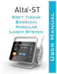
1
Diolase Plus™
A SOFT-TISSUE LASER
User Manual
© 2004 Biolase Technology, Incorporated. All Rights Reserved.
BIOLASE Diolase Plus™ User Manual.
BIOLASE, the BIOLASE logo, Diolase, Diolase Plus™ and the Diolase Plus™ logo are either
registered trademarks or trademarks of BIOLASE Incorporated in the United States and/or other
countries.
BIOLASE Technology, Inc.
981 Calle Amanecer, San Clemente, CA 92673 USA
NoPainDentistry.com · NASDAQ: BLTI
BIOLASE Europe GmbH
Paintweg 10, 92685 Floss, Germany
5000910 Rev. A (06/04)
Contents
Introduction ................................................................................. 5
Section 1
Installation of the Diolase Plus™............................................... 5
Installation Instructions ............................................................................. 5
Facility Requirements................................................................................ 5
Electrical Supply ................................................................................. 5
Environmental Requirements ............................................................. 5
Section 2
Safety with the Diolase Plus™ ................................................... 6
Precautions ............................................................................................... 6
Safety Instructions..................................................................................... 6
Safety Features......................................................................................... 7
Energy Monitor .................................................................................. 7
Circuit Breaker.................................................................................... 7
System Monitor................................................................................... 7
Keyswitch............................................................................................ 7
READY Button ................................................................................... 8
Footswitch .......................................................................................... 8
Emergency Stop ................................................................................. 8
Remote Interlock ................................................................................ 9
Functional Display .............................................................................. 9
Safety Questions....................................................................................... 9
Safety Classification.................................................................................. 9
Section 3
Equipment Description ............................................................. 10
General ................................................................................................... 10
Console ................................................................................................... 10
Control Panel.................................................................................... 11
Unit Features .................................................................................... 12
Accessories ..................................................................................... 12
Delivery System ..................................................................................... 15
Delivery System Assembly .................................................................... 15
Directions for Cleav ing Diolase Plus™ Fiber After Each Procedure .... 16
Section 4
Operating Instructions .............................................................. 19
Unit Setup ............................................................................................... 19
Operation ................................................................................................ 19
Turn On the Diolase Plus™.............................................................. 19
ON/OFF Button................................................................................. 19
READY/STANDBY Buttons .............................................................. 20
LASER FIRING Icon......................................................................... 20
MODE Buttons ................................................................................. 20
POWER Buttons............................................................................... 20
PULSE DURATION Buttons............................................................. 20
PULSE INTERVAL Buttons .............................................................. 20
FUNCTION Key................................................................................ 20
PRESET Buttons .............................................................................. 20
Turn the Unit OFF............................................................................. 21
Section 5
SPECIFICATIONS....................................................................... 22
General .................................................................................................. 22
Electrical.................................................................................................. 22
Laser ....................................................................................................... 22
Other Light Sources .............................................................................. 22
Section 6
CONTRAINDICATIONS, WARNINGS AND PRECAUTIONS ... 23
Contraindications ................................................................................... 23
Warnings and Precautions..................................................................... 23
Section 7
CLINICAL APPLICATIONS ....................................................... 24
Introduction ............................................................................................ 24
Table of Indications for Use ................................................................... 24
Section 8
MAINTENANCE ......................................................................... 25
Annual Maintenance ..............................................................................
Daily Maintenance .................................................................................
Contamination Control Procedure ........................................................
Cleaning ..........................................................................................
High-level Disinfection Instructions for the Fiber Optic Cable .........
Steam Sterilization for Diolase Plus Surgical Handpiece................
Transportation .................................................................................
Storage...................................................................................................
Section 9
25
25
25
25
25
26
26
26
CALIBRATION ........................................................................... 27
Calibrating Power................................................................................... 27
Calibration Schedule:............................................................................. 27
Appendix
A - LABELS................................................................................. 28
B - SIGNS.................................................................................... 31
C - SPARE PARTS AND ACCESSORIES ................................. 33
D - LIMITED WARRANTY........................................................... 34
E - LIMITED LIABILITY............................................................... 34
Diolase Plus™
User Manual
INTRODUCTION
The Diolase Plus™ Dental Soft Tissue Laser is a surgical device at the cutting edge
of technology, designed for a wide variety of oral soft tissue procedures. The Diolase
Plus™ utilizes a solid state diode as a laser energy source, and the energy is
delivered to the operating area by means of a delivery system consisting of flexible
fiber connecting the laser source and the handpiece. The device is activated by
means of a footswitch.
The Diolase Plus™ is intended for use by dentists in oral soft tissue
procedures. The use of this device requires proper clinical and technical training.
This manual provides instructions for professionals that have completed the
appropriate training.
When used and maintained properly, the Diolase Plus™ will prove a valuable
addition to your practice. Please contact your authorized representative if you have
any questions or require assistance.
Section 1: INSTALLATION
Installation Instructions
Upon request, your local authorized representative will unpack and install the
Diolase Plus™.
The Diolase Plus™ system includes the following:
•
Console
•
Delivery System (Handpiece and Fiber Assembly)
•
User Manual
•
3 Safety Goggles
•
Footswitch
•
Power Cord
•
Carbide fiber scriber
•
Micro fiber stripper 400um
•
Laser Radiation Danger Sign
•
Accessory Pouch (includes remote interlock plug, ground clip, key)
Use proper care prior to transporting the unit. Refer to Section 8 in this manual for
instructions. Misalignment of optical components may occur during transportation.
Facility Requirements
Electrical Supply (100-240V)
1.5 - 3A, 50/60Hz
Environmental Requirements
Temperature:
20-25 ºC
Humidity:
15-95% Relative
©2004 Biolase Technology, Inc. All Rights Reserved.
5
Section 2
Safety
Section 2: SAFETY
Precautions
Failure to comply with precautions and warnings described herein may lead to
exposure to dangerous voltage levels or optical radiation sources. Please comply
with all safety instructions and warnings.
CAUTION:
Use of controls or adjustments or performance of
procedures other than those specified herein may result in hazardous
radiation exposure.
DANGER:
Do not use this unit if you suspect it of functioning
improperly or other than described herein.
CAUTION:
This unit has been designed and tested to meet the
requirements of electromagnetic, electrostatic, and radio frequency
interference testing. However, the possibility of electromagnetic or other
interference may still exist.
Safety Instructions
Follow these safety instructions before and during treatments:
•
All operatory entrances must be marked with an appropriate warning sign.
(See Appendix B.1)
•
Do not operate in the presence of explosive or flammable materials.
•
All persons present in the operatory must wear protective eyewear.
CAUTION: Periodically inspect eyewear for pitting and cracking.
Note: For replacement, additional or prescription protective eyewear, please contact
your authorized representative.
•
Do not look directly into the beam or at specular reflections.
•
Never direct or point the beam at anyone's eyes.
•
Remove or cover all highly reflective items in the treatment area.
•
Press STANDBY (Standby button) on the control panel before turning
off unit.
•
Always press STANDBY on the control panel before exchanging
handpieces or removing the fiber optic connector from the unit.
•
Move the circuit breaker (located on rear panel) to OFF (0) position and
remove the key before leaving unit unattended.
DANGER:
Do not open unit housing at anytime. Danger from high
voltage may exist.
NOTE: Please be aware that metal/plastic cannulas may become hot during use.
Avoid contact of cannulas with tissues.
6
5000910 Rev. A (06/04)
Diolase Plus™
User Manual
Safety Features
Energy Monitor
The energy monitor measures and verifies power output. Power deviations of more
than 20% from the selected value will cause the display to show either error
message “DIODE CALIBRATION” or “LASER POWER”.
The unit will not operate until the system is reset by pressing any key on the keypad.
If error messages persist, please contact your authorized service representative.
Circuit Breaker
The circuit breaker serves as a line switch to separate the unit from the main power
supply (0 = OFF, I = ON).
Figure 1: Circuit Breaker
System Monitor
The system monitors the emergency stop switch, remote key, footswitch attachment,
fiber attachment, and output power. An error in any one of these will stop the system,
the text display will indicate the type of error. Operation will not resume until the error
is cleared, and the text once again displays “Biolase Technology.”
Keyswitch
The unit can be switched ON (key in horizontal position) only with the proper key.
The key cannot be removed while in the ON position. Always turn the key off (vertical
position) and remove the key when not in use.
Figure 2: Keyswitch
©2004 Biolase Technology, Inc. All Rights Reserved.
7
Section 2
Safety
READY Button
Once the circuit breaker, keyswitch, and ON/OFF switch are set to the ON position, the
READY button on the keypad must be pressed to enable the footswitch. One beep will
sound to indicate that the system is ready for use.
Footswitch
The Diolase Plus™ will not emit laser energy until the user pressed down on the
footswitch. The variable footswitch works like a rheostat. The amount of energy emitted
from the fiber will be proportional to the amount the footswitch is pressed. The footswitch
may also be selected to function as a switch. (See Section 4: Function Key).
Figure 3: Footswitch (Domestic)
Figure 4: Footswitch (International)
Emergency Stop
Press the red emergency stop button to instantly turn off the unit. Rotate and release
button to RESET. Do not use the emergency stop for normal stops.
Figure 5: Emergency Stop
8
5000910 Rev. A (06/04)
Diolase Plus™
User Manual
Remote Interlock
This feature allows the device to be connected to the remote sensor which will
prevent its operation when triggered (i.e., by opening door). This feature may be
overridden by inserting the remote interlock plug.
Functional Display
The System Text Display and the Light Emitting Diode (LED) indicators on the
control panel show the functional conditions of the system.
Safety Questions
Please direct any safety questions to an authorized representative.
Safety Classification
The following safety classifications are applicable to the device
• Laser Radiation – Class 4
• Type of protections against electrical shock – Class 1
• Degree of protection against electrical shock – Type B Applied Part
• Not protected against water ingress – Ordinary Equipment
• Not suitable for use in presence of flammable anesthetic mixture
• Operation Mode – Continuous Operation
©2004 Biolase Technology, Inc. All Rights Reserved.
9
Section 5
Specifications
Section 3: EQUIPMENT DESCRIPTION
General
The Diolase Plus™ consists of two components:
•
Console
•
Delivery System
Console
The Console Elements are the:
•
Control Panel
•
Unit Features
•
Accessories
Control Panel (See Figure 6)
Item#
10
Item
1
2
3
4
ON/OFF
ACTUAL POWER DISPLAY
LASER FIRING ICON
MAXIMUM POWER DISPLAY
5
POWER (up/down)
6
7
8
9
10
11
12
AIMING BEAM (up/down)
AIMING BEAM INTENSITY
FUNCTION
PULSE DURATION (up/down)
PULSE INTERVAL (up/down)
PRESET LEDs
PRESET
13
MODE
14
15
16
COUNTER RESET
PULSE COUNTER DISPLAY
MODE ICON
17
18
19
20
21
22
23
INTERVAL DISPLAY
PULSE DURATION DISPLAY
SYSTEM STATUS DISPLAY
READY
READY LED
STANDBY
STANDBY LED
5000910 Rev. A (06/04)
Item Description
Turns the unit on and off.
Indicates average power delivered.
Flashes when laser energy is delivered.
Indicates maximum allowable delivered
power.
Allows adjustment of maximum delivered
optical power.
Allows adjustment of aiming beam intensity.
Indicates aiming beam intensity.
Selects user function.
Allows adjustment of pulse length.
Allows adjustment of pulse interval.
Indicates which preset is currently selected.
Allows for selection of system presets.
Holding button saves selected values.
Toggles between continuous, repeat pulse
and single emission modes.
Resets pulse counter to zero.
Indicates total pulses delivered.
Indicates currently selected mode
(continuous, repeat pulse, single)
Indicates interval between pulses.
Indicates length of each pulse.
Indicates system errors or status.
Allows energy delivery.
Indicates unit is in READY mode.
Does not allow energy delivery.
Indicates unit is in STANDBY mode.
Diolase Plus™
User Manual
Figure 6: Control Panel
©2004 Biolase Technology, Inc. All Rights Reserved.
11
Section 5
Specifications
12
Unit Features
• Base
• Delivery System
• Emergency stop
• Fiber Optic Cable
• Fiber spool
• Footswitch connector
• Handle
• Handpiece holder
• Head
• Keyswitch
• Laser aperture
• Main Circuit Breaker
• Male Connector
• Power connector
• Remote Interlock connector
• Ventilation channels
(Figure 10)
(Figure 10)
(Figure 7, 8 and 9)
(Figure 10)
(Figure 9)
(Figure 8)
(Figure 9,10)
(Figure 7 and 9)
(Figure 10)
(Figure 8)
(Figure 9 and 14)
(Figure 8)
(Figure 10)
(Figure 8)
(Figure 13)
(Figures 7 and 8)
Accessories
• Footswitch
• Key
• Laser Safety Glasses
• Power cord
• Remote interlock plug
(Figure 3 and 4)
(Figure 8)
(Not Shown)
(Not Shown)
(Figure 8)
5000910 Rev. A (06/04)
Diolase Plus™
User Manual
Figure 7: Side View
Figure 8: Back View
©2004 Biolase Technology, Inc. All Rights Reserved.
13
Section 5
Specifications
Figure 9: Front View (Domestic Unit)
14
5000910 Rev. A (06/04)
Diolase Plus™
User Manual
Delivery System
NOTE: The fiber optic cable, handpiece, and heads (See Figure 6) are shipped nonsterile.
The Feed through Delivery System consists of:
•
NOTE:
Fiber Optic Assembly (See Figure 10).
The standard fiber optic cable assembly is a 400µm fiber. Other sizes are
available upon request.
•
Handpiece
•
Base
•
Handle
•
Head (30Þ)
•
Accessories: Adapter (To be used with Disposable/Bendable Tip)
•
Diolase Plus™ Handpiece Kit (See Figure 11)
NOTE:
The fiber optic cable, handpiece, and head are reusable accessories that
require cleaning and sterilization before and after each patient treatment.
For instructions on cleaning and sterilization of the fiber optic cable,
handpiece and head, refer to section 8. Fiber optic cable is not autoclavable
unless labeled as "autoclavable."
Diolase Plus™ Surgical Handpiece Assembly
To connect handpiece to fiber optic assembly:
1. Loosen Handpiece Base from Handpiece Handle. (See Figure 10a)
2. Slide fiber through Handpiece Base, Handle and Head.
3. Adjust fiber so it protrudes approximately 2 inches.
4. Strip and cleave fiber. (See Figure 10b)
5. Adjust to desired length. (See Figure 10c)
6. Gently tighten Handpiece Base to secure Handpiece to the Fiber Optic
Assembly. (See Figure 10d)
To disassemble Handpiece from Fiber optic cable (See Figure 10):
1. Loosen Handpiece Base.
2. Slide Handpiece off of fiber optic cable.
To change Handpiece Head (See Figure 10):
1. Disassemble Handpiece from Fiber optic cable.
2. Change Handpiece head by holding handle and rotating head.
NOTE:
For unit set up instructions, refer to Section 4: Operating Instructions.
©2004 Biolase Technology, Inc. All Rights Reserved.
15
Section 5
Specifications
Directions for Cleaving Diolase Plus™ Fiber
The Diolase Plus™ fiber should be cleaved after each procedure.
To cleave the fiber, refer to the following steps:
1. Loosen the proximal end of the handpiece (Fig.10a) by unscrewing the
Handpiece Base.
2. Pull 2-3 inches of fiberoptic cable from the Handpiece Head through the
Handpiece.
3. Select a fiber stripper that corresponds to the fiber diameter size.
4. Insert approximately 1 inch of the fiberoptic cable into the stripper. Squeeze the
stripper handles to get a firm purchase on the fiberoptic cable, while keeping a
firm grip on the fiberoptic cable, pull the stripper away from the handpiece in a
smooth motion to ensure that the jacket is cleanly removed.
5. Use a diamond/carbide cleaver to cut the used end of the fiber. Place the fiber
against a flat surface. Position the edge of the cleaver approximately 1/4 inch
from the end of the fiber, and make a scratch around half the circumference of
the fiber. Make sure that the edge of the cleaver is always perpendicular to the
fiber during scratching.
6. Hold the end of the fiber above the scratch between thumb and forefinger and
pull the end of the fiber away until the end section breaks off. If the fiber end is
removed properly by pulling in the direction perpendicular to the end surface of
the fiber, the fiber should end in a flat surface.
7. Verify the cleave quality by aiming the fiber at a flat surface and observing the
shape of the spot created by the visible aiming beam. If the visible spot is a full
circle, then the power output is optimal. If the circle is distorted then repeat only
the cleaving procedure presented in steps 5 and 6 until you obtain a perfect circle
beam.
8. After the fiber is successfully cleaved, pull the fiber back through the Handpiece,
adjust fiber (See Figure 10) end to desired lenght. Tighten the Handpiece Base
until snug. Ensure that the fiber isn't loose, by pulling lightly on the fiberoptic
cable at the proximal end.
Figure 10: Feed through Delivery System
16
5000910 Rev. A (06/04)
Diolase Plus™
User Manual
Figure 10a: Loosen Handpiece Base
Figure 10b: Strip and Cleave
Figure 10c: Adjust Fiber Length
Figure 10d: Tighten Handpiece Base
©2004 Biolase Technology, Inc. All Rights Reserved.
17
Section 5
Specifications
Figure 11:Diolase Plus Handpiece Kit
18
5000910 Rev. A (06/04)
Diolase Plus™
User Manual
Section 4: OPERATING INSTRUCTIONS
Unit Setup
•
Place unit in a clean, dry and well ventilated area.
•
Verify circuit breaker is in OFF position.
•
Connect key into key switch, verify it is in the OFF position.
•
Verify Emergency Stop Button is disengaged. (Up position)
•
Connect footswitch.
•
Connect remote interlock.
•
Connect power cord to power connector on unit and plug into wall outlet.
CAUTION:
Do not cover or block ventilation channels. These channels
provide air-flow path to cool unit.
WARNING: Never point fiber optic at eyes.
WARNING:
All persons present in the operatory must wear protective
Eyewear when laser is in operation.
Operation
Turn On the Diolase Plus™
•
Turn circuit breaker to ON position.
•
System Status Display shows message. Rotate key clockwise to ON position.
ON/OFF Button
Press ON/OFF button. The unit will turn on and begin a self-diagnostic routine. During
this routine the following will automatically occur:
•
Memory test
•
Memory OK
•
3 second delay
Warm up mode
If during the self- diagnostic routine the diode laser temperature is below 18°C
(64°F), the system will go into warm up mode. Follow the instructions on the display.
1. First press the READY key,
2. Press and hold the footswitch until the system stops.
3. The LASER FIRING icon will flash and beeper will sound until the system is
sufficiently warmed up. It may take up to two minutes. The hand piece should be left
in the holder with the fiber pointing down.
NOTE:
While output power is negligible, wear protective glasses during the warm
up. The warm up mode will not function at temperatures below 5°C (41°F)
as a "Thermistor Error" will appear on the display. Do not leave the system
in an uncontrolled environment where the temperature might drop
significantly (i.e., the trunk of a car). If this happens, the system should be
©2004 Biolase Technology, Inc. All Rights Reserved.
19
Section 5
Specifications
left to warm up "indoors" for ten to fifteen minutes before the warm up mode
is activated.
READY/STANDBY Buttons
Unit will only emit laser energy when footswitch is pressed and unit is set to READY
mode. Values may be adjusted in both modes. In READY mode, values may be
changed only when footswitch is released.
Press READY button.
LASER FIRING Icon
When footswitch is pressed and laser fires, the LASER FIRING icon (---*) will flash
and beeper will sound, indicating that laser energy is present. When footswitch is not
pressed, the LASER FIRING icon will go blank, indicating laser energy is not
present.
MODE Buttons
Press the MODE button to toggle the unit between continuous, repeat pulse, and
single modes.
POWER Buttons
Press POWER arrows to adjust power level. Press 'up' arrow to increase power level
or press 'down' arrow to decrease power level.
PULSE DURATION Buttons
While in the repeat pulse or single pulse mode, press PULSE DURATION arrows to
adjust pulse duration. Press 'up' arrow to increase pulse duration or press 'down'
arrow to decrease pulse duration.
PULSE INTERVAL Buttons
While in the repeat pulse mode, press PULSE INTERVAL arrows to adjust pulse
interval. Press 'up' arrow to increase pulse interval or press 'down' arrow to decrease
pulse interval.
FUNCTION Key
Select Pulse Counter - "Pulse Count"
•
Use Aiming Beam Up/Down buttons to Set number of pulses.
•
"Pulses Delivered" Display - displays selection. When energized, counter will
count down pulses as delivered.
Select Footswitch Operation - "Footswitch Oper."
•
Use Aiming Beam Up/Down buttons to toggle between variable and On/Off
operation of footswitch.
Select Display Brightness = "Disp. Brightness"
•
Use Aiming Beam Up/Down buttons to change display LEDs brightness.
Select Beep ON/OFF
•
Use Aiming Beam Up/Down buttons to turn On/Off BEEPER.
PRESET Buttons
Press a preset button to recall saved power, mode, duration and interval settings. To
store values in a preset, press and hold the desired preset button for 2-3 seconds until
its LED flashes.
20
5000910 Rev. A (06/04)
Diolase Plus™
User Manual
Turn the unit OFF
•
Press the STANDBY button.
•
Place handpiece back on handpiece holder.
CAUTION:
Verify that fiber optic tubing assembly is not twisted once
handpiece is returned to holder. Fiber may break if it is
twisted.
•
Press the ON/OFF button.
•
Turn key to OFF position.
•
Switch circuit breaker to OFF position.
•
Remove key from the unit and place in secured area.
©2004 Biolase Technology, Inc. All Rights Reserved.
21
Section 5
Specifications
Section 5: Diolase Plus™ SPECIFICATIONS
General
•
Dimensions
W x H x D (8.5” x 9.0” x 12.5”) (22 x 23 x 32cm)
•
Weight
13 lbs. (6 kg)
Electrical
•
Operating Voltage
•
Current Rating
3A
•
Frequency
47-63 Hz
•
External Fuses
None
•
Main Control
Circuit Breaker
•
On / Off Controls
Keyswitch, Keypad Button, Emergency Stop
•
Remote Interruption
Remote Interlock Connector
•
Laser Classification
IV (4)
•
Medium
GaAlAs
•
Wavelength
815 ± 15 nm
•
Power Accuracy
± 20%
•
Power Modes
Continuous, Repeat Pulse, Single Pulse
•
Pulse Duration
20 ms - 9.9 sec
•
Pulse Interval
20 ms - 9.9 sec
•
Delivery Fiber Diameter
200 - 1000 µm
•
Mode
Multimode
•
Max Output Power Range 7 watts out of a 600 µm or 400 µm fiber
90 to 132 VAC
180 - 264 VAC
1.5A
47-63 Hz
Laser
Other Light sources
•
22
Aiming Beam
5000910 Rev. A (06/04)
LED, max 5 mW, 630-670nm
Diolase Plus™
User Manual
Section 6: CONTRAINDICATIONS, WARNINGS AND PRECAUTIONS
Contraindications
•
All clinical procedures performed with Diolase Plus™ must be subjected to the same
clinical judgment and care as with traditional techniques. Patient risk must always be
considered and fully understood before clinical treatment. The clinician must completely
understand the patient's medical history prior to treatment. Exercise caution for general
medical conditions that might contraindicate a local procedure. Such conditions may
include allergy to local or topical anesthetics, heart disease, lung disease, bleeding
disorders, sleep apnea or an immune system deficiency. Medical clearance from patient's
physician is advisable when doubt exists regarding treatment.
•
Patients with snoring difficulties, possibly due to alcohol consumption or being
overweight, are not candidates for Laser Assisted Uvulopaletoplasty (LAUP) unless other
treatments have been attempted. NOTE: LAUP procedures should be performed by ENT
trained professionals only.
Warnings
Eyewear
Doctor, patient, assistant and all others inside the operatory must wear appropriate laser
eyewear protection for the diode laser wavelength of 815±15 nm.
Anesthesia
In soft tissue cases anesthesia may not be required, patients should be closely monitored for
signs of pain or discomfort. If such signs are present, adjust settings, apply anesthesia or
cease treatment if required.
Adjacent Structures
Diolase Plus™ is designed to remove soft tissues. Therefore, always be aware of adjacent
structures and substructures during treatments. Be extremely careful not to inadvertently
penetrate or ablate underlying or adjacent tissues. Do not direct energy towards hard tissues
such as tooth or bone. Do not direct energy towards amalgam, gold or other metallic
surfaces. Do not direct energy towards cements or other filling materials..
Suction
Use high-speed suction as required to maintain a clear field of vision during treatment. Do not
use the Diolase Plus™ if you cannot clearly see the treatment site.
Training
Only licensed professionals who have successfully completed a Diolase Plus™ training
seminar and have read and understood this User Manual should use this device. BIOLASE
assumes no responsibility for parameters, techniques, methods or results. Physicians must
us their own clinical judgment and professionalism in determining all aspects of treatment,
technique, proper power settings, interval, duration, etc.
LAUP
Candidates considering LAUP treatment should be advised that this treatment could affect
vocalization.
©2004 Biolase Technology, Inc. All Rights Reserved.
23
Section 7
Specifications
Section 7: CLINICAL APPLICATIONS
Introduction
To efficiently remove tissues it is imperative to understand the nature of the Diolase
Plus™ device. Diolase Plus™ operates unlike traditional devices and the technique must
be practiced and perfected to ensure efficient operation. Please study this section
carefully, practice on model tissues and attend a quality diode laser training seminar
before using this device in a clinical situation.
Table of Indications for Use
Use of Diolase Plus™ may be appropriate for the following indication for use:
Specialty
Application
Dental
Excisional and incisional biopsies
Soft Tissue
Exposure of unerupted teeth
Fibroma removal
Frenectomy
Frenotomy
Gingival troughing for crown impressions
Gingivectomy
Gingivoplasty
Gingival incision and excision
Hemostasis
Implant recovery
Incision and drainage of abscess
Leukoplakia
Operculectomy
Oral papillectomies
Pulpotomy
Pulpotomy as an adjunct to root canal therapy
Reduction of gingival hypertrophy
Soft tissue crown lengthening
Sulcular debridement (removal of diseased or inflamed soft tissue in the
periodontal pocket to improve clinical indices including gingival index,
gingival bleeding index, probe depth, attachment loss and tooth
mobility.)
Treatment of aphthous ulcers
Vestibuloplasty
ENT
Laser assisted Uvulopaletoplasty (LAUP) (For LAUP, this laser is
effective for cutting, ablation, coagulating and removing oropharangeal
soft tissue that has been diagnosed as anatomically abnormal or naturally
occurring hypertrophic which has been identified and confirmed as being
associated with chronic palatal snoring.) This procedure is for ENT
professionals only.
BIOLASE assumes no responsibility for parameters, techniques, methods or results. Physicians
must use their own clinical judgment and professionalism in determining all aspects of treatment,
technique, proper power settings, interval, duration, etc.
24
5000910 Rev. A (06/04)
Diolase Plus™
User Manual
Section 8: MAINTENANCE
Annual Maintenance
The Diolase Plus™ should be serviced annually by a qualified, trained, and certified
technician. During the annual visit the system Diode arrays as well as all relevant
electronic circuits will be calibrated.
Please contact your authorized representative to discuss Extended Service
Contracts and Annual maintenance options.
Daily maintenance
Use disinfectant to wipe down the front panel of the Diolase Plus™ system after
each procedure. Do not use bleach or abrasive cleansers.
Contamination Control Procedures
The contamination control suggested for the Diolase Plus™ fiber optic cable,
handpiece and interchangeable heads is the steam sterilization method. However,
before sterilization, the Diolase Plus™ reusable accessories (handpiece, fiber optic
cable, and interchangeable heads) should be carefully cleaned per the following
procedure.
NOTE: Fiber optic cable is delivered from manufacturer as non-sterile.
Cleaning Instructions for the Diolase Plus™ Surgical Handpiece and the Fiber
Optic Cable
The cleaning process is intended to remove blood, protein and other potential
contaminants from the surfaces and crevices of reusable accessories. This process
may also reduce the quantity of particles, microorganisms and pyrogens present.
Cleaning should be performed prior to sterilization and must be conducted only by
qualified office personnel trained to perform the procedure and handle the Diolase
Plus™ Fiber optic Delivery System.
Wear protective latex gloves when handling the contaminated delivery system. To
disconnect the delivery system, follow the instruction for delivery system assembly
presented in Section 3.
Together with steam sterilization, fiber optic cable can be disinfected per following
instructions.
High-level Disinfection Instructions for the Fiber Optic Cable
•
Transport the delivery system to a decontamination/sterilization work area.
•
Take the fiber and strip 1.0" off from distal end of fiber using the fiber cleaver.
Make sure that the part that has debris is removed entirely. Dispose of the
contaminated fiber tip accordingly.
•
Prepare the Sporox Sterilizing and Disinfecting Solution and submerge
approximately 30cm(12 inches) of the fiber's distal end into the solution. For
high level of disinfecting, immerse the fiber end for 30 minutes at 20°C
(68°F).
•
After this process is completed, thoroughly rinse and dry the fiber.
•
For disposal of the Sporox, please follow the manufacture's instructions.
©2004 Biolase Technology, Inc. All Rights Reserved.
25
Section 8
Maintenance
Steam Sterilization for Diolase Plus™ Surgical Handpiece
Before sterilization, the handpiece must be cleaned and disassembled. For cleaning,
follow the procedures described above (See Section 9.3.1). To disassemble the
handpiece from the fiber optic cable, carefully loosen the handpiece base and slide
handpiece off of fiber optic cable (See Section 4.3.2).
The process of thermal sterilization with saturated steam under pressure is carried out in
an autoclave. To perform this procedure, follow these step-by-step instructions.
•
Place the handpiece, and interchangeable heads inside a single wrap self-seal
autoclave pouch.
•
Remove autoclave tray and place pouch(s) on the tray.
•
Place tray inside the autoclave chamber and set controls to the following values:
Temperature:
250 °F (121 °C)
Pressure:
15 PSI (1 bar)
Time cycle:
20 minutes
•
At the completion of the autoclave cycle remove the tray and let the handpiece,
fiber optic cable and interchangeable heads cool and dry.
•
Assemble the handpiece to the fiber optic cable and attach delivery system to
unit for the next patient.
CAUTION:
DO NOT place or stack other devices on top of the fiber optic cable.
Transportation
The Diolase Plus™ is susceptible to misalignment if not handled properly. The unit
should ALWAYS be handled carefully and never banged, jarred, jolted, dropped or
knocked.
Do not place the unit into a pick-up truck, van or other moving machine for transportation
unless it is completely packaged inside of its shipping box. If you have any questions
regarding transportation please call your local Dealer.
Storage
The Diolase Plus™ should be stored in a cool dry place when not in use. Cover the unit
when not in use for extended periods of time. Store the system in a place where it will
not be accidentally bumped or banged.
The Diolase Plus™ was shipped inside a custom shipping box. Please save and store
the box in a cool dry place.
26
5000910 Rev. A (06/04)
Diolase Plus™
User Manual
Section 9: CALIBRATION
Calibrating Power
NOTE:
Calibration is to be performed only by trained personnel. It is
necessary periodically to calibrate the Diolase Plus™ Laser System. In
order to do this, the following equipment is required:
•
An Optical power meter recently calibrated
•
Diolase Plus™ Laser
•
Handpiece with polished tip
•
Service Plug
•
Turn on the Diolase Plus™ Laser following previously described procedures.
•
Arrange a fixture such that the handpiece tip is pointing at 3" toward the
optical power meter, and the beam does not overfill the sensing diameter.
•
Remove the remote plug from the rear of the Diolase Plus™ and insert the
service plug.
•
Push any key to clear the "Remote Error" display, and set the output power to
0.5 watt. Be certain the pulse mode is continuous.
•
Push the "Ready" key and depress the footswitch to the maximum. The
optical power meter will indicate the power delivered.
•
Use the "Aiming Beam" keys to increase or decrease the diode current until
the power output displayed on the optical power meter is 0.5 watt.
•
Release the footswitch and push "Counter Reset" to store this value of diode
current.
•
Set the output power to 1.0 watt, and repeat the procedure, using "Aiming
Beam" keys to adjust the diode current.
•
When the optical power meter indicates 1.0 watt ±10%, release the
footswitch, push "Counter Reset".
•
Repeat at each power setting 1-10 watts.
•
Remove the service plug and re-insert the remote plug.
Calibration Schedule
This Procedure will be required every 12 months in order to maintain the required
accuracy of the output power versus displayed power.
©2004 Biolase Technology, Inc. All Rights Reserved.
27
APPENDIX A - LABELS
A.1 Certification
Location:
Back Panel (see figure 13)
A.2 Identification
Location:
Back Panel (see figure 13)
A.3 Keyswitch On/Off
Location:
Back Panel around keyswitch (see figure 13)
A.4 Electrical Rating
Location:
Back Panel (see figure 13)
A.5 Footswitch
Location:
Back Panel (see figure 13)
28
5000910 Rev. A (06/04)
Diolase Plus™
User Manual
A.6 Remote Interlock
Location:
Back Panel (see figure 13)
A.7 Danger
Location:
Front Panel (see figure 9)
(Domestic use)
A.8 Laser Aperature
Location:
Front Panel (see figure 14)
A.9 Name Plate
Location:
Front Panel (see figure 14)
A.10 Lifting Label
Location:
On top (see figure 14)
©2004 Biolase Technology, Inc. All Rights Reserved.
29
A.11 Emergency Stop Label
Location:
On top (see figure 14)
A.12 Control Panel
Location:
On top (see figure 14)
A.13 Warning label
(International Units Only)
Location:
Front Panel (see figure 14)
30
5000910 Rev. A (06/04)
Diolase Plus™
User Manual
A.14 Ground
(International Units Only)
Location:
Next to E1 ground terminal
A.15 CSA Certification Label
(International Units Only)
Location:
Back Panel (see figure 13)
A.16 CE Certification Label
Location:
Back Panel (see figure 13)
APPENDIX B - SIGNS
B.1 Laser Radiation Danger Sign
Location:
At Operating Entrance
©2004 Biolase Technology, Inc. All Rights Reserved.
31
Figure 13: Back View with Labels (International units)
Figure 14: Front View with Labels (International units)
32
5000910 Rev. A (06/04)
Diolase Plus™
User Manual
APPENDIX C - SPARE PARTS AND ACCESSORIES
BIOLASE DESCRIPTION
• Handpiece
• Fiber Optic Assembly
• Laser Safety Glasses
• Key
• Remote Interlock Plug
• Power Cord
• Footswitch
• Laser Radiation Danger Sign
•
Prescription eyewear may be available. Please contact your local authorized
BIOLASE dealer for additional information.
©2004 Biolase Technology, Inc. All Rights Reserved.
33
APPENDIX D (LIMITED WARRANTY)
BIOLASE Technology, Inc. warrants for a period of twelve (12) months from the shipment to the
original purchaser/ user the Diolase Plus™ Laser system serial number _______________. It is
warranted to be free from defects in materials and workmanship under normal use and service
and fit for the ordinary use for which designed, if operated by a trained and competent operator
and properly serviced and maintained. This limited warranty applies only to the original
purchaser/user of the equipment and only so long as the equipment is used in the country to
which it was originally shipped by BIOLASE Technology, Inc. or by its authorized distributor. This
warranty does not cover maintenance of parts that fail due to normal use, including but not limited
to the Fiber optic cable and Handpiece.
This warranty is null and void if the user attempts to service the equipment (other than performing
the maintenance described in the Operator Manual) or if service is performed by persons who are
not trained and authorized to do so by BIOLASE Technology, Inc. If the unit is found to be
defective within the period specified above after examination by an authorized service
representative and BIOLASE Technology, Inc. is satisfied that the failure was due to defective
materials and/or workmanship, BIOLASE Technology, Inc. will repair or, at its option, replace the
defective parts without charge. BIOLASE Technology, Inc. reserves the right to make such an
examination and to make the necessary repair/replacement in its own factory, at any authorized
repair station or at the purchaser/user's place of installation. In the event the user does not
cooperate with BIOLASE in providing service, BIOLASE is released of all liabilities to the
purchaser/user. Any shipping charges incurred shall be paid by the purchaser/user of the
equipment. Disposable or consumable items are not covered by this warranty. The handpiece
and fiber optic cable are warranted for 90 days against defects in workmanship and materials.
BIOLASE will not be responsible or obligated to purchaser/user for loss of revenues incurred by
the purchaser/user due to the product requiring service.
THE EXPRESS WARRANTY ABOVE IS THE SOLE WARRANTY OBLIGATION OF BIOLASE
TECHNOLOGY, INC. AND REMEDY PROVIDED ABOVE IN LIEU OF ANY OTHER REMEDIES.
THERE ARE NO OTHER AGREEMENTS, GUARANTEES OR WARRANTEES - ORAL OR
WRITTEN, EXPRESSED OR IMPLIED - INCLUDING WITHOUT LIMITATION WARRANTY OR
MERCHANTABILITY OR FITNESS FOR A PARTICULAR PURPOSE. BIOLASE TECHNOLOGY,
INC., SHALL HAVE NO LIABILITY WHATSOEVER FOR ANY INCIDENTAL OR
CONSEQUENTIAL DAMAGES ARISING OUT OF ANY DEFECT, IMPROPER USE OR
UNAUTHORIZED SERVICE OR REPAIR.
Prior to return of a unit, or any portion thereof, BIOLASE Technology, Inc. MUST be consulted to
avoid unnecessary shipping. If return of the equipment is deemed necessary, a Return
Authorization Number will be assigned. This number must be recorded on the outside of the
shipping container.
APPENDIX E- (LIMITED LIABILITY)
BIOLASE TECHNOLOGY, INC. WILL NOT BE LIABLE FOR INCIDENTAL, CONSEQUENTIAL,
INDIRECT OR SPECIAL DAMAGES OF ANY KIND INCLUDING, BUT NOT LIMITED TO,
DAMAGES FOR LOSS OF REVENUE, LOSS OF BUSINESS OR BUSINESS OPPORTUNITY
OR OTHER SIMILAR FINANCIAL LOSS ARISING OUT OF OR IN CONNECTION WITH THE
PERFORMANCE, USE OR INTERRUPTED USE OF THE "Diolase Plus™" SYSTEM (S) OR
ANY BIOLASE MATERIALS.
34
5000910 Rev. A (06/04)