1
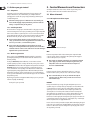
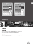
User Manual EURORACK UB1222 -PRO Ultra-Low Noise Design 16-Input 2/2-Bus Mic/Line Mixer with Premium Mic Preamplifiers and Multi-FX Processor 2 EURORACK UB1222FX-PRO User Manual Table of Contents Important Safety Instructions....................................... 3 Legal Disclaimer.............................................................. 3 Limited Warranty............................................................ 3 1. Introduction................................................................ 5 1.1 General mixing console functions ................................ 5 1.2 The user’s manual................................................................ 5 1.3 Before you get started....................................................... 6 2. Control Elements and Connectors ........................... 6 2.1 Mono channels..................................................................... 6 2.2 Stereo channels.................................................................... 8 2.3 Connector panel and main section.............................. 8 2.4 Graphic 7-band equalizer............................................... 11 2.5 Rear view of UB1222FX-PRO.......................................... 12 3. Digital Effects Processor and XPQ Surround Function................................................ 12 3.1 Digital effects processor.................................................. 12 3.2 XPQ surround function................................................... 13 4. Installation................................................................ 13 4.1 Rack mounting.................................................................... 13 4.2 Cable connections............................................................ 13 5. Specifications............................................................ 14 3 EURORACK UB1222FX-PRO User Manual Important Safety Instructions Terminals marked with this symbol carry electrical current of sufficient magnitude to constitute risk of electric shock. Use only high-quality professional speaker cables with ¼" TS or twist-locking plugs pre-installed. All other installation or modification should be performed only by qualified personnel. This symbol, wherever it appears, alerts you to the presence of uninsulated dangerous voltage inside the enclosure - voltage that may be sufficient to constitute a risk of shock. This symbol, wherever it appears, alerts you to important operating and maintenance instructions in the accompanying literature. Please read the manual. Caution To reduce the risk of electric shock, do not remove the top cover (or the rear section). No user serviceable parts inside. Refer servicing to qualified personnel. Caution To reduce the risk of fire or electric shock, do not expose this appliance to rain and moisture. The apparatus shall not be exposed to dripping or splashing liquids and no objects filled with liquids, such as vases, shall be placed on the apparatus. 9. Do not defeat the safety purpose of the polarized or grounding-type plug. A polarized plug has two blades with one wider than the other. A grounding-type plug has two blades and a third grounding prong. The wide blade or the third prong are provided for your safety. If the provided plug does not fit into your outlet, consult an electrician for replacement of the obsolete outlet. 10. Protect the power cord from being walked on or pinched particularly at plugs, convenience receptacles, and the point where they exit from the apparatus. 11. Use only attachments/accessories specified by the manufacturer. 12. Use only with the cart, stand, tripod, bracket, or table specified by the manufacturer, or sold with the apparatus. When a cart is used, use caution when moving the cart/apparatus combination to avoid injury from tip-over. 13. Unplug this apparatus during lightning storms or when unused for long periods of time. 14. Refer all servicing to qualified service personnel. Servicing is required when the apparatus has been damaged in any way, such as power supply cord or plug is damaged, liquid has been spilled or objects have fallen into the apparatus, the apparatus has been exposed to rain or moisture, does not operate normally, or has been dropped. 15. The apparatus shall be connected to a MAINS socket outlet with a protective earthing connection. 16. Where the MAINS plug or an appliance coupler is used as the disconnect device, the disconnect device shall remain readily operable. Caution These service instructions are for use by qualified service personnel only. To reduce the risk of electric shock do not perform any servicing other than that contained in the operation instructions. Repairs have to be performed by qualified service personnel. 1. Read these instructions. 2. Keep these instructions. 3. Heed all warnings. 4. Follow all instructions. 5. Do not use this apparatus near water. 6. Clean only with dry cloth. 7. Do not block any ventilation openings. Install in accordance with the manufacturer’s instructions. 8. Do not install near any heat sources such as radiators, heat registers, stoves, or other apparatus (including amplifiers) that produce heat. LEGAL DISCLAIMER TECHNICAL SPECIFICATIONS AND APPEARANCES ARE SUBJECT TO CHANGE WITHOUT NOTICE AND ACCURACY IS NOT GUARANTEED. BEHRINGER IS PART OF THE MUSIC GROUP (MUSIC-GROUP.COM). ALL TRADEMARKS ARE THE PROPERTY OF THEIR RESPECTIVE OWNERS. MUSIC GROUP ACCEPTS NO LIABILITY FOR ANY LOSS WHICH MAY BE SUFFERED BY ANY PERSON WHO RELIES EITHER WHOLLY OR IN PART UPON ANY DESCRIPTION, PHOTOGRAPH OR STATEMENT CONTAINED HEREIN. COLORS AND SPECIFICATIONS MAY VARY FROM ACTUAL PRODUCT. MUSIC GROUP PRODUCTS ARE SOLD THROUGH AUTHORIZED FULLFILLERS AND RESELLERS ONLY. FULLFILLERS AND RESELLERS ARE NOT AGENTS OF MUSIC GROUP AND HAVE ABSOLUTELY NO AUTHORITY TO BIND MUSIC GROUP BY ANY EXPRESS OR IMPLIED UNDERTAKING OR REPRESENTATION. THIS MANUAL IS COPYRIGHTED. NO PART OF THIS MANUAL MAY BE REPRODUCED OR TRANSMITTED IN ANY FORM OR BY ANY MEANS, ELECTRONIC OR MECHANICAL, INCLUDING PHOTOCOPYING AND RECORDING OF ANY KIND, FOR ANY PURPOSE, WITHOUT THE EXPRESS WRITTEN PERMISSION OF MUSIC GROUP IP LTD. ALL RIGHTS RESERVED. © 2012 MUSIC Group IP Ltd. Trident Chambers, Wickhams Cay, P.O. Box 146, Road Town, Tortola, British Virgin Islands LIMITED WARRANTY § 1 Warranty (1) This limited warranty is valid only if you purchased the product from a MUSIC Group Authorized Reseller in the country of purchase. A list of authorized resellers can be found on BEHRINGER’s website behringer.com under “Where to Buy”, or you can contact the MUSIC Group office closest to you. (2) MUSIC Group* warrants the mechanical and electronic components of this product to be free of defects in material and workmanship if used under normal operating conditions for a period of one (1) year from the original date of purchase (see the Limited Warranty terms in § 4 below), unless a longer minimum warranty period is mandated by applicable local laws. If the product shows any defects within the specified warranty period and that defect is not excluded under § 4, MUSIC Group shall, at its discretion, either replace or repair the product using suitable new or reconditioned product or parts. In case MUSIC Group decides to replace the entire product, this limited warranty shall apply to the replacement product for the remaining initial warranty period, i.e., one (1) year (or otherwise applicable minimum warranty period) from the date of purchase of the original product. (3) Upon validation of the warranty claim, the repaired or replacement product will be returned to the user freight prepaid by MUSIC Group. (4) Warranty claims other than those indicated above are expressly excluded. PLEASE RETAIN YOUR SALES RECEIPT. IT IS YOUR PROOF OF PURCHASE COVERING YOUR LIMITED WARRANTY. THIS LIMITED WARRANTY IS VOID WITHOUT SUCH PROOF OF PURCHASE. § 2 Online registration Please do remember to register your new BEHRINGER equipment right after your purchase at behringer.com under “Support” and kindly read the terms and conditions of our limited warranty carefully. Registering your purchase and equipment with us helps us process your repair claims quicker and more efficiently. Thank you for your cooperation! § 3 Return materials authorization (1) To obtain warranty service, please contact the retailer from whom the equipment was purchased. Should your MUSIC Group Authorized Reseller not be located in your vicinity, you may contact the MUSIC Group Authorized Fulfiller for your country listed under 4 EURORACK UB1222FX-PRO User Manual “Support” at behringer.com. If your country is not listed, please check if your problem can be dealt with by our “Online Support” which may also be found under “Support” at behringer.com. Alternatively, please submit an online warranty claim at behringer.com BEFORE returning the product. All inquiries must be accompanied by a description of the problem and the serial number of the product. After verifying the product’s warranty eligibility with the original sales receipt, MUSIC Group will then issue a Return Materials Authorization (“RMA”) number. (2) Subsequently, the product must be returned in its original shipping carton, together with the return authorization number to the address indicated by MUSIC Group. (3) Shipments without freight prepaid will not be accepted. § 4 Warranty Exclusions (1) This limited warranty does not cover consumable parts including, but not limited to, fuses and batteries. Where applicable, MUSIC Group warrants the valves or meters contained in the product to be free from defects in material and workmanship for a period of ninety (90) days from date of purchase. (2) This limited warranty does not cover the product if it has been electronically or mechanically modified in any way. If the product needs to be modified or adapted in order to comply with applicable technical or safety standards on a national or local level, in any country which is not the country for which the product was originally developed and manufactured, this modification/adaptation shall not be considered a defect in materials or workmanship. This limited warranty does not cover any such modification/adaptation, regardless of whether it was carried out properly or not. Under the terms of this limited warranty, MUSIC Group shall not be held responsible for any cost resulting from such a modification/adaptation. (3) This limited warranty covers only the product hardware. It does not cover technical assistance for hardware or software usage and it does not cover any software products whether or not contained in the product. Any such software is provided “AS IS” unless expressly provided for in any enclosed software limited warranty. (4) This limited warranty is invalid if the factory-applied serial number has been altered or removed from the product. (5) Free inspections and maintenance/repair work are expressly excluded from this limited warranty, in particular, if caused by improper handling of the product by the user. This also applies to defects caused by normal wear and tear, in particular, of faders, crossfaders, potentiometers, keys/buttons, guitar strings, illuminants and similar parts. (6) Damage/defects caused by the following conditions are not covered by this limited warranty: • improper handling, neglect or failure to operate the unit in compliance with the instructions given in BEHRINGER user or service manuals; • connection or operation of the unit in any way that does not comply with the technical or safety regulations applicable in the country where the product is used; • damage/defects caused by acts of God/Nature (accident, fire, flood, etc) or any other condition that is beyond the control of MUSIC Group. (7) Any repair or opening of the unit carried out by unauthorized personnel (user included) will void the limited warranty. (8) If an inspection of the product by MUSIC Group shows that the defect in question is not covered by the limited warranty, the inspection costs are payable by the customer. (9) Products which do not meet the terms of this limited warranty will be repaired exclusively at the buyer’s expense. MUSIC Group or its authorized service center will inform the buyer of any such circumstance. If the buyer fails to submit a written repair order within 6 weeks after notification, MUSIC Group will return the unit C.O.D. with a separate invoice for freight and packing. Such costs will also be invoiced separately when the buyer has sent in a written repair order. (10) MUSIC Group Authorized Resellers do not sell new products directly in online auctions. Purchases made through an online auction are on a “buyer beware” basis. Online auction confirmations or sales receipts are not accepted for warranty verification and MUSIC Group will not repair or replace any product purchased through an online auction. § 5 Warranty transferability This limited warranty is extended exclusively to the original buyer (customer of authorized reseller) and is not transferable to anyone who may subsequently purchase this product. No other person (reseller, etc.) shall be entitled to give any warranty promise on behalf of MUSIC Group. § 6 Claim for damage Subject only to the operation of mandatory applicable local laws, MUSIC Group shall have no liability to the buyer under this warranty for any consequential or indirect loss or damage of any kind. In no event shall the liability of MUSIC Group under this limited warranty exceed the invoiced value of the product. § 7 Limitation of liability This limited warranty is the complete and exclusive warranty between you and MUSIC Group. It supersedes all other written or oral communications related to this product. MUSIC Group provides no other warranties for this product. § 8 Other warranty rights and national law (1) This limited warranty does not exclude or limit the buyer’s statutory rights as a consumer in any way. (2) The limited warranty regulations mentioned herein are applicable unless they constitute an infringement of applicable mandatory local laws. (3) This warranty does not detract from the seller’s obligations in regard to any lack of conformity of the product and any hidden defect. § 9 Amendment Warranty service conditions are subject to change without notice. For the latest warranty terms and conditions and additional information regarding MUSIC Group’s limited warranty, please see complete details online at behringer.com. * MUSIC Group Macao Commercial Offshore Limited of Rue de Pequim No. 202-A, Macau Finance Centre 9/J, Macau, including all MUSIC Group companies 5 EURORACK UB1222FX-PRO User Manual 1. Introduction Congratulations! In purchasing the BEHRINGER EURORACK you have acquired a mixer whose small size belies its incredible versatility and audio performance. The BEHRINGER EURORACK mixing console offers you premium-quality microphone preamplifiers with optional phantom power supply, balanced line inputs and the ability to connect external effects devices. Because of its extensive and carefully thought-out routing possibilities, your EURORACK lends itself equally to both live and studio use. FBQ Feedback Detection System The FBQ Feedback Detection System, integrated into the graphic equalizer, is one of the most outstanding characteristics of this mixing console. This ingenious circuitry lets you immediately recognize and eliminate feedback frequencies. The FBQ Feedback Detection System uses the LEDs in the frequency band faders of the graphic EQ to indicate the critical frequencies. This way, what once used to be a labor-intensive search for feedback frequencies is now an activity that even a child could master. IMP “Invisible” Mic Preamp The microphone channels are fitted with BEHRINGER’s brand new high-end IMP INVISIBLE MIC PREAMPs that boast the following features: • 130 dB dynamic range for an incredible amount of headroom • a bandwidth ranging from below 10 Hz to over 200 kHz for crystal-clear reproduction of even the finest nuances • the extremely low-noise and distortionless circuitry guarantees absolutely natural and transparent signal reproduction • they are perfectly matched to every conceivable microphone with up to 60 dB gain and +48 volt phantom power supply and • they enable full utilisation of the greatly extended dynamic range of your 24-bit/192 kHz HD recorder, thereby maintaining optimal audio quality Additionally, your UB mixing console has an effects processor with 24-bit A/D and D/A converters included, which gives you 100 presets producing first-class reverb, delay and modulation effects plus numerous multi-effects in excellent audio quality. The mixing consoles of the PRO series feature a state of the art, integrated switchmode power supply. One of the great advantages is that (compared to conventional circuits) a switch-mode power supply adapts to mains voltages between 100 and 240 volts automatically. Furthermore, due to its much greater efficiency, it consumes much less energy than a conventional power supply unit. CAUTION! interference. Therefore, mic signal voltage is amplified directly at the mixer input to a higher signal level that is less prone to interference. This higher, interference-safe signal level has to be achieved through amplification using an amplifier of the highest quality in order to amplify the signal and add as little noise to it as possible. The IMP “Invisible” Mic Preamp performs this role beautifully, leaving no traces of noise or sound coloration. Interference that could take place at the preamplification level could affect signal quality and purity, and would then be passed on to all other devices, resulting in inaccurate sounding program during recording or playback. Level-setting Signals fed into the mixer using a DI-box (Direct Injection) or the output of a sound card or a keyboard, often have to be adjusted to the operating level of your mixing console. Frequency response correction Using the equalizers found in each channel strip, you can simply, quickly and effectively adjust the way a signal sounds. Effects mixing In addition to the effects processor contained in your mixer, using the insert connectors on the mono channels and both aux busses lets you insert additional signal processors into your signal path. • Signal distribution: Individual signals adjusted at each channel strip are laid out at the aux sends and returns, and are either fed into external effects processors or fed back to the internal effects processor. Then, the signals are brought back into the main mix either via the aux return connectors or via direct internal wiring. The mix for the on-stage musicians is also created using the aux sends (monitor mix). Similarly, for example, signals for recording equipment, power amplifiers, headphones and 2-track outputs can also be taken. • Mix: All other mixing console functions fall under this vital category. Creating a mix means primarily adjusting the volume levels of individual instruments and voices to one another as well as giving them the appropriate weight within the overall frequency spectrum. Likewise, you’ll have to sensibly spread individual voices across the stereo image of a signal. At the end of this process, adjusting the level of the entire mix to other equipment in the signal path is required (e. g. recorder/crossover/amplifier). The interface of BEHRINGER mixing consoles is optimized for these tasks, enabling you to easily keep track of the signal path. 1.2 The user’s manual 1.1 General mixing console functions The user’s manual is designed to give you both an overview of the controls, as well as detailed information on how to use them. In order to help you understand the links between the controls, we have arranged them in groups according to their function. If you need to know more about specific issues, please visit our website at http://behringer.com. Additional information and explanations about various music industry/audio technology terminology can be found on individual product pages as well as in the glossary in the ULTRANET area of behringer.com. A mixing console fulfils three main functions: ◊ The block diagram supplied with the mixing console gives you an ◊ We would like to draw your attention to the fact that extreme volumes may damage your hearing and/or your headphones or loudspeakers. Turn the MAIN MIX faders and the PHIONES control in the main section fully down before you switch on the unit. Always be careful to set the appropriate volume. • Signal processing: Preamplification Microphones convert sound waves into voltage that has to be amplified several-fold; then, this voltage is turned into sound that is reproduced in a loudspeaker. Because microphone capsules are very delicate in their construction, output voltage is very low and therefore susceptible to overview of the connections between the inputs and outputs, as well as the associated switches and controls. For the moment, just try and trace the signal path from the microphone input to the MON SEND connector. Don’t be put off by the huge range of possibilities; it’s easier than you think! If you look at the overview of the controls at the same time, you’ll be able to quickly familiarize yourself with your mixing console and you’ll soon be making the most of all its many possibilities. 6 EURORACK UB1222FX-PRO User Manual 1.3 Before you get started 2. Control Elements and Connectors 1.3.1 Shipment This chapter describes the various control elements of your mixing console. All controls, switches and connectors will be discussed in detail. Your mixing console was carefully packed in the factory to guarantee safe transport. Nevertheless, we recommend that you carefully examine the packaging and its contents for any signs of physical damage, which may have occurred during transit. 2.1 Mono channels 2.1.1 Microphone and line inputs ◊ If the unit is damaged, please do NOT return it to us, but notify your dealer and the shipping company immediately, otherwise claims for damage or replacement may not be granted. 1.3.2 Initial operation Be sure that there is enough space around the unit for cooling purposes and to avoid over-heating. Please do not place your mixing console on high-temperature devices such as radiators or power amps. The console is connected to the mains via the supplied power cable. The console meets the required safety standards. Blown fuses must only be replaced by fuses of the same type and rating. ◊ Please note that all units must be properly grounded. For your own safety, you should never remove any ground connectors from electrical devices or power cables, or render them inoperative. ◊ Please ensure that only qualified people install and operate the mixing console. During installation and operation, the user must have sufficient electrical contact to earth, otherwise electrostatic discharges might affect the operation of the unit. 1.3.3 Online registration Please register your new BEHRINGER equipment right after your purchase by visiting http://behringer.com and read the terms and conditions of our warranty carefully. Should your BEHRINGER product malfunction, it is our intention to have it repaired as quickly as possible. To arrange for warranty service, please contact the BEHRINGER retailer from whom the equipment was purchased. Should your BEHRINGER dealer not be located in your vicinity, you may directly contact one of our subsidiaries. Corresponding contact information is included in the original equipment packaging (Global Contact Information/European Contact Information). Should your country not be listed, please contact the distributor nearest you. A list of distributors can be found in the support area of our website (http://behringer.com). Registering your purchase and equipment with us helps us process your repair claims more quickly and efficiently. Thank you for your cooperation! Fig. 2.1: Connectors and controls of mic/line inputs MIC Each mono input channel offers a balanced microphone input via the XLR connector and also features a switchable +48 V phantom power supply for condenser microphones (see rear panel). ◊ Please mute your playback system before you activate the phantom power supply to prevent switch-on thumps being directed to your loudspeakers. Please also note the instructions in chapter 2.5 “Rear view of UB1222FX-PRO”. LINE IN Each mono input also features a balanced line input on a 1/4" connector. Unbalanced devices (mono jacks) can also be connected to these inputs. ◊ Please remember that you can only use either the microphone or the line input of a channel at any one time. You can never use both simultaneously! INSERT Insert points enable the processing of a signal with dynamic processors or equalizers. They are sourced pre-fader, pre-EQ and pre-aux send. Unlike reverb or other effects devices, whose signals are usually added to the dry signal, dynamic processors are most effective on the complete signal. In this case, aux send paths are a less-than-perfect solution. It is better to interrupt the signal path and insert a dynamic processor and/or equalizer. After processing, the signal is routed back to the console at precisely the same point it left. However, the channel signal path is interrupted only if a plug is inserted into the corresponding jack (stereo phone plug: tip = signal output; ring = return input). All mono input channels are equipped with inserts. Inserts can also be used as pre-EQ direct outputs, without interrupting the signal path. To this end, you will need a cable fitted with mono phone plugs on the tape machine or effects device end, and a bridged stereo phone plug on the console side (tip and ring connected). 7 EURORACK UB1222FX-PRO User Manual LOW CUT The mono channels of the mixing consoles have a high-slope LOW CUT filter for eliminating unwanted, low-frequency signal components (80 Hz, 18 dB/octave). TRIM Use the TRIM control to adjust the input gain. This control should always be turned fully counter-clockwise whenever you connect or disconnect a signal source to one of the inputs. The scale has 2 different value ranges: the first value range (+10 to +60 dB) refers to the MIC input and shows the amplification for the signals fed in there. The second value range (+10 to -40 dBu) refers to the line input and shows its sensitivity. The settings for equipment with standard line-level signals (-10 dBV or +4 dBu) look like this: While the TRIM control is turned all the way down, connect your equipment. Set the TRIM control to the external devices’ standard output level. If that unit has an output signal level display, it should show 0 dB during signal peaks. For +4 dBu, turn up TRIM slightly, for -10 dBV a bit more. Tweaking is done using the LEVEL SET LED. LEVEL SET This LED lights up when the optimum operating signal level is achieved. During normal use, this LED should only light up during signal peaks. 2.1.2 Equalizer All mono input channels include a 3-band equalizer. All bands provide boost or cut of up to 15 dB. In the central position, the equalizer is inactive. For situations that require effects processing, the aux sends are usually switched post-fader so that the effects volume in a channel corresponds to the position of the channel fader. If this were not the case, the effects signal of the channel would remain audible even when the fader is turned to zero. When setting up a monitor mix, the aux sends are generally switched to pre-fader; i.e. they operate independently of the position of the channel fader. Both aux sends are mono, are sourced after the equalizer and offer up to +15 dB gain. ◊ If you press the MUTE switch of the respective channel, aux sends and returns (MON and FX) are not being muted. MON In the UB1222FX-PRO, aux send 1 (MON) is wired pre-fader and is thus particularly suitable for setting up monitor mixes. FX The aux send labeled FX is for feeding external effects devices and is thus set up to be post-fader. In the UB1222FX-PRO, the FX send is routed directly to the built-in effects processor. To make sure that the effects processor receives an input signal, you shouldn’t turn this control all the way to the left (-∞). Don’t have the FX MUTE switch pressed, and you should also not have the FX SEND fader pulled down. 2.1.4 Pan, mute switch and channel fader Fig. 2.2: The equalizer of the input channels The upper (HIGH) and the lower band (LOW) are shelving filters that increase or decrease all frequencies above or below their cut-off frequency. The cut-off frequencies of the upper and lower band are 12 kHz and 80 Hz respectively. The mid band is configured as a peak filter with a center frequency of 2.5 kHz. Unlike shelving filters, the peak filter processes a frequency range that extends upwards and downwards around its middle frequency. 2.1.3 Aux sends (MON and FX) Fig. 2.4: Channel fader and additional control elements PAN Fig. 2.3: The AUX SEND controls in the channel strips Aux sends take signals via a control from one or more channels and sum these signals to a so-called bus. This bus signal is sent to an aux send connector and then routed, for example, to an active monitor speaker or an external effects device. The return from an external effects device can then be brought back into the console via the aux return connectors. The PAN control determines the position of the channel signal within the stereo image. This control features a constant-power characteristic, which means the signal is always maintained at a constant level, irrespective of position in the stereo panorama. MUTE Use the MUTE switch to mute the channel. This means that the channel signal is no longer present in the main mix. However, the aux sends (MON and FX) remain active. 8 EURORACK UB1222FX-PRO User Manual MUTE LED 2.2.3 Aux sends stereo channels The MUTE LED indicates that the relevant channel is muted. In principle, the aux sends of the stereo channels function in just the same way as those of the mono channels. As aux send paths are always mono, the signal on a stereo channel is first summed to mono before it reaches the aux bus. CLIP LED The CLIP LED lights up when the input signal is driven too high. In this case, lower apparent frequency increase on the channel EQ to avoid distortion. For example, lower the mids and the highs somewhat to emphasize the bass. If you don’t wish to change the EQ settings under any circumstances, try lowering the TRIM control somewhat (counterclockwise). If you inserted an external effects processor via the insert connector (e. g. a dynamic processor), then you should also control its output signal level. It should not be higher than its input signal level (0 dB). The channel fader determines the level of the channel signal in the main mix. ◊ Attention: Since the aux path for the effect processor is connected post-fader, the channel fader has to be turned up in order to get this channel’s signal to the effects processor! 2.2 Stereo channels 2.2.1 Channel inputs 2.2.4 Balance, mute switch and channel fader BAL The function of the BAL(ANCE) control corresponds to the PAN control in the mono channels. The balance control determines the relative proportion between the left and right input signals before both signals are routed to the main stereo mix bus. The MUTE switch, MUTE LED, CLIP LED and channel fader function in the same way as the mono channels. 2.3 Connector panel and main section Whereas it was useful to trace the signal flow from top to bottom in order to gain an understanding of the channel strips, we now look at the mixing console from left to right. The signals are, so to speak, collected from one point on each of the channel strips and then routed to the main section all together. 2.3.1 Monitor send and FX send channels 0 0 FX TO MON FX TO MAIN +15 MON MUTE Fig. 2.5: Stereo channel inputs Each stereo channel features two line-level inputs on 1/4" connectors for left and right channels. Channels 9/10 and 11/12 can also be used in mono if you only use the connector labeled “L.” Both channels 5/6 and 7/8 feature an additional balanced XLR input for microphones with available +48 V phantom power. All stereo channel strips have a TRIM control for level setting. In those channels in which a mic input is present in the channel, the TRIM control has two scales: just like in the mono channels, there is a 0 to +40 dB scale that shows the preamplification of the mic signal; the +20 to -20 dB scale shows the sensitivity for the corresponding input level that is applied to the line input. Both inputs can also be used with balanced or unbalanced connectors. 2.2.2 Equalizer stereo channels The equalizer of the stereo channels is, of course, stereo. The filter characteristics and crossover frequencies are the same as those of the mono channels. A stereo equalizer is always preferable to two mono equalizers if frequency correction of a stereo signal is needed. There is often a discrepancy between the settings of the left and the right channels when using separate equalizers. +15 FX MUTE 10 10 0 0 10 10 15 15 20 20 25 25 30 30 40 60 40 60 MON SEND F X SEND Fig. 2.6: Aux send controls of the main section A channel signal is routed to the MON(ITOR) send bus if the MON control is turned up on the corresponding channel. MON SEND The aux send control MON SEND acts as master control for the monitor bus and determines the level of the summed signal that is taken from the mixer via the MON SEND connector and that can for example be fed to an amplifier for monitor purposes. Using the audio signal from this output, you can also feed a subwoofer if you don’t require stage monitors. To this end, you should implement a crossover in your signal path pre-subwoofer and pre-amplifier, so that only low frequencies are fed into the subwoofer. You can achieve the same effect by using the built-in graphical equalizer. Lower all frequencies above 160 Hz and assign the equalizer to “Monitor”. 9 EURORACK UB1222FX-PRO User Manual ◊ When you use the MAIN MIX fader to reduce the overall volume, keep in mind that the subwoofer is still receiving a signal! 2.3.3 Aux return connectors 1 L FX TO MON You can use this control to insert an effects signal from the built-in effects processor to your monitor mix. Of course, to do this, your effects processor must first receive a signal, i.e. the FX controls in the channel strips must be turned up, and the FX SEND fader (see fig. 2.6) hast to be open. L (MONO) AUX RTN R R 2 Fig. 2.8: Aux return connectors MON MUTE AUX RETURN 1 If the MON MUTE switch is pressed, the monitor bus is muted, i.e. there is no signal at the MON SEND connector. The AUX RETURN 1 connectors generally serve as the return path for the effects mix generated using the FX send. This is where you connect the output signal of the external effects device. If only the left connector is used, the aux return 1 automatically operates in mono. FX SEND The FX SEND fader determines the overall level of the effects bus. Both external effects processors (via the FX SEND connector) and the built-in processor only receive an input signal if this control is open. FX TO MAIN Use the FX TO MAIN control to feed the effects signal into the main mix. If the control is turned all the way to the left, no effects signal can be heard. FX MUTE If the FX MUTE switch is pressed, the effects channel is muted, i.e. no signal is present at the FX SEND connector and the effects processor no longer receives an input signal. 2.3.2 Monitor send and FX send connector ◊ You can also use these connectors as additional line inputs. AUX RETURN 2 The AUX RETURN 2 connectors are used exactly the same way as the AUX RETURN 1 connectors. If these connectors already function as additional inputs, you can route the effects signal back into the console via a different stereo channel, with the added benefit that the channel EQ can be used to adjust the frequency response of the effects return signal. ◊ In this instance, the FX control of the channel being used as an effects return should be turned fully counter-clockwise, otherwise feedback problems can occur! 2.3.4 2-Track return channel, voice canceller and connection socket MON SEND Fig. 2.7: Aux send connectors MON and FX MON SEND Connect the input of your monitor power amp or an active monitor system here to make the monitor mix audible to the musicians on the stage. The signal mix is created using the channels’ MON controls. FX SEND The FX SEND connector outputs the signal you picked up from the individual channels using the FX controls. You can connect this to the input of an external effects device in order to process the FX bus’ master signal. Once an effects mix is created, the processed signal can then be routed from the effects device outputs back into the AUX RETURN connectors. ◊ If the connected effects processor receives no input signal, the FX MUTE switch is probably pressed and/or the FX SEND control is too low. This also goes for the built-in effects processor. ◊ Adjust your external effects processor to 100% wet (effects signal only), because the effects signal is added to the main mix along with the “dry” channel signals. Fig. 2.9: 2-Track return channel This channel, intended especially for connecting stereo signal sources (CD players, DAT recorders or even sound cards) features a particularly practical feature: the VOICE CANCELLER. VOICE CANCELLER Here, you have a filter circuitry that lets you almost entirely remove the vocal portion of a recording. The filter is constructed in such a way that voice frequencies are targeted without majorly affecting the rest of the signal. Additionally, the filter seizes only the middle of the stereo image, exactly there where the vocals are typically located. 10 EURORACK UB1222FX-PRO User Manual Possible applications for the Voice Canceller are obvious: you can very simply stage background music for Karaoke events. Of course, you can also do this at home or at your rehearsal room before you hit the stage. Singers with their own band can practice singing difficult parts using a complete playback from a tape player or a CD, thus minimizing rehearsal time. MAIN MIX If the STANDBY switch is pressed, all input channels with a mic connector (XLR connector) are muted. During breaks or stage conversion, you can prevent noise from entering the sound system via the microphones. Such noise can in the worst-case scenario even irreparably damage loudspeaker membranes. The cool thing about this is that the main mix faders can remain open, so that you can play music from a CD at the same time. Similarly, the faders for the muted channels can also remain in their position. To bring in other sound sources, you can use the 2-track inputs, stereo input channels 9 to 12 and the aux return inputs. 2-TRACK MUTE Using this switch, the input signal from the 2-track inputs is muted. 2-TRACK RET(URN) This stereo fader assigns the input signal from the 2-track inputs into the main mix. L 2 – TR R PHONES MA X STANDBY INPUT 2.3.5 Main mix, main out connectors and headphone connector OUTPUT LEFT RIGHT 10 0 10 15 20 25 30 40 60 MAIN MIX Fig. 2.11: Main mix fader MAIN MIX Use the high-precision quality faders to control the output level of the main mix. L 2 – TR R MAIN OUT LEFT BAL OR UNBAL RIGHT Fig. 2.10: 2-track connectors 2-TRACK INPUT The 2-TRACK INPUT RCA connectors are provided for connecting a 2-track machine (e.g. DAT recorder) or also a CD player. They can also be used as stereo line input. Alternatively, the output signal of a second EURORACK or BEHRINGER ULTRALINK PRO MX882 can also be connected. If you connect a hi-fi amplifier with a source selection switch to the 2-TRACK INPUT, you can easily switch between additional sources (e.g. cassette recorder, MD player, sound card etc.). Using the voice canceller function, you can process all signals being brought into your mixing console via these connectors. 2-TRACK OUTPUT These connectors are wired pre graphic EQ and pre XPQ surround function. They carry the main mix signal (unbalanced), effects mix included. Connect the 2-TRACK OUTPUT to the inputs of your recording device. If you wish to use your mixer solely for recording purposes, the main outputs are also an alternative. Fig. 2.12: Main out connectors MAIN OUT The MAIN outputs carry the MAIN MIX signal and are on balanced XLR connectors with a nominal level of +4 dBu. Depending on how you wish to use your mixer and which gear you own, you can connect the following equipment: Live PA systems: A stereo dynamics processor (optional), stereo equalizer (optional) and the stereo power amplifier for full-range loud-speakers with passive crossovers. If you wish to use multi-way loudspeaker systems without an integrated crossover, you have to use an active crossover and several power amplifiers. Often, limiters are already built into active crossovers (e.g. BEHRINGER SUPER-X PRO CX2310 and ULTRADRIVE PRO DCX2496). Active crossovers are implemented directly before the power amplifier, and they divide the frequency range into several segments that are first amplified in the amplifiers and then passed onto the corresponding loudspeakers. Recording: For mastering, using a stereo compressor such as the COMPOSER PRO-XL MDX2600 can be recommended. Use it to custom-tailor the dynamic characteristics of your signal to the dynamic range of the recording equipment you are using. The signal is in this case passed on from the compressor into the recorder. 11 EURORACK UB1222FX-PRO User Manual PHONES LEVEL METER/CLIP The PHONES control adjusts the volume of the headphones connected to the PHONES/CTRL connector. If you connect active monitors or an amplifier, use this connector to adjust the output signal level. The high-precision level meter accurately displays the appropriate signal level. CAUTION! ◊ We would like to draw your attention to the fact that extreme volumes may damage your hearing and/or your headphones or loudspeakers. Turn the MAIN MIX faders and the PHONES control in the main section fully down before you switch on the unit. Always be careful to set the appropriate volume. PHONS / CTRL LEVEL SETTING: When recording to a digital device, the recorder’s peak meter should not exceed 0 dB. This is because, unlike analog recordings, slightly excessive levels can create unpleasant digital distortion. When recording to an analog device, the VU meters of the recording machine should reach approx. +3 dB with low-frequency signals (e.g. kick drum). Due to their inertia VU meters tend to display too low a signal level at frequencies above 1 kHz. This is why, for example, a Hi-Hat should only be driven as far as -10 dB. Snare drums should be driven to approx. 0 dB. ◊ The peak meters of your EURORACK display the level virtually Fig. 2.13: PHONES/CTRL connector PHONES/CTRL connector You can connect headphones to this 1/4" TRS connector. The connector can also be used for feeding active monitor loudspeakers (or an amplifier) in your control room. For this purpose, the signal is taken directly before it is passed on to the main mix faders. independent of frequency. A recording level of 0 dB is recommended for all signal types. 2.4 Graphic 7-band equalizer +12 +12 +6 +6 0 0 –6 2.3.6 Level meter and level setting –6 –12 –12 63 POWER + 48 V CLIP 160 400 1k 2.5k FBQ FEEDBACK DETECTION 6.3k MAIN MIX MONITOR 16k EQ IN Fig. 2.15: The graphic stereo equalizer 10 7 The graphic stereo equalizer allows you to tailor the sound to the room acoustics. 4 2 0 FBQ FEEDBACK DETECTION 2 4 7 10 20 30 L R Fig. 2.14: Level meter The switch turns on the FBQ Feedback Detection System. It uses the LEDs in the frequency band faders to indicate the critical frequencies. On a per-need basis, lower the frequency range in question somewhat in order to avoid feedback. The graphic stereo equalizer has to be turned on in order to use this function. ◊ Logically, at least one (ideally several) microphone channels have to be open for feedback to occur at all! POWER The blue POWER LED indicates that the device is switched on. +48 V The red “+48 V” LED lights up when the phantom power supply is switched on. The phantom power supply is necessary for condenser microphones and is activated using the corresponding switch on the rear of the device. ◊ Connect microphones before you switch on the phantom power supply. Please do not connect microphones to the mixer (or the stagebox/wallbox) while the phantom power supply is switched on. In addition, the monitor/PA loudspeakers should be muted before you activate the phantom power supply. After switching on, wait approx. one minute to allow for system stabilization. Feedback is particularly common when stage monitors (“wedges”) are concerned, because monitors project sound in the direction of microphones. Therefore, you can also use the FBQ Feedback Detection for monitors by placing the equalizer in the monitor bus (see MAIN MIX/MONITOR). EQ IN Use this switch to activate the graphic equalizer. When activated, the fader LEDs will illuminate. MAIN MIX/MONITOR This toggles the graphic equalizer between the main mix and the monitor mix. With the switch up (not depressed), the equalizer is active in stereo on the main mix, and inactive on the monitor mix. When the switch is depressed the equalizer is active in mono on the monitor mix, and inactive on the main mix. 12 EURORACK UB1222FX-PRO User Manual 2.5 Rear view of UB1222FX-PRO 3. Digital Effects Processor and XPQ Surround Function 3.1 Digital effects processor 24 – BIT MULTI – F X PROCESSOR Fig. 2.16: Voltage supply and fuse FUSE HOLDER/IEC MAINS RECEPTACLE The console is connected to the mains via the cable supplied, which meets the required safety standards. Blown fuses must only be replaced by fuses of the same type and rating. The mains connection is made via a cable with IEC mains connector. An appropriate mains cable is supplied with the equipment. POWER Use the POWER switch to power up the mixing console. The POWER switch should always be in the “Off” position when you are about to connect your unit to the mains. To disconnect the unit from the mains, pull out the main cord plug. When installing the product, ensure that the plug is easily accessible. If mounting in a rack, ensure that the mains can be easily disconnected by a plug pull or by an all-pole disconnect switch on or near the rack. ◊ Attention: The POWER switch does not fully disconnect the unit from the mains. Unplug the power cord completely when the unit is not used for prolonged periods of time. PHANTOM The PHANTOM switch activates the phantom power supply for the XLR microphone inputs, which is required to operate condenser microphones. The red +48 V LED lights up when phantom power is on. As a rule, dynamic microphones can still be used with phantom power switched on, provided that they are wired in a balanced configuration. In case of doubt, contact the microphone manufacturer! ◊ Connect microphones before you switch on the phantom power supply. Please do not connect microphones to the mixer (or the stagebox/wallbox) while the phantom power supply is switched on. In addition, the monitor/PA loudspeakers should be muted before you activate the phantom power supply. After switching on, wait approx. one minute to allow for system stabilization. 00 03 06 09 10 13 16 19 20 27 30 SMALL HALL MID HALL BIG HALL CHURCH SMALL ROOM MID ROOM BIG ROOM CHAPEL PLATE SPRING GATED REV 36 40 44 48 49 50 59 60 66 70 74 REVERSE EARLY REFL AMBIENCE STADIUM AMBIENCE FX DELAY ECHO CHORUS FLANGER PHASER PITCH SHIFT 80 82 84 86 88 90 91 92 94 96 98 CHORUS & REVERB FLANGER & REVERB PHASER & REVERB PITCH & REVERB DELAY & REVERB DELAY & GATED DELAY & REVERSE DELAY & CHORUS DELAY & FLANGER DELAY & PHASER DELAY & PITCH Fig. 3.1: Effects presets overview 24-BIT MULTI-EFFECTS PROCESSOR Here you can find a list of all presets stored in the multi-effects processor. This built-in effects module produces high-grade standard effects such as reverb, chorus, flanger, delay and various combination effects. The integrated effects module has the advantage of requiring no wiring. This way, the danger of creating ground loops or uneven signal levels is eliminated at the outset, completely simplifying the handling. These effect presets are designed to be added to dry signals. If you move the FX TO MAIN control, you mix the channel signal (dry) and the effect signal. This also goes for mixing effects signals with the monitor mix. The main difference is that the mix ratio is adjusted using the FX TO MON control. Of course, a signal has to be fed into the effects processor via the FX control in the channel strip for both applications. ◊ Turn down the FX controls in those channel strips whose signals you don’t wish to process. FOOT SW Fig. 3.2: Connection socket for the footswitch FOOTSWITCH Connect a standard footswitch to the footswitch connector; use this to switch the effects processor on and off. A flashing dot at the bottom of the display indicates if the effects processor is muted via the footswitch. ◊ In chapter 4.2, you will find an illustration showing how to connect your footswitch correctly. 24–BIT DUAL ENGINE DSP ◊ Caution! You must never use unbalanced XLR connectors (PIN 1 and 3 connected) on the MIC input connectors if you want to use the phantom power supply. SERIAL NUMBER Please note the important information on the serial number given in chapter 1.3.3. 0 MA X SURROUND LEVEL 24–BIT A/D & D/A CONVERTER PROGRAM (PUSH) X PQ TO MAIN Fig. 3.3: Digital effects module and XPQ surround function control elements LEVEL The LED level meter on the effects module should display a sufficiently high level. Take care to ensure that the clip LED only lights up at peak levels. If it is lit constantly, you are overloading the effects processor and this could cause unpleasant distortion. The FX SEND fader determines the level that reaches the effects module. 13 EURORACK UB1222FX-PRO User Manual PROGRAM 4.2.1 Audio connections You can select the effect preset by turning the PROGRAM control. The display flashes the number of the current preset. To recall the selected preset, press the button; the flashing stops. You can also recall the selected preset using the footswitch. Please use commercial RCA cables to wire the 2-track inputs and outputs. 3.2 XPQ surround function ◊ Caution! You must never use unbalanced XLR connectors (pins 1 and The surround function can be enabled/disabled with the XPQ TO MAIN switch. This is a built-in effect that widens the stereo width, thus making the sound more lively and transparent. Use the SURROUND control to determine the intensity of this effect. 4. Installation 4.1 Rack mounting The packaging of your mixing console contains two 19" rack mount brackets which can be installed on the side panels of the console. Before you can attach the rack mount brackets to the mixing console, you need to remove the screws holding the left and right side panels. Use these screws to fasten the two brackets onto the console, being careful to note that each bracket fits a specific side. With the rack mount brackets installed, you can mount the mixing console in a commercially available 19" rack. Be sure to allow for proper air flow around the unit, and do not place the mixing console close to radiators or power amps, so as to avoid overheating. You can, of course, also connect unbalanced devices to the balanced input/outputs. Use either mono plugs, or ensure that ring and sleeve are bridged inside the stereo plug (or pins 1 & 3 in the case of XLR connectors). 3 connected) on the MIC inputs if you intend to use the phantom power supply. 1 2 1 3 input 2 3 output 1 = ground/shield 2 = hot (+ve) 3 = cold (-ve) For unbalanced use, pin 1 and pin 3 have to be bridged Fig. 4.2: XLR connections Unbalanced ¼" TS connector strain relief clamp sleeve tip ◊ Only use the screws holding the mixing console side panels to fasten the 19" rack mounts. sleeve (ground/shield) 4.2 Cable connections You will need a large number of cables for the various connections to and from the console. The following illustrations show the wiring of these cables. Be sure to use only high-grade cables. ¼" TS footswitch connector tip (signal) Fig. 4.3: 1/4" TS connector strain relief clamp sleeve Balanced ¼" TRS connector tip strain relief clamp sleeve ring tip sleeve pole 1/ground sleeve ground/shield tip pole 2 ring cold (-ve) tip hot (+ve) The footswitch connects both poles momentarily Fig. 4.1: 1/4" TS footswitch connector For connection of balanced and unbalanced plugs, ring and sleeve have to be bridged at the stereo plug. Fig. 4.4: 1/4" TRS connector 14 EURORACK UB1222FX-PRO User Manual Insert send return ¼" TRS connector strain relief clamp sleeve ring tip 5. Specifications Mono Inputs Microphone Inputs (IMP “Invisible” Mic Preamp) Type sleeve ground/shield ring return (in) tip send (out) Connect the insert send with the input and the insert return with the output of the effects device. Fig. 4.5: Insert send return 1/4" TRS connector ¼" TRS headphones connector strain relief clamp sleeve Mic E.I.N. (20 Hz - 20 kHz) @ 0 Ω source resistance -134 dB / 135.7 dB A-weighted @ 50 Ω source resistance -131 dB / 133.5 dB A-weighted @ 150 Ω source resistance -129 dB / 130.5 dB A-weighted Frequency response <10 Hz - 150 kHz (-1 dB), <10 Hz - 200 kHz (-3 dB) Gain range +10 to +60 dB Max. input level +12 dBu @ +10 dB Gain Impedance approx. 2.6 kΩ balanced Signal-to-noise ratio 110 dB / 112 dB A-weighted (0 dBu In @ +22 dB Gain) ring tip Distortion (THD + N) sleeve ground/shield Fig. 4.6: 1/4" TRS connector for headphones 0.005% / 0.004% A-weighted Line Input Type 1/4" TRS connector, electronically balanced Impedance approx. 20 kΩ balanced approx. 10 kΩ unbalanced Gain range -10 to +40 dB Max. input level +22 dBu @ 0 dB Gain ring right signal tip left signal XLR, electronically balanced, discrete input circuitry Fade-Out Attenuation1 (Crosstalk Attenuation) Main fader closed 98 dB Channel muted 85 dB Channel fader muted 85 dB Frequency Response Microphone Input to Main Out <10 Hz - 90 kHz +0 dB / -1 dB <10 Hz - 160 kHz +0 dB / -3 dB Stereo Inputs Channels 5/6, 7/8 Microphone Input Type XLR microphone connector, electronically balanced Impedance approx. 2.6 kΩ balanced Gain range 0 dB to +40 dB Max. input level +2 dBu 15 EURORACK UB1222FX-PRO User Manual Stereo Inputs Headphone Output Type 2 x 1/4" TRS connector, unbalanced Impedance approx. 40 kΩ @ 0 dB Gain Gain range -20 dB to +20 dB Max. input level +22 dBu @ 0 dB Gain Channels 9/10, 11/12 Type 1/4" TRS connector, unbalanced Max. output level +19 dBu / 150 Ω (+25 dBm) 2-Track Out Type RCA connectors Type 2 x 1/4" TRS connector, unbalanced Impedance approx. 1 kΩ Impedance approx. 40 kΩ @ 0 dB Gain Max. output level +22 dBu Gain range -20 dB to +20 dB Max. input level +22 dBu @ 0 dB Gain 2-Track In Type RCA connectors Impedance approx. 10 kΩ Max. input level +22 dBu EQ Mono Channels Low 80 Hz / ±15 dB Mid 2.5 kHz / ±15 dB High 12 kHz / ±15 dB Low cut 80 Hz, 18 dB/oct. EQ Stereo Channels DSP Texas Instruments Converter 24-bit Sigma-Delta, 64/128-times oversampling Sampling rate 40 kHz Main Mix System Data2 Noise Main mix @ -∞, Channel fader -∞ -99 dB / -101 dB A-weighted Main mix @ 0 dB, Channel fader -∞ -84 dB / -87 dB A-weighted Main mix @ 0 dB, Channel fader @ 0 dB -80 dB / -82 dB A-weighted Power Supply Mains voltage 100 to 240 V~, 50/60 Hz Low 80 Hz / ±15 dB Power consumption 40 W Mid 2.5 kHz / ±15 dB Fuse 100 - 240 V~: T 1.6 A H High 12 kHz / ±15 dB Mains connection Standard IEC receptacle MON/FX Send Physical Type 1/4" TS connector, unbalanced Impedance approx. 120 Ω Max. output level +22 dBu Aux Returns Type 1/4" TRS connector, unbalanced Impedance approx. 10 kΩ Max. input level +22 dBu Main Outputs Type XLR, electronically balanced Impedance approx. 240 Ω balanced approx. 120 Ω unbalanced Max. output level +28 dBu Dimensions (H x W x D) approx. 3 7/8 x 13 18/32 x 13 5/32" approx. 97 x 345 x 334 mm Weight (net) approx. 9.88 lbs / 4.49 kg Measuring conditions: 1: 1 kHz rel. to 0 dBu; 20 Hz - 20 kHz; line input; main output; unity gain. 2: 20 Hz - 20kHz; measured at main output. Channels 1 - 4 unity gain; EQ flat; all channels on main mix; channels ¹⁄₃ as far left as possible, channels ²⁄₄ as far right as possible. Reference = +6 dBu. BEHRINGER is constantly striving to manintain the highest professional standards. As a result of these efforts, modifications may be made from time to time to existing products without prior notice. Specifications and appearance may differ from those listed or illustrated. 16 EURORACK UB1222FX-PRO User Manual FEDERAL COMMUNICATIONS COMMISSION COMPLIANCE INFORMATION EURORACK UB1222FX-PRO Responsible Party Name: MUSIC Group Services US Inc. Address: 18912 North Creek Parkway, Suite 200 Bothell, WA 98011, USA Phone/Fax No.: Phone: +1 425 672 0816 Fax: +1 425 673 7647 EURORACK UB1222FX-PRO complies with the FCC rules as mentioned in the following paragraph: This equipment has been tested and found to comply with the limits for a Class B digital device, pursuant to part 15 of the FCC Rules. These limits are designed to provide reasonable protection against harmful interference in a residential installation. This equipment generates, uses and can radiate radio frequency energy and, if not installed and used in accordance with the instructions, may cause harmful interference to radio communications. However, there is no guarantee that interference will not occur in a particular installation. If this equipment does cause harmful interference to radio or television reception, which can be determined by turning the equipment off and on, the user is encouraged to try to correct the interference by one or more of the following measures: • Reorient or relocate the receiving antenna. • Increase the separation between the equipment and receiver. • Connect the equipment into an outlet on a circuit different from that to which the receiver is connected. • Consult the dealer or an experienced radio/TV technician for help. This device complies with Part 15 of the FCC rules. Operation is subject to the following two conditions: (1) this device may not cause harmful interference, and (2) this device must accept any interference received, including interference that may cause undesired operation. Important information: Changes or modifications to the equipment not expressly approved by MUSIC Group can void the user’s authority to use the equipment. We Hear You