1
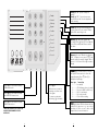
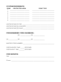
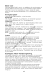
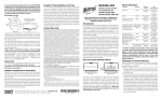
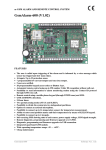
About Your Security System
Your DSC security equipment has been designed to give the greatest
possible flexibility and convenience. Read this manual carefully and have
your installer instruct you on system operation and on which features have
been implemented in your system. All users of this system should be
equally instructed in its use. Fill out the System Information page and store
this manual in a safe place for future reference.
Fire Detection
This equipment is capable of monitoring fire detection devices such as
smoke detectors and providing a warning if a fire condition is detected.
Good fire detection depends on having adequate number of detectors
placed in appropriate locations. This equipment should be installed in
accordance with applicable standards and codes. Carefully review the
Family Escape Planning guidelines in this manual.
NOTE: Your installer must enable the fire detection portion of this
equipment before it becomes functional.
Testing
To insure that your system continues to functions as intended, it is
important that you test your system weekly. See the testing procedure
elsewhere in this manual. If your system does not function properly, call
your installing company for service.
General System Operation
Your security system is made up of a DSC PC1500 or PC1550 control
panel, one or more PC1500RK keypads and various sensors and detectors.
The control panel will be mounted out of the way in a utility closet or in a
basement. The metal cabinet contains the system electronics, fuses and
stand-by battery. There is normally no reason for anyone but the installer or
serviceman to have access to the control panel. The PC1500RK keypads
have an audible indicator (buzzer), a group of zone and system status
lights and command entry keys. The keypad is used to send commands to
the system and to display the current system status. The security station(s)
will be mounted in a convenient location inside the protected premises
close to the entry/exit door(s).
The security system has several zones of area protection and each of these
zones will have one or more sensors connected to it (motion detectors,
glassbreak detectors, door contacts, etc.). When a sensor is in alarm, the
zone of alarm will be indicated on the PC1500RK (zone lights 1 through 6).
Impor
tant Notice
Important
A security system cannot prevent emergencies. It is only intended
to alert you and, if included, a monitoring station, of an emergency
situation. Security systems are generally very reliable but they may
not work under all conditions and they are not a substitute for prudent
security practices or life and property insurance. Your security
system should be installed and serviced by qualified security
professionals who should instruct you on the level of protection that
has been provided and on system operations.
1
Master Code
The 4 digit Master Code is used to arm and disarm the security system, to
program additional security codes and to change other system features.
The Master Code will be supplied to you by your installer. All keypad
entries are made by pressing one key at a time. (See Additional Codes
section)
Arming the System
Check the following items before arming the system:
Bypass Light
If the “Bypass” light is ON, insure that zones are intentionally bypassed
before arming the system (See Zone Bypassing section).
Trouble Light
If the “ Trouble” light is ON, check to see what the trouble condition is and
call for service. (See Viewing Trouble Conditions section).
Ready Light
If the “Ready” light is NOT ON, check to see that all doors and windows are
closed and that motion is stopped in areas covered by motion detectors.
The system cannot be armed unless the “Ready” light is ON indicating that
all zones are closed.
NOTE: The system may be armed with a zone bypassed or a trouble
present but your security protection will be reduced.
To Arm
Enter your 4 digit access code. As each digit is entered, the keypad
sounder will beep. If the correct access code is entered, the keypad
sounder will beep quickly and the “Armed” light will come ON.
If the access code was entered incorrectly or the “Ready” light comes ON,
the keypad buzzer will sound steadily for 2 seconds. If this occurs, press
the [#] key and re-enter your access code.
When the correct access code is entered and the “Armed” light comes ON,
exit the premises through the door indicated by your installer as the ExitEntry door.
At the end of the exit delay period, all lights, except the “Armed” light, will
go out and the system will be armed. The exit time delay can be changed
by your installer.
Auto-Bypass Option - Home-Away Arming
This feature, if selected by your installer, will allow you to arm your system
with any valid user code and the system will automatically bypass the
interior zones. The “Bypass” light will come on. If you exit within the allowed
exit time, the system will automatically activate the interior zones and the
“Bypass” light will go out. This feature is designed to save the customer
from having to manually bypass interior zones each time they wish to arm
the system and remain at home.
In residential applications where the system has been armed and the
interior zones are automatically bypassed, the interior zones can be
reactivated from a keypad that is outside the interior zone's protection area.
To reactivate the interior zones, press [ ] then [1] and the “Bypass” light
will go out.
*
2
Entry Delay Off Arming
If you wish to arm your system and eliminate the entry delay, enter [ ][9]
before your access code. The “Armed” light will flash as a reminder that the
system is armed and has no entry delay. An entry through any zone
programmed as a delay zone will create an instant alarm.
e.g. To arm without entry delay, press [ ][9][access code]
*
*
Disarming the System
Enter the premises only through the door(s) designated by your installer as
the entry door. Entering by any other door will sound an immediate alarm.
As soon as the entry door is opened, the keypad sounder will come on to
indicate that the system should be disarmed. Go to the keypad and enter
your four digit access code. If an error is made entering the code, press
the [#] key and enter your code again. As soon as the correct code is
entered, the “Armed” light will go out and the keypad sounder will silence.
The correct access code must be entered before the entry time expires.
The entry time delay may be changed by your installer. If an alarm
occurred during the period the system was armed, the “Memory” light and
the zone light of the zone that caused the alarm will flash for two minutes.
After the two minute period, the “Memory” light and zone light will stop
flashing and the panel will return to the ready state. Pressing the [#] key
during the two minute period will cancel the alarm memory display.
If a trouble is present when the panel is disarmed, the “Trouble” light will
come ON (See Viewing Trouble Conditions section to determine the source
of the trouble.) Note that troubles will not display while the system is in the
Alarm Memory Display Mode.
If you return home and find that an alarm has occurred while you were
away, it is possible that an intruder may still be on the premises. Go to a
neighbour's house and call the local police to investigate.
Quick Arm Feature
When the Quick-Arm feature is enabled, the system may be armed simply
by pressing [ ][0] instead of the 4 digit access code. This feature allows a
person to arm but not disarm the system.
Enter [ ][6][Master Code][4] to turn the Quick-Arm feature ON and OFF.
When the command is entered, the keypad buzzer will beep 3 times if
Quick-Arm is being enabled and will sound one long beep if it is being
disabled.
Press [#] to return to ready.
*
*
Door Chime Feature
The door chime feature is used, while the panel is disarmed, to provide a
tone from the keypad each time a door or window is opened or closed.
The doors and windows which will provide this indication are programmed
by your installer.
Enter [ ][6][Master Code][6] to turn the door chime feature ON and OFF.
When the command is entered, the keypad buzzer will beep 3 times if the
door chime feature is being enabled, and will sound one long beep if it is
being disabled.
Press [#] to return to Ready.
*
3
Alarm Test
Enter [ ][6][Master Code][8] for a 2-second test of the keypad lights,
keypad buzzer, battery and the bell/siren.
Press [#] to return to Ready.
*
Programming Security Codes
The Master Code
Enter [ ][5][current Master Code][1][new Master Code]
Press [#] to return to Ready.
Record your new Master Code on the System Information page in this
booklet.
*
Additional Codes
Up to 5 additional access codes (2 through 6) may be programmed. The
6th access code may be established by your installer as a One-Time use
code.
To pr
ogram a new code:
program
Enter [ ][5][Master Code][code number][new 4 digit code]
The [code number] is a single digit either 2, 3, 4, 5 or 6.
Press [#] to return to Ready.
If an access code already exists, it will be replaced by the new code.
Record your new code(s) on the System Information page in this book.
To rremove
emove a code:
Enter [ ][5][Master Code][code number][
]
The [code number] is a single digit either 2, 3, 4, 5 or 6.
Press [#] to return to ready.
Do not erase the Master Code (code number 1).
NOTE: It is recommended that the factory default Master Code [1234] not be used.
*
*
****
One-Time Use Code
The One-Time Use code is designed for entry and exit of the premises for
one occasion only. The panel must be programmed by the installer for this
option to be enabled. The 6th access code is the one-time code.
To use this code, enter your one-time code as the 6th access code using
the previously described commands. When you leave the premises, arm
your system with any access code except the newly entered one-time use
code. This one-time code is given to a person (e.g. a maid) who will enter
the premises while the system is armed and you are away.
The one-time code user enters the premises and disarms the system using
the one-time access code. Upon leaving, the same code is used to arm the
system. As soon as the system is armed, the one-time code is erased and
can not be used to re-enter the premises. A different code can be provided
each time for the one-time user.
Alarm Memory Display
If the “Memory” light is ON, an alarm has occurred during the last armed
period. The alarm memory will automatically be displayed when the system
is disarmed (See Disarming the System).
Press [ ] then [3] to display the zone which caused the alarm.
Press [#] to return to Ready.
*
4
NOTE: The alarm memory is cleared each time the panel is armed so that
any alarms showing are alarms that occurred only during the last
armed period.
If An Alarm Sounds
Fire Alarm
If your system has been installed with fire detectors and the alarm sounds
in a pulsing mode, follow your Emergency Evacuation Plan immediately.
See the guide for family escape planning elsewhere in this manual.
Intrusion Alarm
If an intrusion alarm sounds (continuous Bell/Siren), the alarm may be
silenced by entering your access code. If the alarm was unintentional, call
local authorities immediately to avoid an unnecessary response.
You can determine the source of the alarm by following the instructions in
the Alarm Viewing section of this manual. Once the source of the alarm has
been corrected, the panel can be restored to its original armed state.
Zone Bypassing
Use zone bypassing when access is needed to part of the protected area
while the system is armed. Bypassed zones will not cause an alarm. Zones
that are temporarily out of service due to damaged wiring or contacts may
be bypassed to allow system arming (partial protection) until repairs can
be made. Zones cannot be bypassed after the system is armed.
To bypass zones:
Enter [ ][1][Zone number(s) to be bypassed]
Enter zone number(s) as single digits (1-6).
As each zone is bypassed, the zone light will come ON. If a zone is
bypassed in error, press that zone number again and the zone light will go
OFF indicating that the zone is not bypassed.
Press [#] to return to Ready.
*
To recall last group of zones bypassed:
Enter [ ][1][9]
Zone lights for the last group of zones bypassed will come ON to show
which zones are bypassed. If you wish to add or delete a zone from the
group, press [#] to exit then go to zone bypass as described above.
Press [#] to return to Ready.
*
Zone Bypassing (Continued)
For security reasons, your installer may prevent the bypass command from
working on certain zones. The “Bypass” light is ON as long as ONE or more
zones are bypassed. Do not unintentionally arm the system with zones
bypassed.
Zone bypasses are automatically cancelled each time the system is
disarmed and must be re-applied before the next arming.
Viewing Trouble Conditions
The PC1500/1550 continuously monitors a number of possible trouble
conditions. If one of these trouble conditions occur, the keypad will beep
twice every 10 seconds and the keypad “Trouble” indicator will light.
5
Pressing any key on the keypad will silence the sounder but the “Trouble”
light will remain ON until the trouble condition is cleared. If you cannot
determine the cause of the trouble condition, contact your installer for
assistance.
Press [ ][2] to display the type of trouble. A zone light will come on to
indicate which type of trouble exists. Press [#] to return to Ready.
*
LIGHT
TYPE OF TROUBLE
1 .................... Low battery.
2 .................... Loss of AC power (“Trouble” light will come ON, but
..................... keypad buzzer will not sound).
3 .................... Fuse open (BELL or AUX fuse).
4 .................... Fail to communicate with monitoring station.
5 .................... Fire loop(s) trouble.
6 .................... Loss of time on system clock.
Keypad Zones
There are three keys on the keypad labelled [F] Fire, [A] Auxiliary and [P]
Panic. These keys are only functional if they have been programmed by
your installer. The installer should indicate which of these keys are
functional by placing a coloured label next to the key symbol on the
keypad door label.
[F] Fire
Holding this key down for two seconds will sound a Fire Alarm. The alarm will
sound pulsing. The keypad will sound three beeps once the panel has
accepted the alarm. An auxiliary warning device is also activated if your
installer has connected it to your system. To silence the alarm, enter a valid
access code.
[A] Auxiliary
Holding this key down for two seconds activates this function if your installer
has programmed it. There is no audible alarm and no lights on the keypad
will come on. When the panel has accepted the alarm, the keypad will sound
a series of beeps. An auxiliary warning device is activated ONLY IF connected
to your system by your installer.
[P] Panic
Holding this key down for two seconds causes a steady tone on your siren or
bell if your installer has programmed this key for audible operation. An auxiliary
warning device is also activated if your installer has connected it to your
system. Enter a valid access code to silence the alarm.
Fire Alarm Operations
Alarm
On a fire alarm, the bell/siren will sound pulsing. The digital communicator
transmission is delayed for 30 seconds. If the alarm is not acknowledged
within the 30 second delay, the communicator will transmit to the monitoring
station.
Silence
To silence the bell/siren, press the [#] key. If the alarm is silenced and the
smoke detector is not reset, the alarm will resound after 90 seconds.
6
Reset
To restore the smoke detector(s) to normal, press [ ][7]. If the detector still
has smoke in it, the alarm will resound and the sequence described above
will repeat. If the detector is clear of smoke, the system will return to
normal.
NOTE: If you suspect that the communicator has transmitted and there is
no fire condition, call the monitoring station to avoid an
unnecessary response.
If a fire condition is apparent, follow your evacuation plan
immediately. If the alarm sounds at night, evacuate
immediately.
*
Testing Your System
It is recommended that you test your system weekly.
NOTE: Perform system tests in the off-peak hours, such as early morning
or late evening.
1. Inform the monitoring station that you are testing your system.
2. Disarm the system (“Ready” light ON).
3. Perform a bell/battery test by pressing [ ][6][Master Code][8]. The
signal will sound for about 2 seconds. If a trouble occurs after the test,
press [ ][2] to view the trouble condition.
4. Activate each sensor in turn (e.g. open a door/window or walk in motion
detector areas). Observe the zone light come ON when the zone is
activated. The zone light will go OFF when the system restores to
normal (i.e. door or window closed).
5. If they are programmed for operation, press the [F], [A], and [P] keys in
turn. The [F] key will sound the bell/siren in a pulsed mode. Enter the
access code to silence the alarm. The [A] key is silent. The [P] key may
be programmed as silent or audible. If the alarm sounds, enter the
access code to silence.
6. If the panel has a zone programmed for fire, activation will cause the
alarm signal to sound in a pulsed mode.
CAUTION: Do not use an open flame or burn materials to test a smoke
detector. Contact your alarm installer for information on safe methods to
activate a smoke detector.
7. Should the system fail to operate properly, call your alarm dealer for
service.
8. When testing is complete, call and advise the monitoring station.
*
*
Maintenance
With normal use, the system requires minimum maintenance. The following
points should be observed.
1. Do not wash the keypad with a wet cloth. Light dusting with a barely
damp cloth should remove normal accumulations of dust.
2. The battery/bell test is designed to determine battery condition, however
it is recommended that the standby battery be replaced every three
years.
3. For other system devices such as passive infrared, ultrasonic or
microwave motion detectors, glassbreak detectors or smoke detectors,
consult the respective manufacturer’s literature for testing and
maintenance.
7
1
1
2
2
3
Ready light ON - System is ready for
arming.
Ready light OFF - System has an open
zone which must be closed or bypassed
before arming.
Ready
Armed
3
4
5
6
7
8
9
0
#
4
5
6
Memory
Bypass
Armed light will come ON indicating the
system is armed. To arm, ensure “Ready”
light is ON - enter 4 digit code.
Trouble
Zone 1
Zone 2
Memory light ON means an alarm has
occurred. Press [ ] then [3]. Zone light will
come ON to indicate which zone caused
the alarm.
*
Zone 3
Zone 4
Zone 5
F
A
P
F
A
P
Zone 6
Bypass light comes ON when you bypass a
zone. To bypass a zone, press [ ][1] and
then the zone(s) you wish to bypass. Enter 1
for zone 1....6 for zone 6. Press [#] to return to
Ready.
*
TEST SYSTEM WEEKLY
Trouble light is ON when there is a fault in
the system. Press any key to silence the
keypad beeping. Press [ ] then [2] to
display the trouble type .
*
Zone Light
Press [F] for 2 seconds to activate
FIRE transmission.
Press [#].....
.....
When an error is made in
entering code, then enter
code again.
Press [A] for 2 seconds to activate
an AUXILIARY transmission.
To return to ready state
after using [ ] commands.
*
Press [P] for 2 seconds to activate
PANIC transmission.
Trouble Type
1 ............. Low battery
2 ............. AC fail (buzzer does not sound)
3 ............. Fuse open (BELL or AUX fuse)
4 ............. Fail to communicate
5 ............. Fire loop(s) trouble
6 ............. Clock needs resetting
Zone light(s) when ON in the disarmed mode,
indicate an open zone. e.g. open door,
window, etc. Refer to zone chart on the
keypad door for zone information.
THESE BUTTONS WILL NOT FUNCTION
UNLESS PROGRAMMED BY YOUR
INSTALLER.
8
9
Fire Safety in the Home
Most fires occur in the home and to minimize this danger it is
recommended that a household fire safety audit be conducted and a family
escape plan be developed.
Household Fire Safety Audit
1 Are all electrical appliances and outlets in a safe condition? Check for
frayed cords, over-loaded lighting circuits, etc. If you are uncertain
about the condition of your electrical appliances or household service,
have a professional evaluation.
2 Are all flammable liquids stored safely in closed containers in a well
ventilated cool area? Cleaning with flammable liquids should be
avoided.
3 Are fire hazardous materials (matches) well out of reach of children?
4 Are furnaces and wood burning appliances properly installed, clean
and in good working order? Have a professional evaluation.
Family Escape Planning
There is often very little time between the detection of a fire and the time it
becomes deadly. It is thus very important that a family escape plan be
developed and rehearsed.
1 Every family member should participate in developing the escape plan.
2 Study the possible escape routes from each location within the house
and since many fires occur at night, special attention should be given to
the escape routes from sleeping quarters.
3 It is essential that escape from a bedroom be possible without opening
the interior door. Consider the following when making your escape
plans:
• Make sure that doors and windows that open to the outside are easily
opened. Ensure that they are not painted shut, and that their locking
mechanisms operate smoothly.
• If opening the exit or using the exit is too difficult for children, the
elderly or handicapped, plans for rescue should be developed. This
includes making sure that those who are to perform the rescue can
promptly hear the fire warning signal.
• If the exit is above the ground level, an approved fire ladder or rope
should be provided as well as training in its use.
• Exits on the ground level should be kept clear. Be sure to remove snow
from exterior patio doors in winter; outdoor furniture or equipment should
not block exits.
• The family should have a predetermined assembly point where everyone
can be accounted for; for example, across the street or at a neighbour’s
house.
• Once everyone is out of the house, call the Fire Department.
• A good plan emphasizes quick escape. Do not investigate first or attempt
to fight the fire, and do not attempt to rescue belongings or pets as this
takes up valuable time. Once outside, do not re-enter the house. Wait
for the fire department.
10
• Write the plan down and rehearse frequently, so that should an emergency
arise, everyone will know what they are to do. Revise the plan as
conditions change; for example, when there are more or fewer family
members in the home, or if there are changes to the house.
• Make sure your fire warning system is operational by conducting weekly
tests as noted elsewhere in this manual. If you are unsure about system
operation, contact your installing dealer.
• It is recommended that you contact your local fire department and request
further information on home fire safety and escape planning. If available,
have your local fire prevention officer conduct an in-house fire safety
inspection.
11
SYSTEM REFERENCE
ZONE
PROTECTED AREA
1 ____________________________
ZONE TYPE
________________________________
2
____________________________
________________________________
3
____________________________
________________________________
4
____________________________
________________________________
5
____________________________
________________________________
6
____________________________
________________________________
KEYPAD ZONE [F] FIRE ______________________________________________
KEYPAD ZONE [A] AUXILIARY _________________________________________
KEYPAD ZONE [P] PANIC _____________________________________________
PROGRAMMED CODE NUMBERS:
[2] _______________ [3] ________________
[4] _____________ [5] _______________ [6] ________________
MASTER CODE NUMBER: _____________________________________________
SYSTEM ENTRY TIME ______ SECONDS
SYSTEM EXIT TIME ________ SECONDS
FOR SERVICE:
Call: ________________________________________________________________
Phone: ______________________________________________________________
NOTICE: The Canadian Department of Communications label identifies certified equipment. This
certification means that the equipment meets certain telecommunications network protective, operational
and safety requirements. The Department does not guarantee the equipment will operate to the user’s
satisfaction.
Before installing this equipment, users should ensure that it is permissible to be connected to the facilities of
the local telecommunications company. The equipment must also be installed using an acceptable method of
connection. In some cases, the company’s inside wiring associated with a single line individual service may
be extended by means of certified connector assembly (telephone extension cord). The customer should be
aware that compliance with the above conditions may not prevent degradation of service in some situations.
Repairs to certified equipment should be made by an authorized Canadian maintenance facility designated
by the supplier. Any repairs or alterations made by the user to this equipment, or equipment malfunctions,
may give the telecommunications company cause to request the user to disconnect the equipment.
User should ensure for their own protection that the electrical ground connections of the power utility,
telephone lines and internal metallic water pipe system, if present, are connected together. This precaution
may be particularly important in rural areas.
CAUTION: Users should not attempt to make such connections themselves, but should contact the
appropriate electric inspection authority, or electrician, as appropriate.
The Load Number (LN) assigned to each terminal device denotes the percentage of the total load to be
connected to a telephone loop which is used by the device, to prevent overloading. The termination on a loop
may consist of any combination of devices subject only to the requirement that the total of the Load
Numbers of all the devices does not exceed 100.
The Load Number of this unit is 2.
AVIS: L’étiquette de l’Industrie Canada identifie le matériel homologué. Cette étiquette certifie que le matériel
est conforme à certaines normes de protection, d’exploitation et de sécurité des réseaux de télécommunications.
Industrie Canada n’assure toutefois pas que le matériel fonctionnera à la satisfaction de l’utilisateur.
Avant d’installer ce matériel, l’utilisateur doit s’assurer qu’il est permis de le raccorder aux installations de
l’entreprise locale de télécommunication. Le matériel doit également être installé en suivant une méthode acceptée
de raccordement. L’abonné ne doit pas oublier qu’il est possible que la conformité aux conditions énoncées cidessus n’empêchent pas la dégradation du service dans certaines situations.
Les réparations de matériel homologué doivent être effectuées par un centre d’entretien canadien autorisé désigné
par le fournisseur. La compagnie de télécommunications peut demander à l’utilisateur de débrancher un appareil
à la suite de réparations ou de modifications effectuées par l’utilisateur ou à cause de mauvais fonctionnement.
Pour sa propre protection, l’utilisateur doit s’assurer que tous les fils de mise à la terre de la source d’énergie
électrique, les lignes téléphoniques et les canalisations d’eau métalliques, s’il y en a, sont raccordés ensemble.
Cette précaution est particulièrement importante dans les régions rurales.
AVERTISSEMENT: L’utilisateur ne doit pas tenter de faire ces raccordements lui-même; il doit avoir recours à
un service d’inspection des installations électriques, ou à un électricien, selon le cas.
L’indice de charge (IC) assigné a chaque dispositif terminal indique, pour éviter toute surcharge, le pourcentage
de la charge totale qui peut être raccordée à un circuit téléphonique bouclé utilisé par ce dispositif. La terminaison
du circuit bouclé peut être constituée de n’importe quelle combinaison de dispositifs, pourvu que la somme des
indices de charge de l’ensemble des dispositifs ne dépasse pas 100.
L’Indice de charge de ce produit est 2.
LIMITED WARRANTY
Digital Security Controls Ltd. warrants the original
purchaser that for a period of twelve months from
the date of purchase, the product shall be free of defects in materials and workmanship under normal use.
During the warranty period, Digital Security Controls Ltd. shall, at its option, repair or replace any
defective product upon return of the product to its
factory, at no charge for labour and materials. Any
replacement and/or repaired parts are warranted for
the remainder of the original warranty or ninety (90)
days, whichever is longer. The original owner must
promptly notify Digital Security Controls Ltd. in
writing that there is defect in material or workmanship, such written notice to be received in all events
prior to expiration of the warranty period.
International Warranty
The warranty for international customers is the same
as for any customer within Canada and the United
States, with the exception that Digital Security Controls Ltd. shall not be responsible for any customs fees,
taxes, or VAT that may be due.
Warranty Procedure
To obtain service under this warranty, please return
the item(s) in question to the point of purchase. All
authorized distributors and dealers have a warranty
program. Anyone returning goods to Digital Security
Controls Ltd. must first obtain an authorization number. Digital Security Controls Ltd. will not accept any
shipment whatsoever for which prior authorization has
not been obtained.
Conditions to Void Warranty
This warranty applies only to defects in parts and workmanship relating to normal use. It does not cover:
• damage incurred in shipping or handling;
• damage caused by disaster such as fire, flood, wind,
earthquake or lightning;
• damage due to causes beyond the control of Digital
Security Controls Ltd. such as excessive voltage,
mechanical shock or water damage;
• damage caused by unauthorized attachment, alterations, modifications or foreign objects;
• damage caused by peripherals (unless such peripherals were supplied by Digital Security Controls
Ltd.);
• defects caused by failure to provide a suitable installation environment for the products;
• damage caused by use of the products for purposes
other than those for which it was designed;
• damage from improper maintenance;
• damage arising out of any other abuse, mishandling
or improper application of the products.
Digital Security Controls Ltd.’s liability for failure
to repair the product under this warranty after a reasonable number of attempts will be limited to a replacement of the product, as the exclusive remedy
for breach of warranty. Under no circumstances shall
Digital Security Controls Ltd. be liable for any special, incidental, or consequential damages based upon
breach of warranty, breach of contract, negligence,
strict liability, or any other legal theory. Such damages include, but are not limited to, loss of profits,
loss of the product or any associated equipment, cost
of capital, cost of substitute or replacement equipment, facilities or services, down time, purchaser’s
time, the claims of third parties, including customers, and injury to property.
Disclaimer of Warranties
This warranty contains the entire warranty and
shall be in lieu of any and all other warranties,
whether expressed or implied (including all implied
warranties of merchantability or fitness for a particular purpose) And of all other obligations or liabilities on the part of Digital Security Controls Ltd.
Digital Security Controls Ltd. neither assumes nor
authorizes any other person purporting to act on
its behalf to modify or to change this warranty, nor
to assume for it any other warranty or liability concerning this product.
This disclaimer of warranties and limited warranty
are governed by the laws of the province of Ontario,
Canada.
WARNING: Digital Security Controls Ltd. recommends that the entire system be completely tested on
a regular basis. However, despite frequent testing, and
due to, but not limited to, criminal tampering or electrical disruption, it is possible for this product to fail
to perform as expected.
Out of Warranty Repairs
Digital Security Controls Ltd. will at its option repair or replace out-of-warranty products which are
returned to its factory according to the following conditions. Anyone returning goods to Digital Security
Controls Ltd. must first obtain an authorization number. Digital Security Controls Ltd. will not accept
any shipment whatsoever for which prior authorization has not been obtained.
Products which Digital Security Controls Ltd. determines to be repairable will be repaired and returned.
A set fee which Digital Security Controls Ltd. has predetermined and which may be revised from time to
time, will be charged for each unit repaired.
Products which Digital Security Controls Ltd. determines not to be repairable will be replaced by the nearest equivalent product available at that time. The current market price of the replacement product will be
charged for each replacement unit.
WARNING
Please Read Carefully
Note to Installers
This warning contains vital information. As the only individual in
contact with system users, it is your responsibility to bring each
item in this warning to the attention of the users of this system.
System Failures
This system has been carefully designed to be as effective as
possible. There are circumstances, however, involving fire,
burglary, or other types of emergencies where it may not provide protection. Any alarm system of any type may be compromised deliberately or may fail to operate as expected for a
variety of reasons. Some but not all of these reasons may be:
■ Inadequate Installation
A security system must be installed properly in order to provide adequate protection. Every installation should be evaluated by a security professional to ensure that all access points
and areas are covered. Locks and latches on windows and doors
must be secure and operate as intended. Windows, doors, walls,
ceilings and other building materials must be of sufficient
strength and construction to provide the level of protection expected. A reevaluation must be done during and after any construction activity. An evaluation by the fire and/or police department is highly recommended if this service is available.
■ Criminal Knowledge
This system contains security features which were known to
be effective at the time of manufacture. It is possible for persons with criminal intent to develop techniques which reduce
the effectiveness of these features. It is important that a security system be reviewed periodically to ensure that its features
remain effective and that it be updated or replaced if it is found
that it does not provide the protection expected.
■ Access by Intruders
Intruders may enter through an unprotected access point, circumvent a sensing device, evade detection by moving through
an area of insufficient coverage, disconnect a warning device,
or interfere with or prevent the proper operation of the system.
■ Power Failure
Control units, intrusion detectors, smoke detectors and many
other security devices require an adequate power supply for
proper operation. If a device operates from batteries, it is possible for the batteries to fail. Even if the batteries have not
failed, they must be charged, in good condition and installed
correctly. If a device operates only by AC power, any interruption, however brief, will render that device inoperative while it
does not have power. Power interruptions of any length are
often accompanied by voltage fluctuations which may damage
electronic equipment such as a security system. After a power
interruption has occurred, immediately conduct a complete
system test to ensure that the system operates as intended.
■ Failure of Replaceable Batteries
This system’s wireless transmitters have been designed to provide several years of battery life under normal conditions. The
expected battery life is a function of the device environment,
usage and type. Ambient conditions such as high humidity,
high or low temperatures, or large temperature fluctuations may
reduce the expected battery life. While each transmitting device has a low battery monitor which identifies when the batteries need to be replaced, this monitor may fail to operate as
expected. Regular testing and maintenance will keep the system in good operating condition.
■ Compromise of Radio Frequency
(Wireless) Devices
Signals may not reach the receiver under all circumstances which
could include metal objects placed on or near the radio path or
deliberate jamming or other inadvertent radio signal interference.
■ System Users
A user may not be able to operate a panic or emergency switch
possibly due to permanent or temporary physical disability,
inability to reach the device in time, or unfamiliarity with the
correct operation. It is important that all system users be trained
in the correct operation of the alarm system and that they know
how to respond when the system indicates an alarm.
■ Smoke Detectors
Smoke detectors that are a part of this system may not properly
alert occupants of a fire for a number of reasons, some of which
follow. The smoke detectors may have been improperly installed
or positioned. Smoke may not be able to reach the smoke detectors, such as when the fire is in a chimney, walls or roofs, or on
the other side of closed doors. Smoke detectors may not detect
smoke from fires on another level of the residence or building.
Every fire is different in the amount of smoke produced and
the rate of burning. Smoke detectors cannot sense all types of
fires equally well. Smoke detectors may not provide timely
warning of fires caused by carelessness or safety hazards such
as smoking in bed, violent explosions, escaping gas, improper
storage of flammable materials, overloaded electrical circuits,
children playing with matches or arson.
Even if the smoke detector operates as intended, there may be
circumstances when there is insufficient warning to allow all
occupants to escape in time to avoid injury or death.
■ Motion Detectors
Motion detectors can only detect motion within the designated
areas as shown in their respective installation instructions. They
cannot discriminate between intruders and intended occupants.
Motion detectors do not provide volumetric area protection.
They have multiple beams of detection and motion can only be
detected in unobstructed areas covered by these beams. They
cannot detect motion which occurs behind walls, ceilings, floor,
closed doors, glass partitions, glass doors or windows. Any
type of tampering whether intentional or unintentional such as
masking, painting, or spraying of any material on the lenses,
mirrors, windows or any other part of the detection system
will impair its proper operation.
Passive infrared motion detectors operate by sensing changes in
temperature. However their effectiveness can be reduced when
the ambient temperature rises near or above body temperature
or if there are intentional or unintentional sources of heat in or
near the detection area. Some of these heat sources could be
heaters, radiators, stoves, barbeques, fireplaces, sunlight, steam
vents, lighting and so on.
■ Warning Devices
Warning devices such as sirens, bells, horns, or strobes may
not warn people or waken someone sleeping if there is an intervening wall or door. If warning devices are located on a
different level of the residence or premise, then it is less likely
that the occupants will be alerted or awakened. Audible warning devices may be interfered with by other noise sources such
as stereos, radios, televisions, air conditioners or other appliances, or passing traffic. Audible warning devices, however
loud, may not be heard by a hearing-impaired person.
■ Telephone Lines
If telephone lines are used to transmit alarms, they may be out of
service or busy for certain periods of time. Also an intruder may
cut the telephone line or defeat its operation by more sophisticated means which may be difficult to detect.
■ Insufficient Time
There may be circumstances when the system will operate as
intended, yet the occupants will not be protected from the emergency due to their inability to respond to the warnings in a
timely manner. If the system is monitored, the response may
not occur in time to protect the occupants or their belongings.
■ Component Failure
Although every effort has been made to make this system as
reliable as possible, the system may fail to function as intended
due to the failure of a component.
■ Inadequate Testing
Most problems that would prevent an alarm system from operating as intended can be found by regular testing and maintenance. The complete system should be tested weekly and immediately after a break-in, an attempted break-in, a fire, a storm,
an earthquake, an accident, or any kind of construction activity inside or outside the premises. The testing should include
all sensing devices, keypads, consoles, alarm indicating devices and any other operational devices that are part of the
system.
■ Security and Insurance
Regardless of its capabilities, an alarm system is not a substitute for property or life insurance. An alarm system also is not
a substitute for property owners, renters, or other occupants to
act prudently to prevent or minimize the harmful effects of an
emergency situation.
Instruction
Manual
PC15OO/PC155O
© 1997 Digital Security Controls Ltd.
1645 Flint Road, Downsview, Ontario, Canada M3J 2J6
Printed in Canada 29000203 R3
• W A R N I N G •
This manual contains information on
limitations regarding product use and
function and information on the limitations
as to liability of the manufacturer. The entire
manual should be carefully read.