1
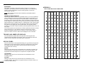
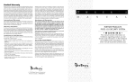
Jan 11, 1993
Software Version 1.3
Instruction
Manual
© 1993 Digital Security Controls Ltd.
Toronto, Canada • www.dsc.com
Printed in Canada 29000226 R0
PC4OOO SECURITY SYSTEM
INTRODUCTION
The LCD-4500 keypad provides easy to understand English language
information about the status of your security system and makes daily operation
simple by prompting the user through each operation.
The keypad provides audible feedback each time a key is pressed and with
unique audible sequences it signals troubles and the correct or incorrect entry
of information.
ABOUT YOUR SECURITY SYSTEM
Your DSC security equipment has been designed to give you the greatest
possible flexibility and convenience. The LCD-4500 keypad will guide you
through each operation with English language prompts. Read this manual
carefully and have your installer instruct you on system operation and on which
features have been implemented on your system.
FIRE DETECTION
This equipment is capable of monitoring fire detection devices such as smoke
detectors and providing a warning alarm if a fire condition is detected. Good fire
detection depends on having adequate numbers of fire detectors placed in
appropriate locations. This equipment should be installed in accordance with
N.F.P.A. standard #74 (N.F.P.A. Batterymarch Park, Quincey MA 02269).
Carefully review the Family Escape Planning guidelines in this manual.
NOTE: Your installer must enable the fire detection portion of this equipment
before it becomes functional.
Important Note
A security system cannot prevent emergencies. It is only intended to alert you
and, if included, a monitoring station of an emergency situation. Security
systems are generally very reliable but they may not work under all conditions
and they are not a substitute for prudent security practices or life and property
insurance. Your security system should be installed and serviced by qualified
security professionals who should instruct you on the level of protection that has
been provided and on system operation.
1
MONITORING
This system is capable of transmitting alarms, troubles, and emergency
information over telephone lines to a monitoring station. If you inadvertently
initiate an alarm, immediately call the monitoring station to prevent an
unnecessary response.
NOTE: The monitoring function must be enabled by the installer before it
becomes functional.
GENERAL SYSTEM OPERATION
Your security system is made up of a PC4000 and one or more LCD-4500 and
various detectors and sensors. The DSC control panel will be mounted out of
the way in a utility room or basement. The metal cabinet contains the system
electronics, fuses and stand-by battery. There is normally no reason for anyone
but the installer or service person to have access to the control panel. The LCD4500 keypads have an audible indicator, an alphanumeric LCD, (Liquid Crystal
Display), and command entry keys. The keypad is used to send commands to
the system and to display the current system status. The keypad(s) will be
mounted in convenient locations inside the protected premises close to the exitentry doors.
The security system has several zones or areas of protection and each of these
zones will have one or more detection sensors connected to it (motion
detectors, glassbreak detectors, door contacts or shock sensors). When a
sensor is in alarm, the zone in alarm will be displayed on the LCD-4500.
APPENDIX A
LIST OF AVAILABLE ASCII CHARACTERS
032
048
064
080
096
112
160
176
192
208
224
240
033
049
065
081
097
113
161
177
193
209
225
241
034
050
066
082
098
114
162
178
194
210
226
242
035
051
067
083
099
115
163
179
195
211
227
243
036
052
068
084
100
116
164
180
196
212
228
244
037
053
069
085
101
117
165
181
197
213
229
245
038
054
070
086
102
118
166
182
198
214
230
246
039
055
071
087
103
119
167
183
199
215
231
247
040
056
072
088
104
120
168
184
200
216
232
248
041
057
073
089
105
121
169
185
201
217
233
249
042
058
074
090
106
122
170
186
202
218
234
250
043
059
075
091
107
123
171
187
203
219
235
251
044
060
076
092
108
124
172
188
204
220
236
252
045
061
077
093
109
125
173
189
205
221
237
253
046
062
078
094
110
126
174
190
206
222
238
254
047
063
079
095
111
127
175
191
207
223
239
255
TROUBLE AND ARMED LED DISPLAYS
The LCD-4500 has a yellow LED on the right side of the keypad which
represents the trouble status of the panel. There is a red LED just below the
yellow one which represents the armed status of the panel.
KEYPAD ZONES
There are three keys on the keypad labeled [F] Fire, [A] Auxiliary and [P] Panic.
These keys are only functional if they have been programmed by the installer.
The installer should indicate which of these keys are active by placing a
colored label next to the key.
[F] FIRE
Holding this key down for two seconds will sound a fire alarm. The alarm will
sound pulsing and a transmission will be sent to the monitoring station. The
keypad will sound three beeps once the panel has accepted the alarm.
[A] AUXILIARY
Holding this key down for two seconds will send a transmission to the
monitoring station.
[P] PANIC
Holding this key down for two seconds will send a transmission to the
monitoring station. The installer can program this key to sound the alarm or to
2 transmit the alarm silently.
MAINTENANCE
Close all protected doors and windows and stop movement in areas covered by
motion detectors.
1. Do not wash the keypad with a wet cloth. Light dusting with a barely damp
cloth should remove normal accumulations of dust.
The “Enter Code to Arm System” message should be on the LCD display. The
system cannot be armed unless the “Enter Code to Arm System” or “Secure
System or Enter Code...” message is displayed.
2. The battery/bell test is designed to determine battery condition, however it is
recommended that the stand-by batteries be replaced every three years.
3. For other system devices such as smoke detectors, passive infrared,
ultrasonic or microwave motion detectors or glassbreak detectors, consult the
respective manufacturer’s literature for testing and maintenance.
LIMITED WARRANTY
Digital Security Controls Ltd. warrants that for a period of twelve months from the
date of purchase, the product shall be free of defects in materials and
workmanship under normal use and that in fulfillment of any breach of such
warranty, Digital Security Controls Ltd. shall, at its option, repair or replace the
defective equipment upon return of the equipment to its factory. This warranty
applies only to defects in parts and workmanship and not to damage incurred in
shipping or handling, or damage due to causes beyond the control of Digital
Security Controls Ltd. such as lightning, excessive voltage, mechanical shock,
water damage, or damage arising out of abuse, alteration or improper
application of the equipment.
The foregoing warranty shall apply only to the original buyer, and is and shall
be in lieu of any and all other warranties, whether expressed or implied and of
all other obligations or liabilities on the part of Digital Security Controls Ltd. This
warranty contains the entire warranty. Digital Security Controls Ltd. neither
assumes, nor authorizes any other person purporting to act on its behalf to
modify or to change this warranty, nor to assume for it any other warranty or
liability concerning this product.
In no event shall Digital Security Controls Ltd. be liable for any direct or indirect
or consequential damages, loss of anticipated profits, loss of time or any other
losses incurred by the buyer in connection with the purchase, installation or
operation or failure of this product.
WARNING
Digital Security Controls Ltd. recommends that the entire system be completely
tested on a regular basis. However, despite frequent testing, and due to, but not
limited to, criminal tampering or electrical disruption, it is possible for this
product to fail to perform as expected.
10
ARMING
With normal use, the system requires minimum maintenance. The following
points should be observed.
Enter a [4 Digit Security Code]. As each digit is entered the keypad will beep.
• If the security code was entered incorrectly, the keypad will beep steadily for
2 seconds.
• If the code was entered correctly but the system was not secure due to an
open zone, the keypad will beep quickly followed by a steady tone.
• When the correct code is entered, the “Exit delay in Progress” message will
be displayed and the keypad will beep quickly.
A timer will appear in the right side of the display indicating the remaining time
in the exit delay. Exit the premises through the designated exit-entry door. At the
end of the allowed exit time the message on the keypad will change to “Enter
Code to Disarm System”.
DISARMING
Enter the premises through the designated exit-entry door. The keypad buzzer
will be on. Go to the keypad and enter the [4 digit security code]. If an error is
made in entering the code, press the [#] key and enter the code again. The
“Armed” light will go out and the keypad buzzer will stop. The correct security
code must be entered before the allowed entry time expires. If an alarm
occurred while the panel was armed, the “View Memory” message will be on
the display with the zone name for the zone that caused the alarm. The display
will keep those messages on for two minutes or until the [#] key is pressed to
return the panel to the normal arm-disarm mode.
AUTO-BYPASS/HOME-AWAY ARMING
If a correct security code is entered and you do not exit the premises through a
designated exit-entry door, the system will, at the end of the Exit delay time, arm
with interior zones automatically bypassed if those interior zones have been
programmed as “Home-away” zones. These zones will remain bypassed until
[✱][1] is entered to reactivate bypassed home-away zones.
This is a convenience feature for someone who wishes to remain on the
premises with the system armed. That person does not have to manually bypass
the home-away zones.
To reactivate the Home-away zones that have been automatically bypassed,
press [✱][1]. This command is a quick method of fully arming the system in
residential applications before going to bed.
3
FIRE SAFETY IN THE HOME
ZONE BYPASSING
[✱
✱]+[1]
A bypassed zone will not cause an alarm. If a zone is bypassed the panel may
be armed even if the zone is open. Use zone bypassing when access is needed
to part of the protected area. Also, damaged wiring or contacts on a zone may
be temporarily bypassed until repairs can be made so that the panel can be
armed.
To bypass zones, enter [✱][1]. An access code may be required if the installer
has enabled that option. A menu will appear.
[0] Bypass Zones - This selection takes you immediately to bypassing zones.
Use the [<][>] to select the zones to be bypassed and press the [✱] key to
select the zone. A “✱” will appear beside the zone label to indicate the zone
will be bypassed when the partition is armed.
A zone search routine allows the user to find the desired zone to bypass by
entering in the first letter of the zone to search for, and pressing one of the [<][>]
keys. The [<] key will search for the first zone on the partition that begins with
the letter selected. The [>] key will search for the last zone on the partition that
begins with the letter selected.
The letters of the alphabet have been divided up among the 1-9 number keys on
the keypad.
1
2
3
ABC
DEF
GHI
4
5
6
JKL
MNO
PQR
7
8
9
STU
VWX
YZ
Most fires occur in the home and to minimize this danger it is recommended that
a household fire safety audit be conducted and a family escape plan be
developed.
HOUSEHOLD FIRE SAFETY AUDIT
1. Are all electrical appliances and outlets in a safe condition e.g. frayed cords,
over-loaded lighting circuits? If you are uncertain about the condition of your
electrical appliances or household service, have a professional evaluation.
2. Are all flammable liquids stored safely in closed containers in a well
ventilated cool area? Cleaning with flammable liquids should be avoided.
3. Are fire hazardous materials (matches) well out of reach of children?
4. Are furnaces and wood burning appliances properly installed, clean and in
good working order? Have a professional evaluation.
FAMILY ESCAPE PLANNING
There is often very little time between the detection of a fire and the time it
becomes deadly. It is thus very important that a family escape plan be
developed and rehearsed.
1. Every family member should participate in developing the escape plan.
2. Study the possible escape routes from each location within the house and
since many fires occur at night, special attention should be given to the escape
routes from sleeping quarters.
3. It is essential that escape from a bedroom be possible without opening the
interior door. To facilitate such an escape:
■ Make sure that doors and/or windows that open to the outside are easily opened. e.g. not painted
shut.
■ Simply making the exit may be too difficult for children, the elderly or handicapped, plans for rescue
should be developed. This includes making sure that those who are to perform the rescue can
promptly hear the fire warning signal.
■ If the exit means is above the ground level, an approved fire ladder or rope should be provided as
[1] Clear Bypasses - Removes all bypasses from all the zones in your partition
and then takes you to bypassing zones. None of the zones will have a “✱”
beside them.
[2] Recall Bypasses - Selecting this will bypass all the same zones that were
selected the last time zones were bypassed. This is for users that are always
bypassing the same zones.
[3] Previous Menu - takes you back to the “Enter Code to Arm System”.
When the PC4000 is programmed, the ability to bypass certain zones may have
been eliminated by the installer. In this case, the “✱” message for those zones
will not come on in response to the bypass command. The [✱][1] command
should be used to see which zones are bypassed so that zones are not
unintentionally bypassed. Zone bypasses are automatically cancelled when the
panel is disarmed.
NOTE: At no time can any armed zone be bypassed.
4
While the system is disarmed, bypassing can be used to temporarily silence the
door chime feature on a zone. Simply bypass the zone that the door chime
feature enabled. The keypad will no longer beep when the zone is opened. Be
sure to clear all bypasses before arming, to ensure no zones are unintentionally
bypassed.
well as training in its use.
■ Exits on the ground level should be kept clear, e.g. remove snow from exterior patio doors.
■ The family should have a predetermined assembly point where everyone can be accounted for, e.g.
across the street or at a neighbours.
■ Once everyone is out of the house call the Fire Department.
■ A good plan emphasizes quick escape. Do not investigate first or attempt to fight the fire and do
not attempt to rescue valuables or pets as this takes up valuable time. Once outside, do not re-enter
the house. Wait for the fire department.
■ Write the plan down and rehearse frequently so that should an emergency arise, everyone will know
what they are to do. Revise the plan as conditions change, e.g. more or fewer family member or
changes to the house.
■ Make sure your fire warning system is operational by conducting weekly tests as noted elsewhere in
this manual. If you are unsure about system operation, contact your installing dealer.
■ It is recommended that you contact your local fire department and request
further information on home fire safety and escape planning. If available, have your local fire prevention
officer conduct an in-house fire safety inspection.
9
VIEW PARTITIONS
[✱]+[6]+[ACCESS CODE]+[8]
This function will allow the user to view the status of other partitions that their
access code has been enabled for. For example, if an access code has
been enabled for partitions 1, 2 and 5, they can only view the status of these
partitions.
To view the partitions status, press the [<] or [>] key to toggle through the
partitions. The partition labels will be displayed along with a letter to the far
right. The letter shows the status of that partition.
A means the partition is Armed
R means the partition is secure and Ready to be armed
N means Not ready to be armed because zones are not secure.
This function must be enabled by the installer for the user to be able to enter
this section. If the installer does not enable this section, you will hear an
error tone when selecting this section.
INSTALLERS’ PROGRAMMING COMMANDS
[✱]+[8]+[INSTALLER’S CODE]
This command is used by the installer to program the PC4000.
“AT-HOME” ARMING
[✱]+[9]+[ACCESS CODE]
Entering [✱][9] before the arming code, arms the panel without any entry
delay on the delay zones and bypasses zones that are defined as “Homeaway”. This command is used for arming the system while at home. Once
the panel is Armed in this mode, using [✱][1] will remove the bypass from
those zones defined as “Home-away” if they have NOT been manually
bypassed. The [✱][1] command, as used here, only removes the bypass
from zones that were automatically bypassed with the [✱][9] command.
QUICK ARM
[✱]+[0]
Entering [✱][0] is accepted as a valid arming code when the “Quick Arm”
feature is activated. This command is often used when individuals are
required to arm the system but not disarm it. This could be used with home
visitors in the case of a residential alarm or junior employees and
maintenance staff in the case of a commercial alarm. See instructions in the
“[✱][6] User Functions Command” section for activating the “Quick Arm”
feature.
QUICK EXIT
[✱]+[0] WHEN ARMED
Entering [✱][0] when the partition is armed will allow the user 2 minutes to
exit the premises through any delay zone without altering the status of the
system if the “Quick Exit” feature is enabled. After [✱][0] is entered into an
armed system, one and only one delay zone may be tripped. Any additional
activity on any other active zone will cause that zone to begin its alarm
sequence.
8
TROUBLE DISPLAY
[✱]+[2]
The PC4000 continuously monitors a number of possible trouble conditions. If
one of these conditions occurs, the keypad “TROUBLE” indicator will light and
the audible indication will sound (two short beeps every 10 seconds). When the
[#] key is pressed the audible indication will stop on that partition, but the
trouble indicator light will remain ON until the trouble is cleared. Trouble
conditions can also be transmitted to the monitoring station. Press the [✱] then
[2] keys to display the trouble conditions.
■ Low stand-by battery
■ Loss of time on internal clock
■ AC power failure
■ COMBUS communications fault
■ Auxiliary supply trouble
■ COMBUS low voltage
■ Telephone line trouble
■ Internal fault
■ 4204 Battery TBL
■ Bell circuit failure
■ 4204 AC Trouble
■ Smoke detector loop trouble
■ 4204 Aux Trouble
■ Unsuccessful communication
attempt with monitoring station
Press [#] to return to “READY”.
Low Battery...A battery trouble will be displayed if the battery is low, disconnected or
the battery fuse fails.
AC Power Failure...There is no audible annunciation on AC power failure. The system
“Trouble” light will come ON but the audible indication will not sound until there is a low
battery condition.
Auxiliary Supply Trouble...A trouble is generated if the auxiliary fuse fails.
Telephone Line Trouble...A telephone line trouble is generated when the line voltage
drops below 3 volts for more than 30 seconds. A keypad trouble is generated when the
system is disarmed and if selected, a local alarm sounds when the panel is armed.
Unsuccessful Communication...If the digital communicator is unsuccessful in
communicating with the monitoring station after 10 attempts, a Fail to Communicate
trouble is generated. If a later attempt to communicate is successful the trouble is
cleared.
Bell Circuit Failure...If the bell fuse opens or the bell circuit is open, a keypad trouble
and a Bell Circuit trouble transmission are generated.
Smoke Detector Loop Trouble...If a FIRE loop is open circuit, a keypad trouble and a
Fire Loop trouble transmission are generated. A trouble on the FIRE loop will
unconditionally initiate an audible indication on the keypad. This means that even if any
other previous trouble has been silenced, a FIRE loop trouble will restart the keypad
buzzer.
Loss of Internal Time...When the PC4000 is powered up, the internal time of day clock
needs to be set to the correct time. Programming the time will clear this trouble.
COMBUS Communications Fault...Contact installer.
COMBUS Low Voltage...Contact installer.
Internal Fault...Contact installer.
4204 Battery TBL...If any PC4204 relay output module’s battery drops below 11.3 volts,
a battery trouble is generated.
The battery voltage is checked once every 4 minutes. So the battery trouble may not
restore instantly when the battery voltage is restored.
4204 AC Trouble...If any PC4204 relay output module loses incoming AC power, the
keypad trouble light will indicate a 4204 AC trouble. But there will be no audible
annunciation until there is also a low battery condition.
4204 AUX Trouble...If the Aux fuse on any PC4204 relay module should open or if the
Aux supply is overloaded, a 4204 Aux trouble is generated.
5
ALARM MEMORY DISPLAY
[✱]+[3]
Press [✱] then [3] to enter the alarm memory mode. Any alarm caused during
the last armed period will be displayed. The “Alarm Memory” message will only
be displayed when an alarm occurred during the last armed period.
Press [#] to return to “READY”.
USER FUNCTIONS COMMAND
[✱]+[6]+[ACCESS CODE]
Enter [✱][6][Access Code] and then use the [<][>] keys to display the items of
the function menu. Press [✱] to select an item.
[0] Quick Arm
[1] Quick Exit
[2] Auto Arm Control [3] Keypad Setup
[4] Bell/Comm Test [5] Door Chime [6] Spec. Messages [7] User Call Up
[8] View Partitions
Item [0], [1], [5] and [6] turn on and off various functions. To enable or disable
these functions, press the [✱] key to toggle “Y ”or “N” on the keypad.
Y - The function is enabled
N - The function is disabled
KEYPAD SETUP
[ ]+[6]+[ACCESS CODE]+[3]
This function allows the user to adjust the backlighting and contrast of the LCD4500 keypad. When this function is selected, the Keypad Setup menu will appear
on the keypad.
■ Bright Control adjusts the level of backlighting on the LCD display and the
backlighting on the keys.
■ Contrast Control adjusts the contrast of the lettering on the LCD display.
Use the [<][>] keys to toggle through the eight different settings, and press [✱] to
select the level of preference.
QUICK ARM
[✱]+[6]+[ACCESS CODE]+[0]
The “Quick Arm” feature is enabled by toggling to “Y” on the keypad. When
enabled the panel can be armed by entering [✱][0]. One time use access
codes should not be used with the quick arm feature. The one time use code is
only erased when used to arm.
BELL/COMM TEST
[✱]+[6]+[ACCESS CODE]+[4]
This option allows the end user to test the system. The bell’s and keypad buzzer’s
are activated for two seconds and a test code transmission will send to the
monitoring station.
QUICK EXIT
[✱]+[6]+[ACCESS CODE]+[1]
The “Quick Exit” function is enabled by toggling to “Y” on the keypad. When
enabled the user can exit through any delay zone without altering the status of
the system, by entering [✱][0] on the keypad.
DOOR CHIME
[✱]+[6]+[ACCESS CODE]+[5]
The Door Chime feature is enabled or disabled by pressing the [✱] key to toggle
from “N” to “Y” or “Y” to “N”. When the chime zone is activated, the keypad will
beep quickly 5 times. The “Beeping” on doors can be eliminated temporarily by
using zone bypass, only when the panel is disarmed.
AUTO ARM CONTROL
[✱]+[6]+[ACCESS CODE]+[2]
This function must be enabled by the installer, or an error tone will sound when
this section is entered.
The PC4000 can be programmed to arm a partition at the same time each day,
by enabling the Auto Arm function and programming the Auto Arm time.
At the selected Auto Arm time, the system will give a pre-alert. The keypad
begins to sound and the Bell/Siren will pulse once every 10 seconds to alert
anyone on the premises that the system is about to arm. The Bell/Siren pulse
can be programmed by the installer to be silent.
The keypad will sound for one minute before Auto Arming unless the Auto Arm
is aborted. To abort the Auto Arm and silence the keypad press any key during
the pre-alert. The Auto Arm will be attempted at the same time the following day.
The PC4000 can be programmed to require a code to be entered for a user to
abort the Auto Arm by the installer.
Upon selecting the Auto Arm Control function, the Auto Arm Control menu will
appear on the LCD keypad.
[0] Auto Arm
[1] Auto Arm Time
6
Auto Arm toggles “Y” or “N” to enable or disable the Auto Arm function.
Auto Arm time is the time the partition will automatically arm itself every day.
NOTE: The Auto Arm time is a 24 hour clock and times must be entered as two
digit numbers.
E.g. HH - 01, 02,.....10,11,.....23,24
MM - 00, 01,.....35,36.....58,59
Enter 4 digits representing the time in hours and minutes (HH:MM) based on 24
hour or military time. Always enter a leading zero where only one digit is
required, 8:05 am would be entered as 0805, 1:30 pm would be entered as 1330.
SPEC. MESSAGES
[✱]+[6]+[ACCESS CODE]+[6]
This function enables two special event messages to be displayed when one of
the special events occurs.
The first message is “Fail to Arm”. It will be displayed if the user is unable to arm
the partition after entering a valid code (E.g. Because of activity on the zones.).
The second message is “Alarm When Armed”. It will be displayed if an alarm
occurred during the previous armed period.
The messages are programmed by the installer.
USER CALL UP
[✱]+[6]+[ACCESS CODE]+[7]
This function must be enabled by the installer. When selected, the panel will call
the downloading computer. The downloading computer must be waiting for the
panel to call before downloading can be performed.
Only use this function upon request from the installer.
7
VIEW PARTITIONS
[✱]+[6]+[ACCESS CODE]+[8]
This function will allow the user to view the status of other partitions that their
access code has been enabled for. For example, if an access code has
been enabled for partitions 1, 2 and 5, they can only view the status of these
partitions.
To view the partitions status, press the [<] or [>] key to toggle through the
partitions. The partition labels will be displayed along with a letter to the far
right. The letter shows the status of that partition.
A means the partition is Armed
R means the partition is secure and Ready to be armed
N means Not ready to be armed because zones are not secure.
This function must be enabled by the installer for the user to be able to enter
this section. If the installer does not enable this section, you will hear an
error tone when selecting this section.
INSTALLERS’ PROGRAMMING COMMANDS
[✱]+[8]+[INSTALLER’S CODE]
This command is used by the installer to program the PC4000.
“AT-HOME” ARMING
[✱]+[9]+[ACCESS CODE]
Entering [✱][9] before the arming code, arms the panel without any entry
delay on the delay zones and bypasses zones that are defined as “Homeaway”. This command is used for arming the system while at home. Once
the panel is Armed in this mode, using [✱][1] will remove the bypass from
those zones defined as “Home-away” if they have NOT been manually
bypassed. The [✱][1] command, as used here, only removes the bypass
from zones that were automatically bypassed with the [✱][9] command.
QUICK ARM
[✱]+[0]
Entering [✱][0] is accepted as a valid arming code when the “Quick Arm”
feature is activated. This command is often used when individuals are
required to arm the system but not disarm it. This could be used with home
visitors in the case of a residential alarm or junior employees and
maintenance staff in the case of a commercial alarm. See instructions in the
“[✱][6] User Functions Command” section for activating the “Quick Arm”
feature.
QUICK EXIT
[✱]+[0] WHEN ARMED
Entering [✱][0] when the partition is armed will allow the user 2 minutes to
exit the premises through any delay zone without altering the status of the
system if the “Quick Exit” feature is enabled. After [✱][0] is entered into an
armed system, one and only one delay zone may be tripped. Any additional
activity on any other active zone will cause that zone to begin its alarm
sequence.
8
TROUBLE DISPLAY
[✱]+[2]
The PC4000 continuously monitors a number of possible trouble conditions. If
one of these conditions occurs, the keypad “TROUBLE” indicator will light and
the audible indication will sound (two short beeps every 10 seconds). When the
[#] key is pressed the audible indication will stop on that partition, but the
trouble indicator light will remain ON until the trouble is cleared. Trouble
conditions can also be transmitted to the monitoring station. Press the [✱] then
[2] keys to display the trouble conditions.
■ Low stand-by battery
■ Loss of time on internal clock
■ AC power failure
■ COMBUS communications fault
■ Auxiliary supply trouble
■ COMBUS low voltage
■ Telephone line trouble
■ Internal fault
■ 4204 Battery TBL
■ Bell circuit failure
■ 4204 AC Trouble
■ Smoke detector loop trouble
■ 4204 Aux Trouble
■ Unsuccessful communication
attempt with monitoring station
Press [#] to return to “READY”.
Low Battery...A battery trouble will be displayed if the battery is low, disconnected or
the battery fuse fails.
AC Power Failure...There is no audible annunciation on AC power failure. The system
“Trouble” light will come ON but the audible indication will not sound until there is a low
battery condition.
Auxiliary Supply Trouble...A trouble is generated if the auxiliary fuse fails.
Telephone Line Trouble...A telephone line trouble is generated when the line voltage
drops below 3 volts for more than 30 seconds. A keypad trouble is generated when the
system is disarmed and if selected, a local alarm sounds when the panel is armed.
Unsuccessful Communication...If the digital communicator is unsuccessful in
communicating with the monitoring station after 10 attempts, a Fail to Communicate
trouble is generated. If a later attempt to communicate is successful the trouble is
cleared.
Bell Circuit Failure...If the bell fuse opens or the bell circuit is open, a keypad trouble
and a Bell Circuit trouble transmission are generated.
Smoke Detector Loop Trouble...If a FIRE loop is open circuit, a keypad trouble and a
Fire Loop trouble transmission are generated. A trouble on the FIRE loop will
unconditionally initiate an audible indication on the keypad. This means that even if any
other previous trouble has been silenced, a FIRE loop trouble will restart the keypad
buzzer.
Loss of Internal Time...When the PC4000 is powered up, the internal time of day clock
needs to be set to the correct time. Programming the time will clear this trouble.
COMBUS Communications Fault...Contact installer.
COMBUS Low Voltage...Contact installer.
Internal Fault...Contact installer.
4204 Battery TBL...If any PC4204 relay output module’s battery drops below 11.3 volts,
a battery trouble is generated.
The battery voltage is checked once every 4 minutes. So the battery trouble may not
restore instantly when the battery voltage is restored.
4204 AC Trouble...If any PC4204 relay output module loses incoming AC power, the
keypad trouble light will indicate a 4204 AC trouble. But there will be no audible
annunciation until there is also a low battery condition.
4204 AUX Trouble...If the Aux fuse on any PC4204 relay module should open or if the
Aux supply is overloaded, a 4204 Aux trouble is generated.
5
FIRE SAFETY IN THE HOME
ZONE BYPASSING
[✱
✱]+[1]
A bypassed zone will not cause an alarm. If a zone is bypassed the panel may
be armed even if the zone is open. Use zone bypassing when access is needed
to part of the protected area. Also, damaged wiring or contacts on a zone may
be temporarily bypassed until repairs can be made so that the panel can be
armed.
To bypass zones, enter [✱][1]. An access code may be required if the installer
has enabled that option. A menu will appear.
[0] Bypass Zones - This selection takes you immediately to bypassing zones.
Use the [<][>] to select the zones to be bypassed and press the [✱] key to
select the zone. A “✱” will appear beside the zone label to indicate the zone
will be bypassed when the partition is armed.
A zone search routine allows the user to find the desired zone to bypass by
entering in the first letter of the zone to search for, and pressing one of the [<][>]
keys. The [<] key will search for the first zone on the partition that begins with
the letter selected. The [>] key will search for the last zone on the partition that
begins with the letter selected.
The letters of the alphabet have been divided up among the 1-9 number keys on
the keypad.
1
2
3
ABC
DEF
GHI
4
5
6
JKL
MNO
PQR
7
8
9
STU
VWX
YZ
Most fires occur in the home and to minimize this danger it is recommended that
a household fire safety audit be conducted and a family escape plan be
developed.
HOUSEHOLD FIRE SAFETY AUDIT
1. Are all electrical appliances and outlets in a safe condition e.g. frayed cords,
over-loaded lighting circuits? If you are uncertain about the condition of your
electrical appliances or household service, have a professional evaluation.
2. Are all flammable liquids stored safely in closed containers in a well
ventilated cool area? Cleaning with flammable liquids should be avoided.
3. Are fire hazardous materials (matches) well out of reach of children?
4. Are furnaces and wood burning appliances properly installed, clean and in
good working order? Have a professional evaluation.
FAMILY ESCAPE PLANNING
There is often very little time between the detection of a fire and the time it
becomes deadly. It is thus very important that a family escape plan be
developed and rehearsed.
1. Every family member should participate in developing the escape plan.
2. Study the possible escape routes from each location within the house and
since many fires occur at night, special attention should be given to the escape
routes from sleeping quarters.
3. It is essential that escape from a bedroom be possible without opening the
interior door. To facilitate such an escape:
■ Make sure that doors and/or windows that open to the outside are easily opened. e.g. not painted
shut.
■ Simply making the exit may be too difficult for children, the elderly or handicapped, plans for rescue
should be developed. This includes making sure that those who are to perform the rescue can
promptly hear the fire warning signal.
■ If the exit means is above the ground level, an approved fire ladder or rope should be provided as
[1] Clear Bypasses - Removes all bypasses from all the zones in your partition
and then takes you to bypassing zones. None of the zones will have a “✱”
beside them.
[2] Recall Bypasses - Selecting this will bypass all the same zones that were
selected the last time zones were bypassed. This is for users that are always
bypassing the same zones.
[3] Previous Menu - takes you back to the “Enter Code to Arm System”.
When the PC4000 is programmed, the ability to bypass certain zones may have
been eliminated by the installer. In this case, the “✱” message for those zones
will not come on in response to the bypass command. The [✱][1] command
should be used to see which zones are bypassed so that zones are not
unintentionally bypassed. Zone bypasses are automatically cancelled when the
panel is disarmed.
NOTE: At no time can any armed zone be bypassed.
4
While the system is disarmed, bypassing can be used to temporarily silence the
door chime feature on a zone. Simply bypass the zone that the door chime
feature enabled. The keypad will no longer beep when the zone is opened. Be
sure to clear all bypasses before arming, to ensure no zones are unintentionally
bypassed.
well as training in its use.
■ Exits on the ground level should be kept clear, e.g. remove snow from exterior patio doors.
■ The family should have a predetermined assembly point where everyone can be accounted for, e.g.
across the street or at a neighbours.
■ Once everyone is out of the house call the Fire Department.
■ A good plan emphasizes quick escape. Do not investigate first or attempt to fight the fire and do
not attempt to rescue valuables or pets as this takes up valuable time. Once outside, do not re-enter
the house. Wait for the fire department.
■ Write the plan down and rehearse frequently so that should an emergency arise, everyone will know
what they are to do. Revise the plan as conditions change, e.g. more or fewer family member or
changes to the house.
■ Make sure your fire warning system is operational by conducting weekly tests as noted elsewhere in
this manual. If you are unsure about system operation, contact your installing dealer.
■ It is recommended that you contact your local fire department and request
further information on home fire safety and escape planning. If available, have your local fire prevention
officer conduct an in-house fire safety inspection.
9
MAINTENANCE
Close all protected doors and windows and stop movement in areas covered by
motion detectors.
1. Do not wash the keypad with a wet cloth. Light dusting with a barely damp
cloth should remove normal accumulations of dust.
The “Enter Code to Arm System” message should be on the LCD display. The
system cannot be armed unless the “Enter Code to Arm System” or “Secure
System or Enter Code...” message is displayed.
2. The battery/bell test is designed to determine battery condition, however it is
recommended that the stand-by batteries be replaced every three years.
3. For other system devices such as smoke detectors, passive infrared,
ultrasonic or microwave motion detectors or glassbreak detectors, consult the
respective manufacturer’s literature for testing and maintenance.
LIMITED WARRANTY
Digital Security Controls Ltd. warrants that for a period of twelve months from the
date of purchase, the product shall be free of defects in materials and
workmanship under normal use and that in fulfillment of any breach of such
warranty, Digital Security Controls Ltd. shall, at its option, repair or replace the
defective equipment upon return of the equipment to its factory. This warranty
applies only to defects in parts and workmanship and not to damage incurred in
shipping or handling, or damage due to causes beyond the control of Digital
Security Controls Ltd. such as lightning, excessive voltage, mechanical shock,
water damage, or damage arising out of abuse, alteration or improper
application of the equipment.
The foregoing warranty shall apply only to the original buyer, and is and shall
be in lieu of any and all other warranties, whether expressed or implied and of
all other obligations or liabilities on the part of Digital Security Controls Ltd. This
warranty contains the entire warranty. Digital Security Controls Ltd. neither
assumes, nor authorizes any other person purporting to act on its behalf to
modify or to change this warranty, nor to assume for it any other warranty or
liability concerning this product.
In no event shall Digital Security Controls Ltd. be liable for any direct or indirect
or consequential damages, loss of anticipated profits, loss of time or any other
losses incurred by the buyer in connection with the purchase, installation or
operation or failure of this product.
WARNING
Digital Security Controls Ltd. recommends that the entire system be completely
tested on a regular basis. However, despite frequent testing, and due to, but not
limited to, criminal tampering or electrical disruption, it is possible for this
product to fail to perform as expected.
10
ARMING
With normal use, the system requires minimum maintenance. The following
points should be observed.
Enter a [4 Digit Security Code]. As each digit is entered the keypad will beep.
• If the security code was entered incorrectly, the keypad will beep steadily for
2 seconds.
• If the code was entered correctly but the system was not secure due to an
open zone, the keypad will beep quickly followed by a steady tone.
• When the correct code is entered, the “Exit delay in Progress” message will
be displayed and the keypad will beep quickly.
A timer will appear in the right side of the display indicating the remaining time
in the exit delay. Exit the premises through the designated exit-entry door. At the
end of the allowed exit time the message on the keypad will change to “Enter
Code to Disarm System”.
DISARMING
Enter the premises through the designated exit-entry door. The keypad buzzer
will be on. Go to the keypad and enter the [4 digit security code]. If an error is
made in entering the code, press the [#] key and enter the code again. The
“Armed” light will go out and the keypad buzzer will stop. The correct security
code must be entered before the allowed entry time expires. If an alarm
occurred while the panel was armed, the “View Memory” message will be on
the display with the zone name for the zone that caused the alarm. The display
will keep those messages on for two minutes or until the [#] key is pressed to
return the panel to the normal arm-disarm mode.
AUTO-BYPASS/HOME-AWAY ARMING
If a correct security code is entered and you do not exit the premises through a
designated exit-entry door, the system will, at the end of the Exit delay time, arm
with interior zones automatically bypassed if those interior zones have been
programmed as “Home-away” zones. These zones will remain bypassed until
[✱][1] is entered to reactivate bypassed home-away zones.
This is a convenience feature for someone who wishes to remain on the
premises with the system armed. That person does not have to manually bypass
the home-away zones.
To reactivate the Home-away zones that have been automatically bypassed,
press [✱][1]. This command is a quick method of fully arming the system in
residential applications before going to bed.
3
MONITORING
This system is capable of transmitting alarms, troubles, and emergency
information over telephone lines to a monitoring station. If you inadvertently
initiate an alarm, immediately call the monitoring station to prevent an
unnecessary response.
NOTE: The monitoring function must be enabled by the installer before it
becomes functional.
GENERAL SYSTEM OPERATION
Your security system is made up of a PC4000 and one or more LCD-4500 and
various detectors and sensors. The DSC control panel will be mounted out of
the way in a utility room or basement. The metal cabinet contains the system
electronics, fuses and stand-by battery. There is normally no reason for anyone
but the installer or service person to have access to the control panel. The LCD4500 keypads have an audible indicator, an alphanumeric LCD, (Liquid Crystal
Display), and command entry keys. The keypad is used to send commands to
the system and to display the current system status. The keypad(s) will be
mounted in convenient locations inside the protected premises close to the exitentry doors.
The security system has several zones or areas of protection and each of these
zones will have one or more detection sensors connected to it (motion
detectors, glassbreak detectors, door contacts or shock sensors). When a
sensor is in alarm, the zone in alarm will be displayed on the LCD-4500.
APPENDIX A
LIST OF AVAILABLE ASCII CHARACTERS
032
048
064
080
096
112
160
176
192
208
224
240
033
049
065
081
097
113
161
177
193
209
225
241
034
050
066
082
098
114
162
178
194
210
226
242
035
051
067
083
099
115
163
179
195
211
227
243
036
052
068
084
100
116
164
180
196
212
228
244
037
053
069
085
101
117
165
181
197
213
229
245
038
054
070
086
102
118
166
182
198
214
230
246
039
055
071
087
103
119
167
183
199
215
231
247
040
056
072
088
104
120
168
184
200
216
232
248
041
057
073
089
105
121
169
185
201
217
233
249
042
058
074
090
106
122
170
186
202
218
234
250
043
059
075
091
107
123
171
187
203
219
235
251
044
060
076
092
108
124
172
188
204
220
236
252
045
061
077
093
109
125
173
189
205
221
237
253
046
062
078
094
110
126
174
190
206
222
238
254
047
063
079
095
111
127
175
191
207
223
239
255
TROUBLE AND ARMED LED DISPLAYS
The LCD-4500 has a yellow LED on the right side of the keypad which
represents the trouble status of the panel. There is a red LED just below the
yellow one which represents the armed status of the panel.
KEYPAD ZONES
There are three keys on the keypad labeled [F] Fire, [A] Auxiliary and [P] Panic.
These keys are only functional if they have been programmed by the installer.
The installer should indicate which of these keys are active by placing a
colored label next to the key.
[F] FIRE
Holding this key down for two seconds will sound a fire alarm. The alarm will
sound pulsing and a transmission will be sent to the monitoring station. The
keypad will sound three beeps once the panel has accepted the alarm.
[A] AUXILIARY
Holding this key down for two seconds will send a transmission to the
monitoring station.
[P] PANIC
Holding this key down for two seconds will send a transmission to the
monitoring station. The installer can program this key to sound the alarm or to
2 transmit the alarm silently.
FCC COMPLIANCE STATEMENT
DOC NOTICE
NOTICE: The Canadian Department of Communications label identifies certified equipment. This certification
means that the equipment meets certain telecommunications network protective, operational and safety
requirements. The Department does not guarantee the equipment will operate to the user's satisfaction.
Before installing this equipment, users should ensure that it is permissible to be connected to the facilities of
the local telecommunications company. The equipment must also be installed using an acceptable method of
connection. In some cases, the company's inside wiring associated with a single line individual service may be
extended by means of certified connector assembly (telephone extension cord). The customer should be aware
that compliance with the above conditions may not prevent degradation of service in some situations.
Repairs to certified equipment should be made by an authorized Canadian maintenance facility designated by the
supplier. Any repairs or alterations made by the user to this equipment, or equipment malfunctions, may give the
telecommunications company cause to request the user to disconnect the equipment.
User should ensure for their own protection that the electrical ground connections of the power utility,
telephone lines and internal metallic water pipe system, if present, are connected together. This precaution may
be particularly important in rural areas.
CAUTION: Users should not attempt to make such connections themselves, but should contact the appropriate
electric inspection authority, or electrician, as appropriate.
The Load Number (LN) assigned to each terminal device denotes the percentage of the total load to be connected
to a telephone loop which is used by the device, to prevent overloading. The termination on a loop may consist
of any combination of devices subject only to the requirement that the total of the Load Numbers of all the
devices does not exceed 100.
The Load Number of this device is 10.
AVIS: L'étiquette du ministère des Communications du Canada identifie le matériel homologué. Cette étiquette
certifie que le matériel est conforme à certaines normes de protection, d'exploitation et de sécurité des réseaux de
télécommunications. Le Ministère n'assure toutefois pas que le matétiel fonctionnera à la satisfaction de
l'utilisateur.
Avant d'installer ce matériel, l'utilisateur doit s'assurer qu'il est permis de le raccorder aux installations de
l'entreprise locale de télécommunication. Le matériel doit également être installé en suivant une méthod acceptée
de raccordement. Dans certains cas, les fils intérieurs de l'entreprise utilisés pour un service individuel a ligne
unique peuvent être prolongés au moyen d'un dispositif homologué de rassordement (cordon prolongateur
tèlèphonique interne). L'abonné ne doit pas oublier qu'il est possible que la conformité aux conditions
énoncées ci-dessus n'empechent pas la dégradation du service dans certaines situations. Actuellement, les
entreprises de télécommunication ne permettent pas que l'on raccorde leur matériel a des jacks d'abonné, sauf
dans les cas précis prévus par les tarrifs particuliers de ces entreprises.
Les réparations de matériel homologué doivent etre effectuées par un centre d'entretien canadien autorisé
désigné par le fournisseur. La compagnie de télécommunications peut demander à l'utilisateur de débrancher un
appareil à la suite de réparations ou de modifications effectuées par l'utilisateur ou à cause de mauvais
fonctionnement.
Pour sa propre protection, l'utilisateur doit s'assurer que tous les fils de mise à la terre de la source d'énergie
électrique, des lignes téléphoniques et des canalisations d'eau métalliques, s'il y en a, sont raccordés ensemble.
Cette précaution est particulièrement importante dans les régions rurales.
AVERTISSEMENT: L'utilisateur ne doit pas tenter de faire ces raccordements lui-meme; il doit avoir recours a
un service d'inspection des installations électriques, ou a electricien, selon le cas.
L'indice de charge (IC) assigné a chaque dispositif terminal indique, pour éviter toute surcharge, le pourcentage
de la charge totale qui peut etre raccordée a un circuit téléphonique bouclé utilisé par ce dispositif. La
terminaison du circuit bouclé peut etre constituée de n'import quelle combinaison de dispositifs, pourvu que la
somme des indices de charge de l'ensemble des dispositifs ne dépasse pas 100.
L'indice de charge de cet dispositif est 10.
CAUTION: Changes or modifications not expressly approved by Digital Security Controls Ltd. could void your
authority to use this equipment.
This equipment generates and uses radio frequency energy and if not installed and used properly, in strict
accordance with the manufacturer’s instructions, may cause interference to radio and television reception. It has
been type tested and found to comply with the limits for Class B device in accordance with the specifications in
Subpart “B” of Part 15 of FCC Rules, which are designed to provide reasonable protection against such
interference in any residential installation. However, there is no guarantee that interference will not occur in a
particular installation. If this equipment does cause interference to television or radio reception, which can be
determined by turning the equipment off and on, the user is encouraged to try to correct the interference by one or
more of the following measures:
n Re-orient the receiving antenna
n Relocate the alarm control with respect to the receiver
n Move the alarm control away from the receiver
n Connect the alarm control into a different outlet so that alarm control and receiver are on different circuits.
If necessary, the user should consult the dealer or an experienced radio/television technician for additional
suggestions. The user may find the following booklet prepared by the FCC helpful: ”How to Identify and Resolve
Radio/Television Interference Problems.” This booklet is available from the U.S. Government Printing Office,
Washington, D.C. 20402, Stock # 004-000-00345-4.
IMPORTANT INFORMATION
NOTIFICATION TO TELEPHONE COMPANY Upon request, the customer shall notify the telephone company of
the particular line which the connection will be made, and provide FCC registration number and the ringer
equivalence of the protective circuit.
FCC Registration Number: F53CAN-73256-AL-E
Ringer Equivalence Number: 0.1B
MALFUNCTION OF THE EQUIPMENT In the event that this equipment should fail to operate properly, the
customer shall disconnect the equipment from the telephone line to determine if it is the customer’s equipment
which is not working properly, or if the problem is with the telephone company network. If the problem is with
this equipment, the customer shall discontinue use until it is repaired.
TELEPHONE CONNECTION REQUIREMENTS Except for the telephone company provided ringers, all
connections to the telephone network shall be made through standard plugs and telephone company provided
jacks, or equivalent, in such a manner as to allow for easy, immediate disconnection of the terminal equipment.
Standard jacks shall be so arranged that, if the plug connected there is withdrawn, no interference to the operation
of the equipment at the customer’s premises which remains connected to the telephone network shall occur by
reason of such withdrawal.
INCIDENCE OF HARM Should terminal equipment or protective circuitry cause harm to the telephone network,
the telephone company shall, where practicable, notify the customer that temporary disconnection of service may
be required; however, where prior notice is not practicable, the telephone company may temporary discontinue
service if such action is deemed reasonable in the circumstances. In the case of such temporary discontinuance, the
telephone company shall promptly notify the customer and will be given the opportunity to correct the situation.
The customer also has the right to bring a complaint to the FCC if he feels the disconnection is not warranted.
CHANGE IN TELEPHONE COMPANY EQUIPMENT OR FACILITIES The Telephone Company may make changes
in its communications facilities, equipment, operations or procedures, where such actions is reasonably required and
proper in its business. Should any such changes render the customer’s terminal equipment incompatible with the
telephone company facilities the customer shall be given adequate notice to the effect of the modifications to
maintain uninterrupted service.
GENERAL This equipment should not be used on coin telephone lines. Connection to party line service is
subject to state tariffs.
RINGER EQUIVALENCE NUMBER (REN) The REN is useful to determine the quantity of devices that you may
connect to your telephone line and still have all of those devices ring when your telephone number is called. In
most, but not all areas, the sum of the REN’s of all devices connected to one line should not exceed five (5). To be
certain of the number of devices that you may connect to your line, you may want to contact your local telephone
company.
EQUIPMENT MAINTENANCE FACILITY
Digital Security Controls Ltd.
160 Washburn St.Lockport, NY 14094
Jan 11, 1993
Software Version 1.3
Instruction
Manual
© 1993 Digital Security Controls Ltd.
Toronto, Canada • www.dsc.com
Printed in Canada
29000226 R0
PC4OOO