1
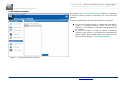
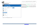
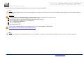
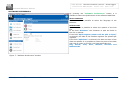
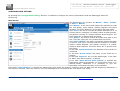
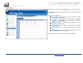
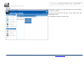
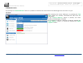
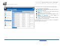
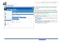
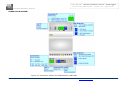
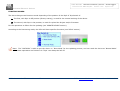
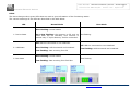
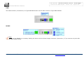
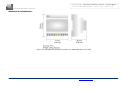
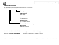
User Manual
Modbus Master/Slave - Datalogger
Document code: MN67324_ENG
Revision 1.002
Page 1 of 27
Industrial Electronic Devices
User Manual
Revision 1.002
English
Modbus Master/Slave - Datalogger
(Order Code: HD67324-B2-U-232-2GB)
(Order Code: HD67324-B2-U-485-2GB)
CAN - Datalogger
(Order Code: HD67324-B2-U-CAN-2GB)
For Website information:
www.adfweb.com?Product=HD67324
For Price information:
www.adfweb.com?Price=HD67324-B2-U-232-2GB
www.adfweb.com?Price=HD67324-B2-U-485-2GB
www.adfweb.com?Price=HD67324-B2-U-CAN-2GB
Benefits and Main Features:
Very easy to use
Low cost
Free updating to lifetime
Power supply of 8…24V AC or 8…35V DC
Isolated RS232/RS485/CAN port
Industrial temperature range:
-20°C / 70°C (-4°F / 158°F)
HD67234-B2-U-xxx-2GB
For other M-Bus products:
See also the following link:
Converter M-Bus to
www.adfweb.com?Product=HD67021
www.adfweb.com?Product=HD67022
www.adfweb.com?Product=HD67030
(RS232)
(RS485)
(Ethernet)
Extender and Repeater, M-Bus
www.adfweb.com?Product=HD67032
Gateway M-Bus / Modbus RTU
www.adfweb.com?Product=HD67029M-232
www.adfweb.com?Product=HD67029M-485
(on RS232)
(on RS485)
Gateway M-Bus / Modbus TCP
www.adfweb.com?Product=HD67044M
Gateway M-Bus / CANopen
www.adfweb.com?Product=HD67051
Gateway M-Bus / PROFIBUS
www.adfweb.com?Product=HD67053M
Do you have an your customer protocol?
See the following link:
www.adfweb.com?Product=HD67003
Do you need to choose a device? do you want help?
Ask it to the following link:
www.adfweb.com?Cmd=helpme
ADFweb.com Srl – IT31010 – Mareno – Treviso
INFO: www.adfweb.com
Phone +39.0438.30.91.31
User Manual
Modbus Master/Slave - Datalogger
Document code: MN67324_ENG
Revision 1.002
Page 2 of 27
Industrial Electronic Devices
INDEX:
UPDATED DOCUMENTATION:
INDEX
UPDATED DOCUMENTATION
REVISION LIST
WARNING
TRADEMARKS
SECURITY ALERT
INTRODUCTION
THE HARDWARE
THE SOFTWARE
CHARACTERISTICS
INSTALLATION
USB DRIVER
USE OF SW67324 DATA LOGGER
NEW CONFIGURAION
LOAD CONFIGURATION
SAVE CONFIGURATION
UPDATE DEVICE
SOFTWARE PREFERENCES
CONFIGURATION SETTING
DOWNLOAD DATA
DATE & TIME SETTINGS
CONNECTION SCHEME
POWER SUPPLY
FUNCTION MODES
LEDS
USB
RS485
MECHANICAL DIMENSIONS
ORDERING INFORMATIONS
ACCESSORIES
DISCLAIMER
OTHER REGULATIONS AND STANDARDS
WARRANTIES AND TECHNICAL SUPPORT
RETURN POLICY
PRODUCTS AND RELATED DOCUMENTS
ADFweb.com Srl – IT31010 – Mareno – Treviso
Page
2
2
2
2
2
3
4
4
4
4
4
4
5
6
7
8
9
11
12
15
17
18
19
20
21
22
22
23
24
25
26
26
27
27
27
Dear customer, we thank you for your attention and we remind you that you
need to check that the following document is:
Updated
Related to the product you own
To obtain the most recently updated document, note the “document code”
that appears at the top right-hand corner of each page of this document.
With this “Document Code” go to web page www.adfweb.com/download/ and
search for the corresponding code on the page. Click on the proper “Document
Code” and download the updates.
To obtain the updated documentation for the product that you own, note the
“Document Code” (Abbreviated written "Doc. Code" on the label on the
product)
and
download
the
updated
from
our
web
site
www.adfweb.com/download/
REVISION LIST:
Revision
1.000
1.001
1.002
1.003
Date
Author
26/08/2011
Fl
28/05/2012
Dp
07/02/2013
Nt
20/05/2013
Fl
Chapter
All
All
All
All
Description
Software changed (v1.000)
Revision
Added new chapters
Add USB driver location
WARNING:
ADFweb.com reserves the right to change information in this manual about
our product without warning.
ADFweb.com is not responsible for any error this manual may contain.
TRADEMARKS:
All trademarks mentioned in this document belong to their respective owners.
INFO: www.adfweb.com
Phone +39.0438.30.91.31
User Manual
Modbus Master/Slave - Datalogger
Document code: MN67324_ENG
Revision 1.002
Page 3 of 27
Industrial Electronic Devices
SECURITY ALERT:
GENERAL INFORMATION
To ensure safe operation, the device must be operated according to the instructions in the manual. When using the device are required for
each individual application, legal and safety regulation. The same applies also when using accessories.
INTENDED USE
Machines and systems must be designed so the faulty conditions do not lead to a dangerous situation for the operator (i.e. independent limit
switches, mechanical interlocks, etc.).
QUALIFIED PERSONNEL
The device can be used only by qualified personnel, strictly in accordance with the specifications.
Qualified personnel are persons who are familiar with the installation, assembly, commissioning and operation of this equipment and who
have appropriate qualifications for their job.
RESIDUAL RISKS
The device is state of the art and is safe. The instrument can represent a potential hazard if they are inappropriately installed and operated
by personnel untrained. These instructions refer to residual risks with the following symbol:
This symbol indicates that non-observance of the safety instructions is danger for people to serious injury or death and / or the
possibility of damage.
CE CONFORMITY
The declaration is made by us. You can send an email to [email protected] or give us a call if you need it.
ADFweb.com Srl – IT31010 – Mareno – Treviso
INFO: www.adfweb.com
Phone +39.0438.30.91.31
User Manual
Modbus Master/Slave - Datalogger
Document code: MN67324_ENG
Revision 1.002
Page 4 of 27
Industrial Electronic Devices
INTRODUCTION:
The Datalogger is a powerful, flexible and economic instrument that can be used with systems based on Modbus 232, Modbus 485 or CAN.
The instrument is composed of the following: module hardware with a RS232 or RS485 or CAN, USB interface that connects to a personal
computer and a free software for MS Windows.
THE HARDWARE:
The
The
The
The
The
model of “Datalogger B2-U-xxx-2GB” can be used with the SW67324 using the USB to connect to the PC.
B2 value indicate the kind of box and the dimension of the device: B2.
U value indicates the communication port for the software connection and re-programming of the board: U for USB.
xxx value shows the port to which the device is connected: 485 for RS485, 232 for RS232.
2GB value shows the dimension of the memory of the unit: 2Gb.
THE SOFTWARE:
To obtain the software please go to http://www.adfweb.com/home/download/download.asp (This manual is referenced to the last version of
the software present on our web site). The software works with MSWindows (MS 2000, XP).
CHARACTERISTICS:
This product has the following characteristics:
Electrical isolation for bus ( RS232, RS485 or CAN) connection;
Mountable on Rail DIN;
Power Supply 8…24V AC or 8…35V DC;
Temperature range -20°C to 70°C.
INSTALLATION:
Extract the file downloaded from our web site and follow the procedure to install the software.
USB DRIVER:
The driver for the USB port can be found in the installation folder of SW67324, under the folder “Extras”. Usually the path is the following:
C:\<Program Files>\ADFweb\Datalogger_SW67324\Extras
ADFweb.com Srl – IT31010 – Mareno – Treviso
INFO: www.adfweb.com
Phone +39.0438.30.91.31
User Manual
Modbus Master/Slave - Datalogger
Document code: MN67324_ENG
Revision 1.002
Page 5 of 27
Industrial Electronic Devices
USE OF SW67324 DATALOGGER:
Figure 1: Main window for SW67324
ADFweb.com Srl – IT31010 – Mareno – Treviso
INFO: www.adfweb.com
Phone +39.0438.30.91.31
User Manual
Modbus Master/Slave - Datalogger
Document code: MN67324_ENG
Revision 1.002
Page 6 of 27
Industrial Electronic Devices
NEW CONFIGURATION:
By pressing the “New Configuration” button it is possible
to create a new project assigning the name in the field near
the button “OK” that is used for create it.
Figure 2: “New Configuration” window
ADFweb.com Srl – IT31010 – Mareno – Treviso
INFO: www.adfweb.com
Phone +39.0438.30.91.31
User Manual
Modbus Master/Slave - Datalogger
Document code: MN67324_ENG
Revision 1.002
Page 7 of 27
Industrial Electronic Devices
LOAD CONFIGURATION:
By pressing the “Load Configuration” button it is possible
to load an existing project by selecting one of the list that
appears.
A device configuration can also be imported or exported:
To clone the configurations of a DataLogger RS485 in
order to configure another device in the same
manner, it is necessary to maintain the folder and all
its contents;
To clone a project in order to obtain a different
version of the project, it is sufficient to duplicate the
project folder with another name and open the new
folder with the button “Load Configuration”.
Figure 3: “Load Configuration” window
ADFweb.com Srl – IT31010 – Mareno – Treviso
INFO: www.adfweb.com
Phone +39.0438.30.91.31
User Manual
Modbus Master/Slave - Datalogger
Document code: MN67324_ENG
Revision 1.002
Page 8 of 27
Industrial Electronic Devices
SAVE CONFIGURATION:
By pressing the “Save Configuration” button it is possible
to save the project.
There are two possibilities: or save the current configuration,
by pressing the button “Save”; or save with a new name by
pressing the button ”Save As...” and writing the name in the
field above the button.
Figure 4: “Save Configuration” window
ADFweb.com Srl – IT31010 – Mareno – Treviso
INFO: www.adfweb.com
Phone +39.0438.30.91.31
User Manual
Modbus Master/Slave - Datalogger
Document code: MN67324_ENG
Revision 1.002
Page 9 of 27
Industrial Electronic Devices
UPDATE DEVICE:
By pressing the “Update Device” button it is possible to
load the created Configuration into the device; and also the
Firmware, if is necessary.
For doing this follow these instructions:
Connect the USB cable from the PC to the device;
Select the COM port;
Select which operations you want to do. You can
select only “Write Firmware”, only “Write
Configuration” or both of them;
Press the “Update Device” button to start the
upload.
When all operations are “OK” the Configuration/Firmware on
the device is correctly updated.
For the updating, the device must be on Boot Mode. This
modality is self-managed by the SW67324. So when you
press the “Update Device” button the device is automatically
put on Boot Mode and when it have complete the operations
is put on Normal Mode.
Figure 5: “Update Device” window
However if the device doesn’t go to Boot Mode automatically
it is necessary to act on the ‘Dip-Switch A’ (see ‘FUNCTION
MODES’ section for found the correct Dip) and it is necessary
to follow these instructions:
Put the device at Boot Mode by Dip1 of ‘Dip-Switch A’;
Turn On the device;
Check the LEDs. LED1 and LED3 must blink quickly;
Connect the USB cable from the PC to the device;
Select the COM port;
Select which operations you want to do. You can select only “Write Firmware”, only “Write Configuration” or both of them;
Press the “Update Device” button to start the upload;
When all operations are “OK” put the device at Normal Mode by Dip2 of ‘Dip-Switch A’.
ADFweb.com Srl – IT31010 – Mareno – Treviso
INFO: www.adfweb.com
Phone +39.0438.30.91.31
User Manual
Modbus Master/Slave - Datalogger
Document code: MN67324_ENG
Revision 1.002
Page 10 of 27
Industrial Electronic Devices
At this point the Configuration/Firmware on the device is correctly updated.
Note:
When you install a new version of the software it is better if the first time you do the update of the Firmware in the HD67324-B2-Uxxx-2GB device.
Warning:
If the update isn’t completedwith success, before require assistance try these points:
Check if the serial COM port selected is the correct one;
Check if the Cable is connected between the PC and the device;
Try to repeat the operations for the updating;
Try to use another USB port;
Try to restart the PC;
Try with another PC.
In the case of HD67324-B2-U-xxx-2GB you have to use the software “SW67324”:
www.adfweb.com/download/filefold/SW67324.zip.
Note:
For the updating of Firmware/Project it isn’t necessary to use the external Power Supply, the one given by USB is sufficient.
ADFweb.com Srl – IT31010 – Mareno – Treviso
INFO: www.adfweb.com
Phone +39.0438.30.91.31
User Manual
Modbus Master/Slave - Datalogger
Document code: MN67324_ENG
Revision 1.002
Page 11 of 27
Industrial Electronic Devices
SOFTWARE PREFERENCES:
By pressing the “Software Preferences” button it is
possible to select the preferences of the software SW67324.
SELECT LANGUAGE
In this section is possible to select the language of the
software.
CSV OPTIONS
In this section is possible to select the options of the CSV
file.
In the field “Delimiter” the character to split the fields in
CSV file is defined.
If the field “Split Register (Status will be split in byte)”
is checked, the data of the modbus registers are splitted per
registers.
If the field “Split Date” is checked, the date and time of the
data are splitted. It is possible to select the parts of the date
and time to insert in CSV file, the fields selectable are:
Day, Month, Year, Hour, Minutes, Seconds and
Milliseconds.
Figure 7: “Software Preferences” window
ADFweb.com Srl – IT31010 – Mareno – Treviso
INFO: www.adfweb.com
Phone +39.0438.30.91.31
User Manual
Modbus Master/Slave - Datalogger
Document code: MN67324_ENG
Revision 1.002
Page 12 of 27
Industrial Electronic Devices
CONFIGURATION SETTING:
By pressing the “Configuration Setting” button it is possible to configure the various informations that the DataLogger wants for
functioning.
MAIN OPTION
The DataLogger can function as ‘Master’, ‘Slave’, ‘Sniffer’
or ‘Slave + Sniffer’.
Like “Master” is the device that makes the requests for read
the Coil Status, Input Status, Holding Register and Input
Register. The Field “Slave ID” isn’t present with this mode.
Like “Slave” the device records all frames addressed to it. It
answer with an exception if a master makes a Read Request,
and answer correctly if a master makes a Write Request. The
Field “Slave ID” is present with this mode.
Like “Sniffer” the device records all frames that pass in the
line. The Field “Slave ID” isn’t present with this mode.
Like “Slave+Sniffer” the device records all frames that pass
in the line. And more, it answer with an exception if a master
makes a Read Request, and answer correctly if a master
makes a Write Request. The Field “Slave ID” is present with
this mode.
In the field “Serial Baudrate” the Baudrate of the serial line
is defined.
In the field “Serial Parity” the parity of the serial line is
defined.
In the field “Slave ID” the id of the DataLogger, in the case
of ‘Slave’ and ‘Slave+Sniffer’, is defined.
If the field “Start Record when Reboot” is checked the
DataLogger starts automatically to record data (when is in
Normal Mode). Otherwise it is necessary to give the
Start/Stop commands manually, by the software.
If the field “Cyclic Memory” is checked the DataLogger when finish the memory restart to save the data from the beginning. Otherwise, if
the field isn’t checked, when the memory is full the messages aren’t stored and the Led1 blinks very slowly.
ADFweb.com Srl – IT31010 – Mareno – Treviso
INFO: www.adfweb.com
Phone +39.0438.30.91.31
User Manual
Modbus Master/Slave - Datalogger
Document code: MN67324_ENG
Revision 1.002
Page 13 of 27
Industrial Electronic Devices
POLLS TABLE
This section is used only if the Datalogger is set like ‘Master’.
In the table the various requests that the DataLogger sends
are defined.
The fields to compile are:
“ID Device”: is the ID of the slave device to which
the request will be made;
“Function”: is the type of request used. It is possible
to define 1: Coil Status, 2: Input Status, 3: Holding
Register, 4: Input Register;
“Address Reg.”: is the starting address of the
registers to be required;
“N° Points”: is the number of consecutive registers
to be required;
“Poll Time [ms]”: is the time between to polls of the
row;
“Description”: in this field it is possible to insert a
short description of the request.
It is possible to define up to 1024 different requests.
ADFweb.com Srl – IT31010 – Mareno – Treviso
INFO: www.adfweb.com
Phone +39.0438.30.91.31
User Manual
Modbus Master/Slave - Datalogger
Document code: MN67324_ENG
Revision 1.002
Page 14 of 27
Industrial Electronic Devices
IDS LIST
This section is used only if the Datalogger is set like ‘Sniffer’
or “Slave + Sniffer”.
In the left list there are the IDs of the slaves that the
DataLogger sniffs.
It is possible to define up to 247 IDs.
ADFweb.com Srl – IT31010 – Mareno – Treviso
INFO: www.adfweb.com
Phone +39.0438.30.91.31
User Manual
Modbus Master/Slave - Datalogger
Document code: MN67324_ENG
Revision 1.002
Page 15 of 27
Industrial Electronic Devices
DOWNLOAD DATA:
By pressing the “Download Data” button it is possible to download the stored data of the DataLogger and see them in a grid.
GET DATA
After selecting the correct COM port, by pressing the “Get
Data” button the software downloads the data from the
DataLogger.
If the “Cancel Memory” button is pressed, the entire
memory of DataLogger is cleared.
It is possible to stop the capturing of data by pressing the
“Stop Capture” button, or resume by pressing the “Start
Capture” button.
ADFweb.com Srl – IT31010 – Mareno – Treviso
INFO: www.adfweb.com
Phone +39.0438.30.91.31
User Manual
Modbus Master/Slave - Datalogger
Document code: MN67324_ENG
Revision 1.002
Page 16 of 27
Industrial Electronic Devices
GRID
In this section there is the grid with the downloaded data.
The grid is composed of the follows:
“Date Time”: is the date and time when the reply to
the request is arrived;
“Slave ID”: is the ID of the slave device that has
replied;
“Data Type”: is the type of reply;
“Address Register”: is the starting address of the
reply;
“Number of Registers”: is the number of
consecutive registers of the reply;
“Data”: in this column there are the data, the value
is expressed in decimal format.
By pressing the “Save in CSV file” button it is possible to
export the data into a CSV file.
ADFweb.com Srl – IT31010 – Mareno – Treviso
INFO: www.adfweb.com
Phone +39.0438.30.91.31
User Manual
Modbus Master/Slave - Datalogger
Document code: MN67324_ENG
Revision 1.002
Page 17 of 27
Industrial Electronic Devices
DATE & TIME SETTING:
By pressing the “Date & Time Setting” button it is possible
to update/read the DataLogger data/time and having other
informations.
After selecting the correct COM port where the Datalogger is
connected to the PC, by pressing the “Set Custom Date &
Time” it is possible to set the data/time that is written in the
fields upper; by pressing the “Set PC Date & Time” button
the data setted are the ones of the PC.
By pressing the “Read Status Device” are read some
information about the DataLogger:
“Data Time”: is the current data and time of the
DataLogger;
“Firmware Version”: is the firmware version of the
DataLogger;
“Saved Event”: are the numbers of Modbus events
and some other commands saved;
“Used Memory”: is the number of bytes used by the
datalogger for storing data.
ADFweb.com Srl – IT31010 – Mareno – Treviso
INFO: www.adfweb.com
Phone +39.0438.30.91.31
User Manual
Modbus Master/Slave - Datalogger
Document code: MN67324_ENG
Revision 1.002
Page 18 of 27
Industrial Electronic Devices
CONNECTION SCHEME:
Figure 32: Connection scheme for HD67324-B2-U-485-2GB
ADFweb.com Srl – IT31010 – Mareno – Treviso
INFO: www.adfweb.com
Phone +39.0438.30.91.31
User Manual
Modbus Master/Slave - Datalogger
Document code: MN67324_ENG
Revision 1.002
Page 19 of 27
Industrial Electronic Devices
POWER SUPPLY:
The devices can be powered at 8…24V AC and 8…35V DC. The consumption depends to the code of the device.
Consumption at 24V DC:
Device
No Load [W/VA]
HD67324-B2-U-485-2GB
HD67324-B2-U-232-2GB
1,5 max
Caution: Not reverse the polarity power
HD67234-B2-U-xxx-2GB
ADFweb.com Srl – IT31010 – Mareno – Treviso
INFO: www.adfweb.com
Phone +39.0438.30.91.31
User Manual
Modbus Master/Slave - Datalogger
Document code: MN67324_ENG
Revision 1.002
Page 20 of 27
Industrial Electronic Devices
FUNCTION MODES:
The device has got two functions mode depending of the position of the Dip2 of ‘Dip-Switch A’:
The first, with Dip1 in Off position (factory setting), is used for the normal working of the device.
The second, with Dip1 in On position, is used for upload the Project and/or Firmware.
For the operations to follow for the updating (see ‘UPDATE DEVICE’ section).
According to the functioning mode, the LEDs will have specifics functions (see ‘LEDS’ section).
Note: The “SW76324” is able to put the device in ‘Boot Mode’ for the updating process, and can send the device at ‘Normal Mode’
when these operations are finished. So ‘‘Dip1’ can always be left off.
ADFweb.com Srl – IT31010 – Mareno – Treviso
INFO: www.adfweb.com
Phone +39.0438.30.91.31
User Manual
Modbus Master/Slave - Datalogger
Document code: MN67324_ENG
Revision 1.002
Page 21 of 27
Industrial Electronic Devices
LEDS:
The device has got three green LEDs that are used to give information of the functioning status.
The various meanings of the LEDs are described in the table below.
LED
Normal Mode
Boot Mode
Slow flashing: normal status
1: Device State
Very slow flashing: the memory is full, and no
other data will be recorded. This function is
present only if “Cyclic Memory” field is unchecked.
Fast flashing
Off: USB not connected or not initialized.
Off: USB not connected or not initialized.
2: USB State
Slow flashing: USB Connected and initialized
Fast flashing: USB Connected and initialized
Fast flashing: data receiving from PC
Slow flashing: normal status
3: Bus State
Slow flashing
Fast flashing: data receiving from field bus
ADFweb.com Srl – IT31010 – Mareno – Treviso
INFO: www.adfweb.com
Phone +39.0438.30.91.31
User Manual
Modbus Master/Slave - Datalogger
Document code: MN67324_ENG
Revision 1.002
Page 22 of 27
Industrial Electronic Devices
USB:
The USB connector (Connector2) is a Type-MINI AB Female. So the cable must be a Type-MINI AB Male.
RS485:
Note:
For use the RS485 it is necessary feeding the device with the Power Supply connector (Connector1). If you connect only the USB
cable the port doesn’t works.
ADFweb.com Srl – IT31010 – Mareno – Treviso
INFO: www.adfweb.com
Phone +39.0438.30.91.31
User Manual
Modbus Master/Slave - Datalogger
Document code: MN67324_ENG
Revision 1.002
Page 23 of 27
Industrial Electronic Devices
MECHANICAL DIMENSIONS:
Figure 33: Mechanical dimensions scheme for HD67234-B2-U-xxx-2GB
ADFweb.com Srl – IT31010 – Mareno – Treviso
INFO: www.adfweb.com
Phone +39.0438.30.91.31
User Manual
Modbus Master/Slave - Datalogger
Document code: MN67324_ENG
Revision 1.002
Page 24 of 27
Industrial Electronic Devices
ORDERING INFORMATIONS:
The ordering part number is formed by a valid combination of the following:
HD67324 – B 2 – U - xxx – 2GB
Memory
2 Gb = 2 GigaBytes
BUS connection
485 = RS485
232 = RS232
CAN = CAN bus
PC software connection
U=USB Connection
Connectors Type
2 = Fixed Screw Terminal
Enclosure Type
B = Modulbox 4M DIN Rail mounting
Device Family
HD67324 = Datalogger
Order Code: HD67324-B2-U-485-2GB
Data Logger for Modbus on RS485 with 2 Gigabytes of memory
Order Code: HD67324-B2-U-232-2GB
Data Logger for Modbus on RS232 with 2 Gigabytes of memory
Order Code: HD67324-B2-U-CAN-2GB
Data Logger for CAN bus with 2 Gigabytes of memory
ADFweb.com Srl – IT31010 – Mareno – Treviso
INFO: www.adfweb.com
Phone +39.0438.30.91.31
User Manual
Modbus Master/Slave - Datalogger
Document code: MN67324_ENG
Revision 1.002
Page 25 of 27
Industrial Electronic Devices
ACCESSORIES:
AC34107
-
Null Modem Cable Fem/Fem DSub 9 Pin 1,5 m
AC34114
-
Null Modem Cable Fem/Fem DSub 9 Pin 5 m
AC34001
-
Rail DIN Power Supply 220/240V AC 50/60Hz – 12 VAC
AC34002
-
Rail DIN Power Supply 110V AC 50/60Hz – 12 VAC
ADFweb.com Srl – IT31010 – Mareno – Treviso
INFO: www.adfweb.com
Phone +39.0438.30.91.31
User Manual
Modbus Master/Slave - Datalogger
Document code: MN67324_ENG
Revision 1.002
Page 26 of 27
Industrial Electronic Devices
DISCLAIMER
All technical content within this document can be modified without notice. The content of the document content is a recurring audit.
For losses due to fire, earthquake, third party access or other accidents, or intentional or accidental abuse, misuse, or use under abnormal
conditions repairs are charged to the user. ADFweb.com S.r.l. will not be liable for accidental loss of use or inability to use this product, such
as loss of business income. ADFweb.com S.r.l. shall not be liable for consequences of improper use.
OTHER REGULATIONS AND STANDARDS
WEEE INFORMATION
Disposal of old electrical and electronic equipment (as in the European Union and other European countries with separate
collection systems).
This symbol on the product or on its packaging indicates that this product may not be treated as household rubbish. Instead, it
should be taken to an applicable collection point for the recycling of electrical and electronic equipment. If the product is disposed
correctly, you will help prevent potential negative environmental factors and human health, which could otherwise be caused by
inappropriate disposal. The recycling of materials will help to conserve natural resources. For more information about recycling this
product, please contact your local city office, your household waste disposal service or the shop where you purchased the product.
RESTRICTION OF HAZARDOUS SUBSTANCES DIRECTIVE
The device respects the 2002/95/EC Directive on the restriction of the use of certain hazardous substances in electrical
and electronic equipment (commonly referred to as Restriction of Hazardous Substances Directive or RoHS).
CE MARKING
The product conforms with the essential requirements of the applicable EC directives.
ADFweb.com Srl – IT31010 – Mareno – Treviso
INFO: www.adfweb.com
Phone +39.0438.30.91.31
User Manual
Modbus Master/Slave - Datalogger
Document code: MN67324_ENG
Revision 1.002
Page 27 of 27
Industrial Electronic Devices
WARRANTIES AND TECHNICAL SUPPORT:
For fast and easy technical support for your ADFweb.com SRL products, consult our internet support at www.adfweb.com.
Otherwise contact us at the address [email protected].
RETURN POLICY:
If while using your product you have any problem and you wish to exchange or repair it, please do the following:
1) Obtain a Product Return Number (PRN) from our internet support at www.adfweb.com. Together with the request, you need to provide detailed information
about the problem.
2) Send the product to the address provided with the PRN, having prepaid the shipping costs (shipment costs billed to us will not be accepted).
If the product is within the warranty of twelve months, it will be repaired or exchanged and returned within three weeks. If the product is no longer under warranty,
you will receive a repair estimate.
PRODUCTS AND RELATED DOCUMENTS:
Part
Description
URL
HD67031
Analyzer / Scanner / Sniffer M-Bus
www.adfweb.com?product=HD67031
HD67119
Converter USB 2.0 to RS485 Isolated
www.adfweb.com?product=HD67119
HD67316
CAN, CANopen, J1939, DeviceNet, NMEA2000 Analyzer
www.adfweb.com?Product=HD67316
HD67507
Gateway Modbus TCP Server to RTU Master
www.adfweb.com?product=HD67507
HD67510
Gateway Modbus TCP Client to RTU Slave
www.adfweb.com?product=HD67510
ADFweb.com Srl – IT31010 – Mareno – Treviso
INFO: www.adfweb.com
Phone +39.0438.30.91.31