1
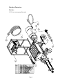
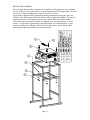
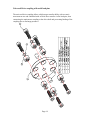
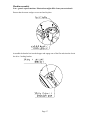
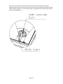
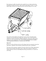
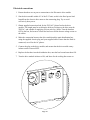
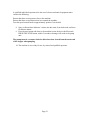
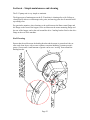
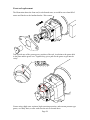
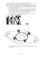
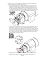
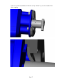
Ease the pump assembly into position, then assemble the two wedges into the slots.
Manipulate the pump unit and the wedges until the pump flange is within 1/8” of the
hopper flange, then drive the wedges into position until both flange faces are flush.
Note: the drive shaft might become tight between the two drive slots during static
assembly. Once the unit has been running the compressive force will be reduced or
eliminated to within working limits. During pumping the compression will be present,
during reverse the compression will be relieved. Do not operate in reverse unless
removing pressure in the hoses or excessive wear will result
Important
Replace the safety grid back onto the top of the hopper and secure using the 4 clips, bolts
and washers. Operation of this machinery without the grid in place is prohibited.
The output of the pump unit is supplied with a male cam-lock style fitting which threads
directly onto the output of the pump, giving a 50mm male connection, suitable for a
50mm female hose cam-lock, and subsequent discharge from the hose via a male camlock fitting.
Page 19