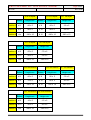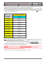
1
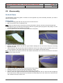
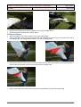
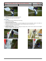
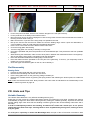
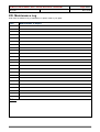
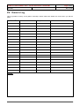
Icaro LAMINAR - Instructions Manual 04.04.06 Page 1/ 27 Rev. 02.06 User’s Manual Rev.02.06 Icaro LAMINAR - Instructions Manual 04.04.06 Page 2/ 27 Rev. 02.06 Congratulations on buying an Icaro 2000 hang glider! We’re certain that you’ve made the right choice! The new Laminar represents the greatest technological improvement in the last years; hang gliding will not be like it used to be. Icaro 2000 srl is among the world's leading hang glider manufacturers, building more than 8,000 hang gliders in the last twenty-two years. Icaro 2000’s competition and sales record are the envy of other manufacturers… Icaro 2000 gliders are fully designed and manufactured in our factory at Sangiano –Northern Italy, using only first quality materials. The development of our wings is the result of, the four-times World Champion Manfred Ruhmer (two Cross Country titles, 1 Speed Gliding and one Class V title), and our twenty-year experience in hang gliders manufacture. All our hang gliders have German certification (DHV). With our extensive worldwide distributor’s network, you can rest assured that spare parts and service will always be available to you, no matter where you fly. This includes spares for all current and dated models. Thank you for choosing our hang gliders and we wish you great flights! Icaro 2000 srl via Verdi, 19 I-21038-Sangiano ITALY Phone:+39 (0332) 648335 Fax: +39 (0332) 648079 E-mail: [email protected] WEB: www.icaro2000.com Icaro LAMINAR Z8- Instructions Manual 04.04.06 Page 3/27 Rev. 02.06 Table of Contents PREFACE 4 I. INTRODUCTION Keep risks to a minimum Preliminaries Assembly check and first flight High flights 9 9 9 9 9 II. FUNDAMENTAL RULES 10 III. CERTIFICATION AND GENERAL RESTRICTIONS Certification Wind speed Turbulence Aerobatic Flying 11 11 11 11 11 IV. TRANSPORT By car By Gondola or Cable car In Plane Short packing the hang glider 12 12 12 12 12 V. ASSEMBLY Assembly on the A-Frame Start point Mounting the fiberglas tips Positioning the aluminium tip Fixing the Crossbar Inserting the battens Final operations 13 13 13 14 14 15 15 15 Flat assembly Start point Final checking 15 15 16 VI. CHECK LIST Assembly check Symmetry Equipment check Pre-flight check 17 17 18 18 18 VII. DISASSEMBLY ON A-FRAME Start point Folding the sail wingtips Final operations 19 19 20 21 Flat disassembly Start point 21 22 Icaro LAMINAR Z8- Instructions Manual 04.04.06 Page 4/27 Rev. 02.06 VIII. HINTS AND TIPS Variable Geometry Take off Flight Landing 23 23 23 23 24 IX. TRIM Speed Turns Winch and UL-Towing 25 25 25 25 X. ADJUSTMENT VALUES Swivel tip height 26 26 XI. RECOMMENDATIONS Motorization 27 27 XII. REPAIR AND PERIODIC INSPECTION 28 XIII. TECHNICAL DATA 29 XIV. MAINTENANCE LOG 30 XV. OWNER’S LOG 31 Icaro LAMINAR Z8- Instructions Manual 04.04.06 I. Page 5/27 Rev. 02.06 Introduction Over the last decade hang gliding has become much safer. Accidents have diminished, due to flight-schools becoming more professional, and certification procedures becoming more demanding. In Switzerland, for example, the insurance risk for hang gliding is the same as for winter sports. However, hang gliding is an active sport with certain associated risks. Your safety can be greatly enhanced by following a few simple rules: Keep Risks to a Minimum Attend a professional school. Fly a glider suited to your skills. In order to fly the new Z8 you should be an advanced pilot with at least 100 hours on another hang glider. Fly only when the weather conditions are appropriate. Be aware of adverse weather conditions; caution is a mark of intelligence not of cowardice. Remain current. Try to avoid long intervals between one flight and the next so your flying ability will gradually increase. A new risk may arise when you fly a new type of glider for the first time. The reactions of your new glider may well differ from those of the glider you were used to. In order to keep this risk low, we recommend that you gradually become familiar with your new glider and make your first flight in calm conditions. Preliminaries Study your manual before your first flight. Practice assembly and disassembly as explained in the manual. Always follow the same assembly and pre-flight check routine; do not distract yourself during these procedures! Assembly Check and First Flight Every authorized ICARO 2000 dealer can test fly your glider or –if requested– before delivery; consider asking for it, you'll get your money's worth. Your dealer should also help you set up your glider for the first time and see you off on your first flight. We strongly recommend speedbar wheels, especially for your first flights. High Flights Always wait for ideal weather conditions for your first high flight. Experiment with different VG settings: roll reversals, slow flight, high speed flight and stalls at an altitude of at least 350m (±1000 feet). Fly your personal polar with your own instruments. II. Fundamental Rules After major repairs, after replacing the sail or after a long period of not flying, always choose a site to fly from that you are familiar with; and where it is possible to land immediately after take-off. Your glider is delivered to you ready to fly. DO NOT make any adjustments that are not described in this manual. Periodically check the trimming values shown in the tables (Chapter IX). Fly only after having attended a good school, recognized by your hang gliding federation. This Owner's Manual does not replace the check done by an authorized dealer. This counts also for expert pilots. Any pilot who is in doubt about any aspect of their glider should consult their dealer, or ICARO 2000, for advice. Never fly alone. Before every take-off always do both an assembly check and a pre-flight check. Don’t push your luck! Fly only in places suited for hang gliding. It's your responsability to know the limits of your glider, and the limits of your own experience. Don’t attempt towing of any kind, unless you have attended a recognized towing school. Always use wheels on your speedbar when towing. Icaro LAMINAR Z8- Instructions Manual 04.04.06 III. Page 6/27 Rev. 02.06 Certification and General Restrictions Certification All ICARO 2000 hang gliders have German certification (DHV). Icaro gliders are rated according to the German DHV in the following manner: Class 1 (beginner pilots) – RELAX and Mars Class 2 (intermediate pilots) – Easy, Orbiter Class 2-3 (advanced pilots) – MasteR Class 3 (advanced pilots) – Laminar Z8 Wind Speed When the wind speed is stronger than 30 km/h (~15 mph) take off becomes risky. In these conditions, consult with more experienced pilots before launching. If in doubt, do not fly. Turbulence In turbulent conditions, gusts of descending air can suddenly exert strong negative loads on the glider; such negative loads must be avoided. Do not fly in turbulent conditions or on the lee side of a mountain; this is extremely risky in strong winds. Aerobatic Flying AEROBATIC FLIGHT CAN BE FATAL AND IS , THEREFORE , PROHIBITED BY ICARO 2000 AND BY THE GERMAN FEDERATION (DHV). Aerobatic flight includes flying with bank angles greater than 60 , pitch angles greater than 30 , whip-stalls, wingovers, loops and spins. Icaro LAMINAR Z8- Instructions Manual 04.04.06 IV. Page 7/27 Rev. 02.06 Transport By Car Serious damage can be caused to the glider during car transportation; a well-padded roof rack is necessary to avoid damage. For additional safety and support, we strongly suggest you to install a front rack on your vehicle. There are good racks on the market, especially designed for glider transport; these can be easily set up on normal roof racks. Ask your dealer for details. By Gondola or Cable car To avoid any damage when transporting your glider on the cable car it is advisable to be present to supervise the loading and unloading of the glider. By Plane Your glider needs to be thoroughly protected if it is to be transported by plane. Use a wooden crate, or a stiff cardboard tube. Your dealer or ICARO 2000 can provide these. Always let the airline know the dimensions and weight of your glider, well in advance. Short Packing Avoid short packing your glider; this may result in a crease on the leading edge’s Mylar on both wings. To short pack your glider it is important to follow these instructions: 1. Make sure you write down how to re-assemble every part afterwards. 2. Undo the sail fastening on the end of the leading edge tube. 3. Remove the pin holding the compensator cable attached to the swivel tip lever. 4. Replace the pin in order not to lose it. 5. Press the spring button on the rear leading edge and remove it. 6. Be careful not to wrinkle the Mylar leading edge insert too much when you fold the sail; it is also possible to take it out. 7. Cover the outer leading edge tubes with a soft material. 8. Fold the wingtips as you normally do. Make sure you protect the end of the leading edge tube and if possible use a carton roll to fold the sail around it in order to diminish the sail and Mylar damages. Repeat steps 2-8 on the other wing. To re-assemble your wing follow the instructions in the inverse order. The length of the wing will be as reported below: Laminar cm / ft Z8 12.9 Z8 13.2 Z8 13.7 Z8 14.1 Z8 14.8 140 / ~4 7 108 / ~3 7 108.0/ ~3 7 110.0/ ~3 6 110.0/ ~3 6 Make sure the spring buttons pops up when re-assembling the leading edge tube. Remember to hook the compensator cable in and make sure it is not tangled around the tube. Icaro LAMINAR Z8- Instructions Manual 04.04.06 V. Page 8/27 Rev. 02.06 Assembly There are two possibilities to assemble your LAMINAR Z8 properly: On the A-frame: This method helps you protect your glider in an excellent manner because the sail practically never touches the ground; this avoids scratches and dirt on your sail. Flat assembly: This method is only recommended when setting up in strong wind conditions. Left and right in this section must be understood as in flight position. Assembly on the A-frame Place the glider on the ground With light breeze: nose into the wind With moderate breeze: the keel must be perpendicular to the wind If the ground where you are assembling the glider is not flat, point the nose of the glider towards the top of the slope. Starting Point Open the glider bag, remove the Velcro, pull the uprights out and fix the speedbar with the pushpins and safety rings. Do not forget the safety rings! (The competition A-Frame does not have these rings). Make sure that the camber of the speedbar faces the nose of the glider. When you turn the glider over, the center of the speedbar touches the ground first (carbon speedbars can only be assembled the right way). Turn the glider over and lean it on the A-frame so it stands stable. Remove the glider bag and any remaining ties. Partially open the wings keeping the end of the wings very close to the ground and the tip covers on. Position the carbon SPU (it is a substantially large carbon tube braced by a steel wire placed on the crossbar/half-wing junction, which supports battens nr. 6, 7 and 8 on the Z8 12.9; and battens nr. 7, 8 and 9 on all remaining sizes). In order to position the SPU, you need to take the final part of it, the part that is flat and covered, and raise it until it is possible to insert the front part in the adapter. Make sure that the SPU wire is free and runs parallel to the SPU: it must not be twisted around the tube! In order to complete the positioning of the SPU, you need to close the zipper beneath it; this needs to be done after having inserted all the battens. Repeat the same procedure on the other wing. Open the wings completely Make sure that the VG is totally loose and that the wings are completely open. Pull the bungee on the rear part of the keel until you can grasp the handle. Pull it until you reach the small screw on the keel and hook the plate in by pushing the two spring buttons (on the Z8, with loose VG, the sail has less tension than on the other models; therefore it is possible to hook the cross bar in before inserting the battens. This sequence needs to be followed in order to avoid the compensator tip wires from giving you problems while assembling the hang glider). Detach the nose cone Velcro. Take the shackle that is attached to the front wires and secure it on the nose hook. In order to do this, you need to slightly force the nose downwards using the special handle. On the Z8 there is a small safety cord attached to the front wires’ shackle. On the one hand, if the crossbar is not completely opened, it will not be possible for you to hook the front wires in. On the other hand, once the front wires are secured, it will be impossible to close the glider even if the crossbar is not hooked in. Icaro LAMINAR Z8- Instructions Manual 04.04.06 Page 9/27 Rev. 02.06 Bear in mind that the fact of having the front wires secured in place doesn’t necessarily mean that the crossbar is also hooked in. This safety cord will avoid, in this case, that the wing closes after take off; but it will be crucial to go straight for landing without making any strong maneuvers. Do not, therefore, omit this point from your pre-flight checklist. Replace the nose cone. You will only need to secure the lower Velcroes because on the upper part there is a bungee that guides the nose cone into place. Do not lift the glider from the keel if the glider is not properly tensioned, this may damage the nose plates and screws. If the wind is not too strong, you can take out the end of the keel by means of the spring button and lean the hang glider on the keel end (see picture on pg 18). This makes the assembly more comfortable. Mounting the Fiberglas Tips Remove the wingtip cover and open the zipper on the end of the sail. Insert the shortest straight batten (it is made of carbon on all our hang glider models) in the pocket located inside the sail, parallel to the trailing edge and secure it with the Velcro. Insert the thick end of the fibreglass tip in the aluminium hole at the end of the leading edge tube. Push firmly until you hear the tip hitting against the stopper (clack!). Standing in front of the glider, hold the leading edge on one hand and the wingtip on the other hand. Bend (not pull) the thin end of the tip towards the trailing edge and, at the same time, position the tip-lever cap over it. Using the attached cord, push the tip-lever into the sail until it “clicks” against the Fiberglas tip. Now the sail is tensioned. Warning: Pay attention to your fingers while closing the lever! Close the wingtip zipper. At this stage, the sail may not be flat but slightly twisted. If so, twist the end of the sail slightly to make it flat; failing to do this could create a subtle turn when flying. Positioning the Aluminum tip Note: In the pictures here below you will see the battens already inserted in the sail. Keep in mind that it is necessary and appropriate to position the tip before inserting the battens Hold the rear part of the tip (not attached to the leading edge tube), located in the final part of the wing, and rotate it clockwise (towards the trailing edge) until you can place it inside the sail. Icaro LAMINAR Z8- Instructions Manual 04.04.06 Page 10/27 Rev. 02.06 Make sure that the tip wire is free and running parallel to the tip; it must not be twisted upon itself! In order to complete the positioning of the tip, you need to close the zipper on the sail; this needs to be done after having inserted the battens. Repeat the same procedure on the other wing. Inserting the Battens The red battens go on the left wing and the green ones on the right wing. Take them out of the bag and lay them down on the ground on the correct side. Start from the center of the hang glider, begin with the longest one and continue outwards until you insert the smallest batten. Place them in their batten pocket and secure them on the trailing edge. Then insert the straight battens in their pockets on the double surface. Note: The number of battens may vary according to the hang glider model. The nose battens may remain in the glider at all times. Final Steps It is now possible to close the Aluminum tips and the SPU’s zippers. Simply closing the zippers will automatically secure the position of the tips and the SPU’s, thanks to a special ribbon. Open the central zipper, which is under the keel and check that, the T-junction the hang strap is attached to, is perpendicular to the keel. Close the zipper making sure that both sliders are close to the nose. This allows the crossbar safety cord to be almost completely inside the sail. Pass the VG cord through the clam cleat on the speedbar. Assembly is now complete: proceed immediately to do the assembly check! Flat Assembly Position the hang glider on the ground with the nose into the wind. Starting Point Open the bag, lay down the down tubes and secure the speedbar with the push pins and the safety rings. Do not forget the safety rings! The Competition A-Frame doesn’t have these rings. Make sure that the camber of the speedbar is turned towards the nose of the hang glider. Turn the hang glider over but leave it on the ground. Remove the glider bag and remaining Velcroes. Open the wings keeping them low to the ground. Note: follow the same steps as for the “Assembly on the A-frame”; therefore go back to page 12. Final Steps Rest the hang glider on the A-frame. Take the front wires’ shackle and fix it on the nose hook. In order to do this, slightly force the nose downwards. Set the nose fairing. Icaro LAMINAR Z8- Instructions Manual 04.04.06 Page 11/27 Rev. 02.06 Open the central zipper, which is under the keel and check that, the T-junction the hang strap is attached to, is perpendicular to the keel. Close the zipper making sure that both sliders are close to the nose. This allows the crossbar safety cord to be almost completely inside the sail. Pass the VG cord through the clam cleat on the speedbar. Assembly is now complete: proceed immediately to do the assembly check! Warning: Do not lift the glider from the keel if the glider is not tensioned, this may damage the nose plates and screws. Icaro LAMINAR Z8- Instructions Manual 04.04.06 VI. Page 12/27 Rev. 02.06 Check list Before every flight it is mandatory to do a systematic check of the glider. Assembly Check Start at the nose. Go counter-clockwise around the glider checking all listed locations, opening and closing zippers where necessary in order to perform inspections. Finish by checking the center and the A-frame. The following points need to be checked thoroughly: Nose Nose wire is attached and the spring is blocking the hook. Nuts and bolts on the nose plate are screwed. Nose fairing fits the leading edge properly and is attached to the Velcroes. Crossbar/Leading Edge Left Junction Crossbar/leading edge junction is secured with the nut and bolt. The nut and bolt on the SPU cable are properly screwed. The pin and the ring securing the SPU are there. The SPU is in the right position and the cable is not twisted around it; the zipper is completely closed. Side wire is in perfect condition and runs in the right direction. Crossbar is not damaged. Nuts on the two leading edge bolts are secured. Left Wingtip The two nut bolts on the leading edge are secured. The leading edge tube is not damaged. The integrated Fiberglas tip lever is position and the sail is tight. The end zipper is closed. The sail on the wingtip is flat. The floating tip is correctly inserted, and the zipper is closed. The Aluminum tip is mounted and the cable is not twisted around it. The zipper is completely closed. Left Wing Battens All upper battens are inserted and secured on the trailing edge. All lower battens are inserted and secured. Rear Keel All nuts and bolts on the rear section of the keel are screwed. The crossbar tension plate is secured in place by the spring buttons. Tension strap is in good order. VG pulleys are fine and the cord is not twisted. Lower rear wires are in perfect condition. Detachable rear section of the keel is inserted in the main keel and secured by the spring button. Right Wing Battens see above : ”Left Wing Battens " Right Wingtip see above: "Left Wingtip" Crossbar/Leading Edge Right Junction see above: "Crossbar/Leading Edge Left Junction" Central Section Hang strap is not damaged and it is well secured. The hang strap T-junction lies perpendicularly to the keel. Look inside the sail to make sure the main tubes are fine and all nuts and bolts on the central plate of the crossbar are tight. The nut and bolt that fix the A-frame to the keel are tight and the bolt is not bent. Check that the central zipper is completely closed. Icaro LAMINAR Z8- Instructions Manual 04.04.06 Page 13/27 Rev. 02.06 A-frame - Lower Corners Speedbar is properly attached. Speedbar pushpins and their safety rings are in place. Both socket head bolts which secure the speedbar are tight and do not protrude from the nylon block. All wires attached to the A-frame are not twisted or caught around the A-frame corners. Symmetry With the VG-off (zero VG) stand behind the glider holding the keel up and check the glider’s symmetry between both semi-wings. Verify that the twist on both wings is identical; the twist should increase outwards, on both sides. Make the same test with VG full on. Equipment check Harness Parachute is in place and the handle is secured. Zippers are unobstructed and running freely. Leg-straps are in place and buckles are secured. Clip in and do a hang check. During the hang check, the center of the speedbar deforms about 5cm (~2 inches) upwards, compared to its position in flight. Bear this in mind when evaluating your height from the bar; on the ground you should leave a gap of, at least, 5 cm (~2 inches) in order to have a distance of 10 cm (~4 inches) in flight. This position is generally the most comfortable one. The air foiled speedbar does not deform on considerably flat ground because it does not have the “ox-horn curve”. Helmet Strap is fastened. Pre-Flight Check You ARE hooked in. Take-off area and glider are clear. Airspace is clear from other aircrafts. Strength and wind direction are safe. Nose angle is correct. Wings are leveled. Icaro LAMINAR Z8- Instructions Manual 04.04.06 Page 14/27 Rev. 02.06 VII. Disassembly On the A-Frame The disassembly of the hang glider is carried out in the opposite way as the assembly; therefore you need to take the following steps: Starting Point Position the hang glider with the end part of the keel into the wind. Make sure that the VG is completely loose. Note: make sure that the sail is loose before removing the battens, the tips, the SPU’s and the Fiberglas tips. With light wind you can take out the final part of the keel, by pushing the spring button and pulling it out; this part remains attached to the glider by a bungee. Lean the glider on the end part of the keel as shown in the picture. Open the of the SPU’s and tips zippers. Remove the lower battens and then the upper battens starting form the end on the wing and continuing towards the center. Take the tip from the end part and rotate it towards the center of the wing (counter-clockwise) until it rests next and parallel to the leading edge (the tip remains on the outside of the double surface). Note: In the pictures here below you will see the battens still inserted in the sail but this should be done when all battens have been removed. Open the wingtip zipper and take out the transversal carbon batten. Grasp the tip-lever by the cord and pull it towards the outside. Unhook the tip lever with the cord and pull it towards the outer side. Stand in front of the glider and hold the end of the leading edge tube with one hand and the Fiberglas tip lever with the other. Bend (not pull) the tip towards the trailing edge and, at the same time, rotate the lever cap outwards removing it from the tip. Icaro LAMINAR Z8- Instructions Manual 04.04.06 Page 15/27 Rev. 02.06 Remove the Fiberglas tip and put it together with the other straight battens. Rotate the tip-lever inwards and close the zipper. Folding the Wingtips With one tip bag in your pocket, stand in front of the leading edge. Take the end part of the wing by the tip lever bolt, pull it towards the nose and put it along the lower side of the leading edge. The wingtip will be between you and the leading edge. Keeping the end part of the wing in this position, take the sail by the trailing edge and lift it upwards until it is tight and from this position roll in the sail, starting from the trailing edge. Wrap up the entire wing section with the tip that you kept between you and the leading edge. Icaro LAMINAR Z8- Instructions Manual 04.04.06 Page 16/27 Rev. 02.06 Holding the rolled sail, slip the bag over the tip. Repeat the same steps on the other wing. Final Steps Put the battens and the Fiberglas tip into their bag. Remove the nose fairing. Replace the end part of the keel. Unhook the nose wires. To do this you need to slightly pull the nose downwards. Pull the nose ribbon so that you can remove the front wires shackle. Open the safety system of the nose hook. Completely release the crossbar tension. Partially close the wings. Remove the SPU from its adapter by raising the rear part of the it, which is free. Take it out of its adapter and place it parallel to the leading edge. Icaro LAMINAR Z8- Instructions Manual 04.04.06 Page 17/27 Rev. 02.06 Fix the rear part of the SPU, which is free, with the bungee on the rear part of the tip. Fix the protection of the SPU junction with its Velcro. Bring the wings next to the keel, keeping them close to the ground. Pull the loose sail towards the outside of the wing and keel while closing it. Make sure that the T-junction of the hang strap runs parallel to the keel. Roll up the sail and set the Velcroes. Make sure that the leading edge, where it joins the downtubes, is curved inwards in order to avoid damaging the leading edge Mylar. Put the nose cone under the Velcro that is closest to the nose. Cover the hang glider with the bag. Turn the hang glider over and lay it carefully on the ground. Unhook the speedbar and place the protection over the downtubes tips. This protects the sail from probable damage. While lowering the downtubes, make sure the wires pass in between the downtubes and are not tangled up. Also check that the hang strap is not twisted under the downtubes. Place the downtubes between the leading edge, inside the sail. Place the battens and the speedbar in the rear part of the glider bag. To do this, you temporarily need to release one or more Velcroes. Close the zipper and load the glider on the car; drive carefully Flat Disassembly Starting Point Position the hang glider with the nose into the wind. Remove the nose fairing and unhook the nose wires. Put the hang glider down on the ground by pulling it towards you. Release the crossbar tension by pushing the spring buttons and releasing the tension plate; let it slide into the sail. Note: make sure that the sail is loose. Now proceed in the same order as indicated for the “Disassembly on the A-frame”, therefore go back to page 18. VIII. Hints and Tips Variable Geometry The Laminar Z8 is fitted with a very efficient variable geometry (VG). Pulling the VG cord moves the crossbar backwards, thereby it increases the nose angle, it tightens the sail and it substantially changes the twist and the airfoil geometry. Pulling the variable geometry, improves the sink rate and the gliding angle. With loose VG the handling increases (good for take off and landing maneuvers and in thermals). In order to subsequently enhance the handling, all Laminar Z8’s come with “swivel tips”. It is a special system that joins both outer tips allowing them to move asymmetrically during turns, making it easier to fly the glider. On all Z8 gliders especially on those with Bainbridge sails, the span of the VG has been increased in both Icaro LAMINAR Z8- Instructions Manual 04.04.06 Page 18/27 Rev. 02.06 directions, meaning it is possible to increase and reduce the nose angle much more than in any other glider. To get the maximum performance from your hang glider you can extensively use your VG, anytime during flight, to increase or decrease the sail tension. Take Off For take off you can pull the VG about 50cm (~20 inches) improving ground handling and tightening the lower wires. If the conditions around take off are strong, it is better to have the VG completely off. Although the launch characteristics of the Laminar are forgiving enough so that you can get away with minor errors during taking off, such as the nose angle a little too high or takeoff speed a little slow; always keep the nose down (~15 ) and run hard. IMPORTANT: Do not take off with a wet sail!!! If your glider has gotten wet during set up, dry it before take off. A wet sail will stall at higher speeds, making take off and landing substantially more difficult. Flight The Z8 is one of the few high performance hang gliders that is also very easy to fly. Thanks to the efficiency of its VG system, each pilot may adjust the glider to his\her own needs. Moreover, the Z8 is quite pleasant to fly at any speed. Below you will find some suggestions, hoping that these can help you face your flights in a more amusing and safe way. We believe that the following suggestions must to be kept in mind, especially if are going to fly the most performing version, in this case the Z8 with Bainbridge (Mylar) sail. First of all you need to know that this wing is meant for Advanced Pilots, who are familiar with the different weather conditions and who can anticipate, with a limited margin of error, any possible dangerous situations that may be encountered during flight. Having said this, you must consider that the more performance you demand from an aircraft, the more attention you need to pay to the flight speed. Thanks to its versatility, the Laminar Z8 Bainbridge, allows you to face the most diverse conditions in maximum safety, given that you always follow these simple rules: In steady thermals, it is possible to fly with a minimum of VG on. This guarantees a better climb rate. In general though, use the VG in proportion to the speed you are flying at: the faster you want to fly, the more tension you can give to your sail. ATTENTION: On the Z8 Bainbridge, with VG completely on the reduced twist offers an excellent glide performance, but in this case you must absolutely respect the VNE of 100km/h in calm air (80km/h in turbulence). With this VG set up, past the VNE the wing’s auto-stability characteristics will not be guaranteed. With the performance enhancement achieved in the latest years, even hang glider pilots must have a certain “aeronautical way of thinking”. If you rely on pure luck, things could become quite dangerous. Please abide to the simple rules described in this manual. The efficiency of this hang glider’s VG is counterproductive if you fly at an extremely low speed, with full VG on, resulting from the reduced handling with the tight sail. With VG completely on and at low speed the glider’s stall speed is much higher, demanding a pilot with major promptness (quick responses) and a higher altitude to regain normal flight. ATTENTION: Always avoid flying near the ground with the VG completely on, no matter which hang glider you are flying. If your Z8 has got the profile with the reduced radius towards the leading edge (“Profiler”), with full VG on, it stalls quicker and in a more pronounced way. If you gradually loosen the VG, the profile radius on the leading edge will increase proportionally, ensuring a predictable and safe stall behavior on your glider. Icaro LAMINAR Z8- Instructions Manual 04.04.06 Page 19/27 Rev. 02.06 Use the VG according to the weather conditions you are flying in: in turbulent conditions the tension of your sail should not be such to excessively reduce the wing‘s performance, neither should it reduce its handling. Landing The stall behavior is best with less twist (the more VG, the less twist on your wing). Close to the ground though, you should not have more than ⅓ VG on in order to maintain the fast response time of your glider. When landing in turbulent conditions, it is better to leave the VG off. After the approach, fly your final leg against the wind at a medium-high speed. When you are close to the ground slow down smoothly, flying parallel to the ground and gradually easing up the speedbar. As soon as you feel that the glider is about to stall, flare! With less wind you should flare harder. If the ground wind speed is above 16km/h you do not need a very strong flare. IX. Trim When the glider is assembled, the sail must be placed on the frame in such a way that the tension is perfectly symmetric. The sail’s tension may be modified by adjusting the Fiberglas tip lever’s tension or the pressure exerted on the batten tips at the trailing edge. On the Z8 you also have the possibility to adjust the sail tension on the wingtip, thanks to the plaque with several holes that allows you to modify the tension on the leading edge. If it is not absolutely necessary we strongly suggest you leave the sail tension as delivered from the factory. Turns: First of all you must determine if your the turn is with VG on or off. Turn with VG off: Check that the leading edge and all other tubes are not damaged. Verify the batten profile using the supplied batten plan. Make sure that the tips’ compensating/connecting cables are running freely and are not generating an asymmetry on the twist. Check that the sail tension on the left Fiberglas tip is the same as on the right Fiberglas tip. If they are different, fix the lever on a different hole in order to reset the tension symmetry. Control that the tube that hosts the Fiberglas tips (at the end of the leading edge) is not damaged, and that the tips sit properly inside it. Check that the eccentric Nylon caps, holding the above mentioned tubes, are symmetric. If the glider still has the turn, try adjusting the Nylon cap by rotating it no more than 15mm (measured from the tube receiving the tip) making the end of the Fiberglas tip rise. Make sure you rise the tip opposite to the wing of the turn direction, e.g. if the glider has a right turn, rise the left tip. Turn with the VG on: Make sure you didn’t fly with the SPU’s or Aluminum tip’s compensator cable twisted. Check that the SPU’s have the same height. Check that the Aluminum tips have the same height. Control that the cord on the trailing edge is symmetric. Before doing this, test the sail by pushing downwards where the SPU’s and the tips are closest to the sail (near Icaro LAMINAR Z8- Instructions Manual 04.04.06 Page 20/27 Rev. 02.06 the trailing edge). It is important to do this test in a symmetric manner on both wings. If you push with different strength on the two wings, it may seem that the tips or the SPU’s are not symmetric. If after all, your glider still has a turn, try rising the tip or the SPU slightly on the side opposite to the turn. You should only adjust them by rotating (only half a turn at a time) the pieces where the tip and/or SPU are inserted. Beware that as soon as these settings are modified, the certification will no longer be valid! Speed It is possible to regulate the trim speed by changing the hang point along one of the six holes on the keel. By moving the hang point forward, the glider will fly faster (and vice versa). With a higher trim speed, the glider tends less to drop the wing in curves. WARNING: move the hang point (forward or backward) only one hole at a time. The minimum and maximum positions are limited to the six holes on the keel supplied by our factory. X. Reflex and Dihedral Since your Z8 doesn’t have any luff lines the internal SPU’s, the tips, the Fiberglas tips and the wing’s profile are the elements ensuring its pitch stability. If the profile is modified, the wing needs a corresponding twist setting in order to maintain the glider’s original stability characteristic. For this reason it is very important to check your profile periodically or right after a crash. Below you will find how to check your glider’s reflex and dihedral. This should be done with the glider completely set up. There are three positions you must check: Positions 1 and 2 concern the places you should check the reflex by measuring the location of two specific battens with reference to the keel (see table below). The battens are numbered from the keel outwards. ATTENTION: This control (positions 1, 2 and 3) must be done with full VG on, the keel on a horizontal position and the side wires fully tensioned. ONLY for the control on position number 3, the glider must be upside down. Position number 3 covers the outer section of the leading edge where the Fiberglas tip is inserted; here you check the glider’s dihedral. For each test take a piece of Nylon cord and stretch it from the position on one wing to the same position on the other wing. Measure the vertical distance between the keel and the Nylon cord. In any case the measurements must lie within the ranges shown on the following tables: Icaro LAMINAR Z8- Instructions Manual Page 21/27 04.04.06 Rev. 02.06 12.9 Z8 Mylar 13.2 Z8 Mylar 13.7 Z8 Mylar Batten Height mm Batten Height mm Height mm Position 1 #6 -60 ± 5 #8 -60 ± 5 -60 ± 5 Position 2 #9 -80 ± 5 # 10 -80 ± 5 -80 ± 5 Position 3 n/a -180 ± 10 # 10 -280 ± 10 -280 ± 10 Position 1 14.1 Z8 Mylar 14.8 Z8 Mylar Batten Height mm Height mm #8 -55 ± 5 -70 ± 5 -45 ± 5 -90 ± 5 -280 ± 10 -280 ± 10 Position 2 # 10 Position 3 n/a 12.9 Z8 Dacron 13.2 Z8 Dacron 13.7 Z8 Dacron Batten Height mm Batten Height mm Height mm Position 1 #6 -60 ± 5 #8 -30 ± 5 -30 ± 5 Position 2 #9 -75 ± 5 # 10 -40 ± 5 -40 ± 5 Position 3 n/a -180 ± 10 # 10 -295 ± 10 -295 ± 10 14.1 Z8 Dacron 14.8 Z8 Dacron Batten Height mm Height mm #8 -10 ± 5 -15 ± 5 Position 2 # 10 -30 ± 5 -40 ± 5 -280 ± 10 -280 ± 10 Position 1 Position 3 n/a Icaro LAMINAR Z8- Instructions Manual 04.04.06 Page 22/27 Rev. 02.06 Length of the crossbar cable these measurements should refer to: The above reflex measurements refer to very precise nose angles. With a different nose angle, the wing should have a corresponding reflex. What sets the maximum nose angle you can get with your VG full on, is the crossbar cable (it runs parallel to the crossbar). Therefore, the above given measurements are only valid for the following crossbar cable measurements: Model Crossbar Cable Length 12.9 Z8 Mylar 725 mm 13.2 Z8 Mylar 780 mm 13.7 Z8 Mylar 780 mm 14.1 Z8 Mylar 750 mm 14.8 Z8 Mylar 750 mm 12.9 Z8 Dacron 705 mm 13.2 Z8 Dacron 760 mm 13.7 Z8 Dacron 760 mm 14.1 Z8 Dacron 715 mm 14.8 Z8 Dacron 715 mm Note: the negative measurements (for example position 1 on the L13.7Z8 Dacron) indicate that the Nylon cord should be 30mm beneath the upper part of the keel. The same side of the keel is used for all measurements –upper side–. Even for position 3 you must measure from the upper side, which in this case will be under because the glider is upside down. If your glider measurements do not comply with those above, you must take your glider to an authorized dealer or directly to the Icaro 2000 factory for the necessary adjustments. WARNING: Do not adjust the SPU’s or tips, above all DO NOT lower them. Such an adjustment doesn’t only invalid your glider’s DHV certification, but it could make the glider’s behavior dangerous. Always address qualified personnel. Beware that any adjustment carried out by non qualified personnel, will automatically invalid the DHV certification. For any doubt, do not hesitate to contact your authorized dealer or Icaro 2000. Icaro LAMINAR Z8- Instructions Manual 04.04.06 XI. Page 23/27 Rev. 02.06 Repair and Periodic Inspections Every year, or after 100 hours (MANDATORY): Replace the side wires. Compare your batten profile with the supplied batten plan. Check the reflex and dihedral as described in the previous chapter. Every 2 years: Replace all bottom wires. Have a complete check done by an authorized dealer or directly by Icaro 2000. Remove the sail and carefully check the frame for bends, dents, corrosion or other damages. Check that all bolts are tight and not damaged. Every 5 years or after 500 hours (MANDATORY): Replace the sail and all other parts which are eventually damaged and worn out. This check, performed by qualified personnel, is mandatory in Germany. After a crash or heavy landing Carefully check the whole glider. Sometimes the impact energy is absorbed by parts of the frame that did not come in contact with the obstacle (commonly called “whip lash”). Thoroughly check the parts of the glider that crashed directly. Replace damaged parts with original parts only. If you have any doubt about the damaged parts call an authorized dealer, or our factory. We will be pleased to give you some advice. When replacing spare parts, make sure to note exactly how each component is connected or placed. Never rush a repair job; by taking your time, you’re far less likely to make a mistake in re-assembly. In a few words, if treated with care your glider will last much longer. General Advice: The wires must be periodically checked for kinks or broken strands. Dirty parts must be rinsed with warm water. A wet glider must be dried before storage. Don’t leave your glider wet for more than one day, mildew and corrosion may result. Salt water causes corrosion on all metallic parts. If you land in the sea and survive, you must disassemble the entire glider and wash all tubes, bolts, wires and sail thoroughly with fresh water. If you fly regularly at coast sites in windy conditions, be aware that evaporated seawater can have the same effect. Disassemble your hang glider after a certain number of flights and make a special check for corrosion. Spare Parts If you need any spare parts, you may contact your Icaro 2000 dealer or our factory directly. If you should ever place an order (by phone, fax or e-mail), keep the following information in mind so we may enhance the quality of our service (fast and accurate) and to avoid ordering the wrong part: Glider’s exact model. The glider’s serial number. The name of the part you need or its exact description. The reference number of the spare part. Regarding the glider’s model, there shouldn’t be any doubts… The serial number is located on the sticky label on the rear part of the keel, close to the cable junction. Icaro LAMINAR Z8- Instructions Manual 04.04.06 Page 24/27 Rev. 02.06 The name of the parts may be found on the drawings in this manual or in our website. The reference number of the parts may be found on the labels of each part or on the drawings in this manual or on the drawings in our website. Details The 13.2 and the 13.7 have the same identical frame and their components are 100% interchangeable Same thing between the 14.1 and the 14.8. The 13.2 and the 14.1 instead, have the same chord, but different wing spans (due to the extra batten in the middle of the 14.1). Battens on the 13.2 go from 1 to 11 plus the nose battens. On the 14.1 they go from 01, 1, 2 until 11 plus the nose battens. On these two models battens 1 to 11 are the same. Same thing between models 13.7 and 14.8. Icaro LAMINAR Z8- Instructions Manual 04.04.06 XIII. Page 25/27 Rev. 02.06 Technical Data Laminar Z8 Wing Surface Nose Angle Wing Span Aspect Ratio Double Surface Battens (upper + lower) Weight (without glider bag) Hook-in Pilot Weight (min / max) Packed Length Short Packed Length CERTIFICATION Mylar CERTIFICATION Dacron UoM L12.9 Z8 L13.2 Z8 sq m sq ft 12.86 138.8 13.18 142.8 deg 128 131 m ft 9.84 32’28’’ 10.06 33’0’’ 7.53 7.68 % 96% 96% n 24+6 24+6 kg lb 29.5 64 31.5 68 kg lb 50 / 75 110 / 165 60 / 85 132 / 187 m ft 4.90 16’1’’ 4.98 16’4’’ m ft 3.50 11’5’’ 3.88 12’8’ Laminar Z8 Wing Surface Nose Angle Wing Span Aspect Ratio Double Surface Battens (upper + lower) Weight (without glider bag) Hook-in Pilot Weight (min / max) Packed Length Short Packed Length CERTIFICATION Mylar CERTIFICATION Dacron Laminar Z8 Wing Surface Nose Angle Wing Span Aspect Ratio Double Surface Battens (upper + lower) Weight (without glider bag) Hook-in Pilot Weight (min / max) Packed Length Short Packed Length CERTIFICATION Mylar CERTIFICATION Dacron UoM L13.7 Z8 L14.1 Z8 sq m sq ft 13.77 148.22 14.12 152.0 deg 131 131 m ft 10.06 33’0’’ 10.48 34’4’’ 7.35 7.78 % 94% 96% n 24+6 26+6 kg lb 32 71 33.5 73 kg lb 65 / 90 143 / 198 75 / 100 165 / 220 m ft 4.98 16’4’’ 5.20 17’1’’ m ft 3.88 12’8’’ 4.10 13’5’’ UoM L14.8 Z8 sq m sq ft 14.88 160.2 deg 131 m ft 10.48 34’4’’ 7.38 % 94% n 26+6 kg lb 34 75 kg lb 85 / 110 187 / 243 m ft 5.20 17’1’’ m ft 4.10 13’5’’ Icaro LAMINAR Z8- Instructions Manual 04.04.06 Rev. 02.06 XIV. Maintenance Log Enter here the details of any modifications or repairs made to your glider. Date Notes: Page 26/27 Modifications or Repair Icaro LAMINAR Z8- Instructions Manual Page 27/27 04.04.06 Rev. 02.06 XV. Owner’s Log This log provides a history of the glider's ownership. Please make sure details are correct when you sell the glider. Purchase Date Name Notes: Telephone Address