1
No. SS2-STJ50F-0100
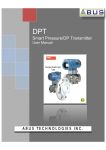
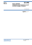
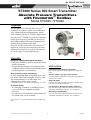
ST3000 Series 900 Smart Transmitter
Absolute Pressure Transmitters
with FOUNDATION™ fieldbus
Model STA923 / STA940
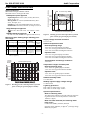
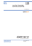
OVERVIEW
The ST3000 Series 900 with FOUNDATION™
fieldbus is an accurate, stable, and reliable pressure / differential pressure transmitter, which
fully complies with the 31.25 kbps voltage mode
FOUNDATION™ fieldbus. Its built-in AI function
blocks provide process variables to devices on
the Fieldbus and its PID control function block
enables process control in the field.
Since the ST3000 Series 900 is FOUNDATION™
registered, it can operate seamlessly with other
registered field devices as well as host systems
in a wide range of control applications.
FEATURES
Excellent stability and high performance
• Long-term stability is proven in 500,000 installations worldwide.
• Unique characterization and composite semiconductor sensors realize excellent temperature
and static pressure characteristics.
APPLICATION
Petroleum / Petrochemical / Chemical
For measuring pressures and liquid levels in pipes and
tanks.
Wide measuring range (rangeability)
Electric power / City gas / Other utilities
For measurement applications that require high degrees of
stability and accuracy.
A wide measuring range is available from a single model. This feature is highly effective in taking measurements over a wide range and
reducing the need for reserve units.
Pulp and paper
For lines that need transmitters resistant to chemical liquids, corrosive fluids and the like
* Model STA940: 35 to 3500 kPa (rangeability: 1 to 100)
A diverse lineup
Iron and steel / Nonferrous metal / Ceramics
For lines that require stable measurement under strictly
controlled (temperature, humidity, etc.) conditions
• A wide range of models is available to meet
user needs for low, standard, and high
pressures.
• A wide variety of corrosion-resistant materials
for wetted parts is also available.
Machinery / Shipbuilding
For lines that require stable measurement under strictly
controlled (temperature, humidity, etc.) conditions.
FOUNDATION™ is a registered trademark of the Fieldbus Foundation.
Specifications are subject to change without notice.
-1-
3rd Edition
No. SS2-STJ50F-0100
Azbil Corporation
Type of protection
JIS C0920 watertight: NEMA3 and 4X
JIS F8001 class 2 watertight: IEC IP67
FM Explosionproof approval
Explosionproof for Class I (Gas, steam), Division 1,
Group A, B, C, D
Dust-ignition for Class II (Inflammable dust), Division 1, Group E, F, G
Suitable for Class III (inflammable fiber), Division 1
Nonincendive for Class I, Division 2, Group A, B, C, D
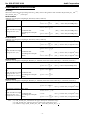
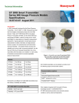
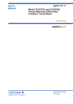
Working pressure P kPa {mmHg}
FUNCTIONAL SPECIFICATIONS
Unusable range
133.3
{1000}
Normal operating
range
101.3
{760}
53
{400}
ATEX Flameproof approval
-40
II 2 GD EEx d IIC T6 at -20 < Tamb < +60°C
Ambient temperature limits
0.01 to 3500 kPa abs
STA 35 to 3500 kPa abs 0 to 3500 kPa abs {0.1 mmHg abs to 5250 kPa abs
940 {0.35 to 35 kgf/cm2 abs} {0 to 35 kgf/cm2 abs} 35 kgf/cm2 abs} {52.5 kgf/cm2 abs}
See Figure 1, 2
Note) With PVC wetted parts, the maximum working pressure is 1.5
MPa {15 kgf/cm2}.
Operative limits
Other than SUS316
Normal operating range
-40 to 110°C for general purpose models
-10 to 75°C for oxygen and chlorine models
115 C
110 C
Operative limit
-50 to 115°C for general purpose models
-40 to 80°C for oxygen and chlorine models
0.13
Ambient humidity limits
5 to 100% RH
SUS316
0
Operative limit
-50 to 93°C for general purpose models
-40 to 80°C for oxygen and chlorine models
-30 to 80°C for models with digital indicators
Temperature ranges of wetted parts
1.0
0.013
{0.1} -50 -40
Normal operating range
-40 to 85°C for general purpose models
-10 to 75°C for oxygen and chlorine models
-20 to 70°C for models with digital indicators
Transportation and storage conditions
-50 to 85°C
Normal operating range
Operative limits
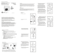
Working pressure P
10.0
80
Supply voltage and load resistance
9 to 32 V DC
Overload
Working
Resistant
Pressure Range
Value
0.01 to 104 kPa abs
STA 4 to 104 kPa abs
300 kPa abs
0 to 104 kPa abs
{0.1 to 780 mmHg abs}
923 {30 to 780 mmHg abs} {0 to 780 mmHg abs} See Figure 1, 2 {3.0 kgf/cm2 abs}
101.3
75
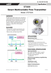
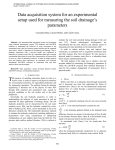
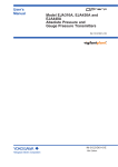
Figure 2 Working pressure and temperature of wetted
parts section (for general purpose models)
Measuring span / Setting range / Working pressure range
kPa abs
{mmHg}
1000.0
40
Temperature of wetted parts ( C)
NEPSI Flameproof approval
Ex d IIC T6 (with NEPSI Dust Ignition DIP DT T13)
Measuring Span Setting Range
-10 0
50
100
Stability against supply voltage change
± 0.005% FS/V
Temperature of wetted parts ( C)
Figure 1 Working pressure and temperature of wetted
parts section (for general purpose models)
Lightning protection
Peak value of voltage surge: 12 kV
Peak value of current surge: 1000 A
Optional specifications
Built-in indicating meter
The digital LCD indicator (optional) indicates engineering units and can be set freely between -19999 and
19999 (4.5 digits).
Bolts and nuts materials (for fastening meter
body cover)
Carbon steel (SNB7), SUS304, SUS630
(Pressure rating 7000 kPa {70 kgf/cm2} or flange rating)
Baked acrylic paint.
-2-
Azbil Corporation
No. SS2-STJ50F-0100
PHYSICAL SPECIFICATIONS
Corrosion-resistant finish
Corrosion-resistant finish
Materials
Corrosion-resistant paint (baked acrylic paint), fungusproof finish.
Fill fluid
Silicone oil for general purpose and high-temperature
vacuum models
Fluorine oil for oxygen and chlorine models
Corrosion-proof finish
Corrosion-proof paint (baked epoxy paint), fungusproof finish.
Center body
SUS316
Corrosion-resistant finish (silver paint)
Transmitter case is coated with silver paint in addition
to the above corrosion-resistant finish.
Transmitter case
Aluminum alloy
Oil free finish
The transmitter is shipped with oil-free wetted parts.
(The vent drain plug is coated with a small amount of
fluorine oil to prevent galling.)
Meter body cover
SCS14A (equivalent to SUS316) or SUSF316, PVC
For wetted parts
Long vent / Drain plugs
A longer (58 mm) drain than the standard (24 mm) can
be used for maintenance, process, and safety reasons.
Adapter flange (option)
Elbow
This is an adaptor for changing the electrical conduit
connection port from the horizontal to the vertical direction, if required by wiring conditions in the field. One or
two elbows may be used as needed.
SUS316 (diaphragm SUS316L)
Hastelloy C, Tantalum, SUS316L
Conformance to SI units
We deliver transmitters set to any SI units as specified.
FEP
SCS14A (equivalent to SUS316), PVC
Center body
Vents and plugs
SUS316, PVC
Gaskets
Finish
Baked acrylic paint
Housing light beige (Munsell 4Y7.2/1.3)
Cap dark beige (Munsell 10YR4.7/0.5)
Weight
Approx. 6.8 kg
INSTALLATION
Electrical connection
1/2NPT internal thread
Grounding
Resistance 100 Ω max
Mounting
Can be installed on a 2 inch horizontal or vertical pipe
(can be directly mounted on the process pipe)
Process connection
Rc1/2, 1/2NPT internal thread and Rc1/4, 1/4NPT internal
thread
-3-
No. SS2-STJ50F-0100
Azbil Corporation
PERFORMANCE SPECIFICATIONS
Accuracy
Shown for each item is the percentage ratio for χ (kPa), which is the greatest value of either XD_SCALE_EU_100 (*1),
XD_SCALE_EU_0 (*2), or the span.
Model STA923
(Material of wetted parts: Diaphragm; SUS316L, Others; SUS316)
Accuracy (*3)
± 0.15%
12
± ⎛ 0.05 + 0.1 × ------⎞ %
⎝
χ⎠
Temperature characteris- Zero shift:
tics
(Shift from the set range)
Combined shift:
Change of 55°C (*3)
(including zero and span
shifts)
(For χ < 12kPa abs{90 mmHg abs})
12
± ⎛⎝ 0.35 + 0.75 × ------⎞⎠ %
χ
± 1.2%
(For χ ≥ 12kPa abs{90 mmHg abs})
12
± ⎛⎝ 0.35 + 0.85 × ------⎞⎠ %
χ
(For χ < 12kPa abs{90 mmHg abs})
Model STA940
(Material of wetted parts: Diaphragm; SUS316L, Others; SUS316)
Accuracy (*3)
± 0.15%
350
± ⎛⎝ 0.05 + 0.1 × ---------⎞⎠ %
χ
Temperature characteris- Zero shift:
tics
(Shift from the set range)
Combined shift:
Change of 55°C (*3)
(including zero and span
shifts)
(For χ ≥ 12kPa abs{90 mmHg abs})
(For χ ≥ 350kPa abs{3.5 kgf/cm2 abs})
(For χ < 350kPa abs{3.5 kgf/cm2 abs})
350
± ⎛ 0.25 + 0.75 × ---------⎞ %
⎝
χ ⎠
± 1.2%
(For χ ≥ 350kPa abs{3.5 kgf/cm2 abs})
12
± ⎛⎝ 0.35 + 0.85 × ------⎞⎠ %
χ
(For χ < 350kPa abs{3.5 kgf/cm2 abs})
Model STA923
(Material of wetted parts: Diaphragm; Hastelloy C, Tantalum, SUS316L Others; Hastelloy C, Tantalum, SUS316L)
Accuracy (*3)
± 0.35%
(For χ ≥ 12kPa abs{90 mmHg abs})
12
± ⎛ 0.25 + 0.1 × ------⎞ %
⎝
χ⎠
Temperature characteris- Zero shift:
tics
(Shift from the set range)
Combined shift:
Change of 30°C (*3)
(including zero and span
(Range from -5 to 55°C)
shifts)
(For χ < 12kPa abs{90 mmHg abs})
24
± ⎛ 0.15 + 1.85 × ------⎞ %
⎝
χ⎠
24
± ⎛ 0.55 + 1.85 × ------⎞ %
⎝
χ⎠
Model STA940
(Material of wetted parts: Diaphragm; Hastelloy C, Tantalum, SUS316L Others; Hastelloy C, Tantalum, SUS316L)(
Accuracy (*3)
± 0.35%
(For χ ≥ 350kPa abs{3.5 kgf/cm2 abs})
350
± ⎛⎝ 0.25 + 0.1 × ---------⎞⎠ %
χ
Temperature characteris- Zero shift:
tics
(Shift from the set range)
Combined shift:
Change of 30°C (*3)
(including zero and span
(Range from -5 to 55°C)
shifts)
Note
(For χ < 350kPa abs{3.5 kgf/cm2 abs})
350
± ⎛⎝ 0.25 + 0.75 × ---------⎞⎠ %
χ
± 1.5%
(For χ ≥ 350kPa abs{3.5 kgf/cm2 abs})
350
± ⎛⎝ 0.35 + 1.15 × ---------⎞⎠ %
χ
(For χ < 350kPa abs{3.5 kgf/cm2 abs})
(*1): XD_SCALE_EU_100 denotes the upper limit of the calibration range.
(*2): XD_SCALE_EU_0 denotes the lower limit of the calibration range.
(*3): Within a range of XD_SCALE_EU_100 > 0 and XD_SCALE_EU_0 > 0.
-4-
Azbil Corporation
No. SS2-STJ50F-0100
FIELDBUS SPECIFICATIONS
Block supported by the S900
Max.
execution time
msec.
Name of block
Number of
block
Resource block
1
The Resource Block (RB) maintains overall resources of
the S900.
-
Transducer block
1
The Transducer Block (XB) interfaces with the sensing element of the S900, converts the measured value into specified engineering unit, and sends it to the AI Function
Block.
-
AI Function Block
2
The AI Function Block (AI FB) accepts an analog input
signal from the XB, scales it, detects alarm conditions, and
provides it in a uniform format on the Fieldbus network.
75
Diagnostics Block
1
The Diagnostics Block (DB) is Azbil Corporation’s proprietary block which provides the result of self-diagnostics of
the S900.
-
1
The PID Function Block (PID FB) accepts a process variable (PV) from an AI Function Block on the Fieldbus network, calculates the valve position using the PID
algorithm, and sends a new valve output signal to the AO
Function Block.
125
PID Function Block
Description
VCR structure
The S900 has 16 VCRs (Virtual Communication Relationships), of which the first one is dedicated to the SMIB/NMIB as
defined by Foundation Fieldbus specifications. The rest of the VCRs are fully configurable. Their default configurations
are shown below:
VCR No.
Configuration
VCR No.
Configuration
1
QUB (Server) for NIMIB/SMIB
9
QUU (Source)
2
BNU (Subscriber)
10
QUU (Source)
3
BNU (Subscriber)
11
QUU (Source)
4
BNU (Subscriber)
12
QUB (Server)
5
BNU (Subscriber)
13
QUB (Server)
6
BNU (Publisher)
14
QUB (Server)
7
BNU (Publisher)
15
QUB (Server)
8
QUU (Source)
16
QUB (Server)
Network parameters
The following table lists the key parameter values that affect the interoperability of the Fieldbus devices. The LAS must
be configured to satisfy these parameters. If other devices on the same Fieldbus network require a greater number for
them, the greater number must be used. This however will degrade network performance.
Symbol
V (ST)
Parameter name
Range of value
Slot Time
4 to 100
V (MID)
Minimum Interframe Gap
10 to (V (MRD) - 1) × V (ST), less than 120 inclusive.
V (MRD)
Maximum Response Delay
V (MRD) × V (ST) shall be greater than 20 and
V (MRD) shall be less than 11, inclusive.
T1
SM step timer
96000 (3 seconds)
T2
SM set address sequence
timer
1920000 (60 seconds)
T3
SM set address wait timer
480000 (15 seconds)
Note)
• An LAS requires parameters other than those listed here for operation. Please refer to the user’s manual that is provided with your LAS
device.
• The T3 must be set between 15 seconds and 60 seconds.
-5-
No. SS2-STJ50F-0100
Azbil Corporation
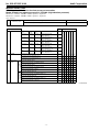
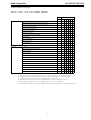
MODEL SELECTION
ST3000 series 900 electric absolute pressure transmitter
Model STA923 (low absolute pressure) / STA940 (high absolute pressure)
Model No.: STA923 - I II III - 00000 - Option I - Option II
Model No.: STA940 - I II III - 00000 - Option I - Option II
Basic Model No.
Measuring span
4.0 to 104 kPa abs (30 to 780 mmHg abs.) *13
35 to 3500 kPa abs (0.35 to 35
kgf/cm2
abs.) *14
Selection I
Meter body Adapter
cover
flange
Fill fluid
III Process connection
Vent/drain Wetted parts of center body
plugs
-
SCS14A*1
SCS14A* SUS316
1
Diaphragm:SUS316L
Others: SUS316
E
SCS14A*1
SCS14A* SUS316
1
Diaphragm: Hastelloy C
Others: Hastelloy C
F
SCS14A*1
SCS14A* SUS316
1
Diaphragm: Tantalum
Others: Tantalum
H
SCS14A*1
SCS14A* SUS316
1
Diaphragm:SUS316L
Others: SUS316L
U
PVC
PVC
PVC
Diaphragm: Hastelloy C
Others: Hastelloy C *8
M
PVC
PVC
PVC
Diaphragm: Tantalum
Others: Tantalum *8
P
Material code
E
F
H U M P
1
a a a a a a
For oxygen service (Fluorine oil) *3
2
a a a a a a
For chlorine service (Fluorine oil) *3
5
Regular type (Silicone oil)
Front
connection
II
Code
Material
Top or bottom
connection
I
STA923
STA940
a
a
Rc1/2 with adapter flange
L
a
1/2NPT internal thread with adapter flange
G
a
Rc1/4 with adapter flange
D
a
1/4NPT internal thread with adapter flange
A
a
1/4NPT internal thread on head
B
a
Rc1/2 with adapter flange *9
Q
a a a a a
1/2NPT internal thread with adapter flange *9
R
a a a a a
Rc1/4 with adapter flange *9
S
a a a
1/4NPT internal thread with adapter flange *9
T
a a a
1/4NPT internal thread on head *9
U
a a a
(Continued)
-6-
Azbil Corporation
No. SS2-STJ50F-0100
(Continued from previous page)
Model No.: STA923 - I II III - 00000 - Option I - Option II
Model No.: STA940 - I II III - 00000 - Option I - Option II
Code
Options I
Material code
F
H
U M P
-
E
X
a a a a a a
Built-in indicating smart meter (0 to 100% liner scales)
P
a a a a a a
Built-in indicating smart meter (engineering unit scales)
R
a a a a a a
SUS304 bolt and nuts material
W
a a a a a a
SUS630 bolt and nuts material
U
a a a a
Corrosion-resistant finish
A
a a a a a a
Corrosion-proof finish
B
a a a a a a
Corrosion-resistant finish, silver paint
D
a a a a a a
Oil Free finish
K
a a a a a a
Long vent/drain plugs
J
a a a a
FM Explosion proof
3
a a a a a a
ATEX Flameproof
6
a a a a a a
No options
Options II
Note)
*1
*3
*8
*9
No option
XX
a a a a a a
Water free finish (with oil free finish)
A7
a a a a a a
NEPSI Flameproof
C1
a a a a a a
Custom calibration
C7
a a a a a a
FOUNDATION™
D6
a a a a a a
One elbow
E1
a a a a a a
Two elbows
E2
a a a a a a
Mounting bracket
E9
a a a a a a
Side vent/drain top
F1
a
Side vent/drain bottom
F2
a
Material certificate
H2
a a a a a a
Fieldbus communication stack BASIC class (used with option D6) *33
L1
a a a a a a
SI unit
U1
a a a a a a
fieldbus *33
SCS14A (equivalent SUS316) or SUSF316
In case “for oxygen or chlorine (fluorine oil) service” is used, “oil free finish - code K” must be selected.
SUS304 bolts and nuts material (-W) must be selected when PVC meterbody cover is selected (-M or -P)
Applicable for wetted parts of center body material; Hastelloy C or Tantalum
*13 Specify range in abs. pressure. Correct: 0 to 500 mmHg abs. Incorrect: -700 mmHg to 1 kgf/cm2
*14 Specify range in abs. pressure. Correct: 0 to 3 kgf/cm2 abs. Incorrect: -1 to 2 kgf/cm2 abs.
*33 “FOUNDATION™ fieldbus - code D6” and “Fieldbus communication stack BASIC class - code L1” must be selected.
-7-
No. SS2-STJ50F-0100
Azbil Corporation
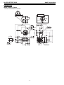
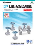
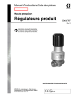
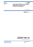
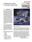
DIMENSIONS
Model STA923 / STA940
Process connection: Front side
-8-
–
TEST
+
Rotational lock
METER
+
L
–
SIGNEL
–
+
Terminal connection
(M4 Screw)
Azbil Corporation
No. SS2-STJ50F-0100
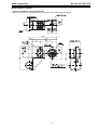
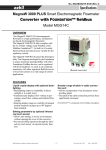
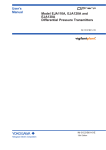
Model STA923 / STA940
Process connection: Top or bottom side
*Meter unit inside of transmitter can be rotated for the following installation
-9-
No. SS2-STJ50F-0100
Azbil Corporation
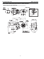
Model STA923 / STA940 (Wetted parts materials: Tantalum, SUS316L)
Process connection: Top or bottom side
*Meter unit inside of transmitter can be rotated for the following installation.
M4 External
ground screw
Rotational lock
- 10 -
–
TEST
+
METER
+
L
–
SIGNEL
–
+
Terminal connection
(M4 Screw)
Note
1st Edition: Issued in May 2002
3rd Edition: Issued in July 2012