1
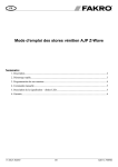
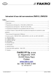
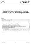
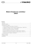
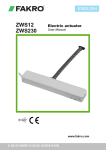
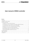
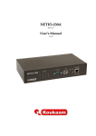
GB
ZWS12, ZWS230 motors user manual
Spis treści
1 Safety rules .......................................................................................................................................2
2 Description .......................................................................................................................................3
3 Quick start ........................................................................................................................................4
4 Device programming ........................................................................................................................5
5 Interoperability of devices different manufacturers..........................................................................6
6 Including ZWS actuator into a third-party network..........................................................................6
7 Reset (factory default).......................................................................................................................6
8 Special functions...............................................................................................................................6
9 Manual operating ..............................................................................................................................7
10 Technical parameters ......................................................................................................................7
11 Signalling description – LEDs........................................................................................................8
12 WARRANTY..................................................................................................................................8
FAKRO PP Sp. z o.o.
144A Węgierska St
33-300 Nowy Sacz
Poland
www.fakro.com
tel. +48 18 444 0 444
fax. +48 18 444 0 333
10.08.23 NC814
1/8
©2010, FAKRO
1 Safety rules
Please read carefully the instructions below before proceeding to the device installation so
as to prevent electric shock, injury, etc.
When installing the mechanical motor, it is necessary to observe the following
recommendations:
● Above all, follow the safety rules. The use of electric motors for roof window operating is
connected with a risk of injury. Although, the motor is equipped with an overload switch,
the forces which operate here are strong enough to cause injury.
● If the window equipped with an electric motor is easily accessible, e.g. the lower window
edge is situated lower than 2.50m above the floor level, then special safety measures should
be adopted so as to prevent health hazards.
● After unpacking, check the motor elements for any signs of mechanical damage.
● Installation should be performed by a qualified person in accordance with manufacturer
instructions.
● Before connecting the motor, make sure that the power voltage corresponds with motor
voltage specified on the data plate.
● Connect the motor and verify its correct functioning by performing one full working cycle
without any load (two-core cable – 12V DC motor, three-core cable – 230V AC). Leave the
chain protruding by approximately 5cm.
● Plastic containers used for packing should be stored out of children reach as they may be a
potential source of danger.
● The motor should be used according to its intended design. The FAKRO Company shall
not be responsible for any consequences being the result of improper motor use.
● Any activities relating to cleaning, adjustment or dismantling the motor should be preceded
with disconnecting the power supply.
● The motor cannot be washed using solvent-based substances or open stream of water (do
not immerse in water).
● Any repairs of the motor should be carried out by service authorised by the manufacturer
● Electric wires supplying electricity to the power source must have suitable area (2x1mm2).
Permissible cable length for the mentions area is 30mb.
● The motor has been designed for installation inside the room.
● The motor cannot be used as a mechanism for operating the sashes of smoke ventilation
windows (FAKRO window).
WARNING!!!
Danger of crashing. While closing, the motor exerts the force of 250N (app. 25kg).
10.08.23 NC814
2/8
©2010, FAKRO
2 Description
The ZWS12, ZWS230 motors are intended for operating FAKRO roof windows and
adapted for cooperating with wireless remote control systems offered by FAKRO and by others
manufacturers offering products with logo Z-Wave. The ZWS motors are equipped with a twoway “Z-Wave” communication radio module. For communication, the Z-Wave exploits radio
wave frequency of 868.43MHz. ZWS motors are Security Enabled products.
Security Enabled Z-Wave Controller must be used in order to fully utilize ZWS.
The motor functionality is anyway identical when included as a secure and non-secure device.
The ZWS motors are equipped with two limits:
• limit switch at maximum chain travel position,
• overload limit at folded chain position.
In order to be able to operate FAKRO roof windows with the use of ZWS motors, they must be
installed according to the picture installation manual included in the product package.
Subsequently, the motors should be programmed to work with one of the controllers (e.g.
ZWP15 remote control, ZWK15, ZWK1 keyboard) offered by FAKRO – see section 3.
In Figure 1 there is presented a general view of the ZWS motor with description of available
buttons and signals.
4
3
2
1
C
B
Power cable
A
1.
2.
3.
4.
Programming button
Network status (LED)
Manual operating button
Motor operating status (LED)
Section
ZWS12
ZWS230
A
262 mm
362 mm
B
33.5 mm
33.5 mm
C
47 mm
47 mm
Figure 1: ZWS12, ZWS230 motors
10.08.23 NC814
3/8
©2010, FAKRO
3 Quick start
To be able to operate ZWS12, ZWS230 motors by means of one of the controllers
i.e. ZWK1, ZWK15, ZWP15, offered by FAKRO it is necessary to:
1. Ad the device (using “INCLUDE” function) to the selected Controller. A model
procedure is presented in Figure 2;
2. Associate the device with the selected pair of buttons on the Controller (using
“ASSOCIATE” function). A model procedure is presented in Figure 3.
INCLUDE
x1
x1
1. Press the “In/Ex” button on the controller once. The
controller is signalizing readiness for adding a new
device to the network (Ext, diodes on for 10 sec.).
2. Press the programming button on the device
Figure 2: Adding ZWS motor to Z-Wave network.
ASSOCIATE
1
x1
x1
2
x1
1. Press the buttons within 1 sec:
- „In/Ex” (1) once and then
- button from this pair of buttons which are to operate
the device (e.g. 2).
Controller is signalising readiness for associating the
device with a pair of buttons on the controller (three
diodes (1,2,3) on for 10 sec.)
2. Press the programming button.
Figure 3: Associating ZWS motor with selected pair of controller buttons
10.08.23 NC814
4/8
©2010, FAKRO
4 Device programming
Detailed programming description is included in the user's manual for each particular
controller. For assigning devices to controller(s), the “Programming button” should be used
(Figure 1. No.1), which is for:
• Device adding (“INCLUDE” function) or device removing (“EXCLUDE” function)
to/from the Z-Wave network;
• Device assigning (“ASSOCIATE” function) or device deleting (“DELETE” function)
to/from selected controller group of buttons. Device deleted from group of buttons still is
a part of Z-wave network until “EXCLUDE” function is executed.
Other manufacturers may apply different programming sequences.
EXCLUDE
x2
x1
1. Press the „In/Ex” button twice within 1 sec. The
controller is signalising readiness for device deleting from
the network (two middle diodes on for 10 sec.)
2. Press the programming button on the device
Figure 4: Removing ZWS motor from Z-Wave network.
DELETE
1
x2
x1
2
x1
1. Press the buttons within 1.5 sec.:
- „In/Ex”(1) twice and then
- button form this pair of buttons which
operates the device being deleted (e.g. 2).
Controller is signalizing readiness for device
deleting (three diodes (2,3,4) on for 10 sec.)
2. Press the programming button on the device
Figure 5: Deleting ZWS motor from selected pair of controller button.
10.08.23 NC814
5/8
©2010, FAKRO
5 Interoperability of devices different manufacturers
The Z-Wave allows you to integrate devices from different manufacturers working in different functional groups, such
as light, heating, home automation ect. The Z-Wave network devices act as repeaters which increases the range of radio waves. The
more devices on the network, the more stable and resistant to distortion is this network.
6 Including ZWS actuator into a third-party network
Start the “INCLUDE” function on the controller which is able to perform inclusion procedure for desired network and press
“Programming” button on the ZWS to be included.
Note:
For information on handling or initiation the inclusion function of products of
another manufacturers, please read the documents of the respective manufacturer.
7 Reset (factory default)
Sometimes it is necessary to reset ZWS to the factory settings and deleting all network information as well as group associations. For
resetting, a primary controller (able to include/exclude) is needed. For ZWS Reset function is synonymous with “EXCLUDE”
function from the network
Note:
A successful reset of the ZWS is signalled by network status diode continuous glow
8 Special functions
“PROTECTION” - used to protect a device against unintentionally control by e.g. a child. Three levels can be set by any controller
supporting this functionality.
Unprotected – motor can be operated manually and remote as well
Protection by sequence – motor can be only operated manually by means of local button (see Figure 1.) with sequence (three short
hit the button)
No operation possible – both control (manual, remote) locked.
Note:
The description for activation and deactivation of the protection function is
described in the user manual of the controllers supporting this function.
“RETURN ROUTE ASSIGNING” - depending on version actuator can be equipped with rain sensor input. In such case it is
possible to link this actuator with other actuators which have not rain sensor functionality. In this case it is necessary to initiate
"ASSIGN" function by Controller.
Standard procedure which can vary for different controllers is:
Start "ASSIGN" function – press (1 sec) programming button on actuator without rain sensor – press (1 sec) programming button on
actuator with rain sensor.
Note:
For information on handling or initiation the assign function of products of
another manufacturers, please read the documents of the respective manufacturer.
“All ON or All OFF” - it is possible to define if device should respect All close (OFF) or All Open (ON) command.
Note:
The description for activation and deactivation of the protection function is
described in the user manual of the controllers supporting this function.
“SECURITY”
ZWS motors are Security Enabled products. The security provides confidential communication between nodes in network.
Note:
Security Enabled Z-Wave Controller must be used in order to fully utilize ZWS.
10.08.23 NC814
6/8
©2010, FAKRO
9 Manual operating
The “Manual operating” button makes it possible to operate the motor right after
connecting the power supply. Manual operating works in sequential mode, i.e. start, stop, start
in opposite direction, stop – etc...
1. First pressing of the button after connecting the power supply will cause the motor chain
to unfold.
2. Second pressing the button, stops the motor
3. Third pressing the button starts the motor in the opposite direction.
Note:
Watch the LED showing the status of devices on the network. Blinking LED indicates the status of
protection state ( see section 7) and may mean that the control of the device is not possible
10 Technical parameters
Technical Parameters
Parameter
ZWS12
ZWS230
Chain reach
240 mm
360 mm
Output power
9W
15W
Rated current
0.72 A
0.12 A
Standby current
0.03 A
0.03 A
Current limit
YES
YES
Chain unfolding
rate
7.5 mm
9.7 mm
Chain pushing
force
200 N
200 N
Closing force
200 N
200 N
Working
temperature
(-10oC) do (65oC)
(-10oC) do (65oC)
Power cable
10.08.23 NC814
2 x 0.75 mm2 (0,4 m) 3 x 0.75 mm2 (1,5 m)
Power voltage
12V DC
90 - 230V AC
Weight
0.850 kg
0.940 kg
7/8
©2010, FAKRO
11 Signalling description – LEDs
Light signalling
(LED)
ZWS12, , ZWS230
No. 3 – Motor operating status
No. 4 – Network status
The device is in protected mode. Both
Overload limit has been activated while (Protected by sequence and no
Diode is on for 2-3 sec.
pulling the chain - the window is closed
operation possible) levels are signalized
in the same way.
Diode is on
continuously
The device has not been associated with
any network. This LED always comes
on after connecting power supply to a
brand new motor. It is switched off
after associating the device with
network.
-
12 WARRANTY
The manufacturer guarantees correct device functioning. It also undertakes to repair
or replace faulty device if its defects result from material or structural faults. The warranty
period is 24 months form the date of purchase, fulfilling the following conditions:
● Installation has been performed by an authorised individual, as per manufacturer
recommendations.
● Seals remain intact and no unauthorised structural changes have been made.
● The device has been used in accordance with its intended use as per user manual.
● Damage is not a result of improperly made electrical system or atmospheric phenomena.
● The manufacturer is not liable for damage which occurred as a result of improper use or
mechanical damage.
In case of failure, the device must be submitted for repair with a Warranty Card. Defects
revealed within the warranty period will be removed free of charge no longer than 14 days after
accepting the product for repair. Warranty and post-warranty repairs are performed by the
manufacturer i.e. FAKRO PP. Sp. z o.o..
Quality Certificate:
Device
Model............................................................................................................................................
Serial Number...............................................................................................................................
Seller.............................................................................................................................................
Address...........................................................................................................................................
Date of purchase............................................................................................................................
...............................................................................................................
Signature (stamp) of installing person
10.08.23 NC814
8/8
©2010, FAKRO