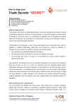
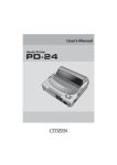
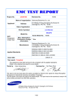
1
Report No.: TS13080027-EME
Page 1 of 51
EMC
TEST REPORT
Report No.: TS13080027-EME
Model No.: RVTT-10711 Titanium TXF3.0
RVTT-10411 Titanium TX2.0
Issued Date: Oct. 24, 2013
Applicant:
Tung Keng Enterprise Co., Ltd
No. 1, Lane 160, Sec. 2, Tan-Fu Road, Tan-Tzu Dist.,
Taichung, Taiwan
Test Method/ Standard: EN 55014-1: 2006+A1: 2009+A2: 2011
EN 61000-3-2: 2006+A1: 2009 +A2: 2009
EN 61000-3-3: 2008
EN 55014-2: 1997+A1: 2001+A2: 2008
Test By:
Intertek Testing Services Taiwan Ltd.,
Hsinchu Laboratory
No. 11, Lane 275, Ko-Nan 1 Street, Chia-Tung Li,
Shiang-Shan District, Hsinchu City, Taiwan
It may be duplicated completely for legal use with the allowance of the applicant. It shall
not be reproduced except in full, without the written approval of Intertek Laboratory. The
test result(s) in this report only applies to the tested sample(s).
The test report was prepared by:
Sign on File
Candy Liu/ Assistant
These measurements were taken by:
Sign on File
Wen Chen / Engineer
The test report was reviewed by:
Name Rico Deng
Title Senior Engineer
Report No.: TS13080027-EME
Page 2 of 51
Table of Contents
1. General Information ............................................................................................................... 4
1.1 Identification of the EUT ................................................................................................. 4
1.2 Adapter information ......................................................................................................... 4
1.3 Additional information about the EUT............................................................................. 4
2. Test Summary......................................................................................................................... 5
3. Test Specifications.................................................................................................................. 6
3.1 Standards .......................................................................................................................... 6
3.2 Test Facility accreditation ................................................................................................ 6
3.3 Performance criteria ......................................................................................................... 7
3.4 Mode of operation during the test .................................................................................... 8
3.5 Peripherals equipment ...................................................................................................... 8
4. Conducted Emission Test ....................................................................................................... 9
4.1 Test Procedure .................................................................................................................. 9
4.2 Test Equipment................................................................................................................. 9
4.3 Conducted Emission Limit............................................................................................. 10
4.4 Uncertainty of Conducted Emission .............................................................................. 10
4.5 Conducted Emission Data .............................................................................................. 11
5. Discontinuous Disturbance Voltage ..................................................................................... 15
5.1 Test Procedure ................................................................................................................ 15
5.2 Test Equipment............................................................................................................... 15
5.3 Test Results..................................................................................................................... 16
6. Radiated Emission Test ........................................................................................................ 18
6.1.1 Test Procedure from 30 MHz to 1000 MHz................................................................ 18
6.1.2 Test Equipment............................................................................................................ 19
6.1.3 Radiated Emission Limit............................................................................................. 19
6.1.4 Uncertainty of Radiated Emission............................................................................... 19
6.1.5 Radiated Emission Test Data from 30 MHz to 1000 MHz ......................................... 20
7. Harmonics Test..................................................................................................................... 24
8. Voltage Fluctuations-Flicker Test......................................................................................... 25
8.1 Test Procedure ................................................................................................................ 25
8.2 Test Equipment............................................................................................................... 25
8.3 Uncertainty of Flicker .................................................................................................... 25
8.4 Test result ....................................................................................................................... 26
9. Electrostatic Discharge Immunity Test ................................................................................ 27
9.1 Purpose ........................................................................................................................... 27
9.2 Test Set-Up ..................................................................................................................... 27
9.3 Test Specification ........................................................................................................... 27
9.4 Test Equipment............................................................................................................... 27
9.5 Test Result ...................................................................................................................... 28
Report No.: TS13080027-EME
Page 3 of 51
10. Radiated, Radio-Frequency, Electromagnetic Field Immunity Test .................................. 30
10.1 Purpose ......................................................................................................................... 30
10.2 Test Set-Up ................................................................................................................... 30
10.3 Test Specification ......................................................................................................... 30
10.4 Test Equipment............................................................................................................. 31
10.5 Generation of the Electromagnetic Field ..................................................................... 31
10.6 Test Results................................................................................................................... 31
11. Electrical Fast Transient/Burst Immunity Test ................................................................... 33
11.1 Purpose ......................................................................................................................... 33
11.2 Test Set-Up ................................................................................................................... 33
11.3 Test Specification ......................................................................................................... 33
11.4 Test Equipment ............................................................................................................. 33
11.5 Test Results................................................................................................................... 34
12. Surge Immunity Test.......................................................................................................... 36
12.1 Purpose ......................................................................................................................... 36
12.2 Test Set-Up ................................................................................................................... 36
12.3 Test Specification ......................................................................................................... 36
12.4 Test Equipment. ........................................................................................................... 36
12.5 Test Results................................................................................................................... 37
13. Immunity to Conducted Disturbances, Inducted by Radio-Frequency Fields ................... 39
13.1 Purpose ......................................................................................................................... 39
13.2 Test Set-Up ................................................................................................................... 39
13.3 Test Specification ......................................................................................................... 39
13.4 Test Equipment............................................................................................................. 40
13.5 Generation and Calibration of the Disturbance Signal................................................. 40
13.6 Test Results................................................................................................................... 41
14. Voltage Dips, Short Interruptions and Voltage Variations Immunity Test.......................... 42
14.1 Purpose ......................................................................................................................... 42
14.2 Test Set-Up ................................................................................................................... 42
14.3 Test Specification ......................................................................................................... 42
14.4 Test Equipment............................................................................................................. 43
14.5 Generation of the Disturbance Signal .......................................................................... 43
14.6 Test Result .................................................................................................................... 43
Appendix A1: External photo of EUT(RVTT-10411 Titanium TX2.0) ................................... 46
Appendix A2: External photo of EUT(RVTT-10711 Titanium TXF3.0) ................................. 48
Appendix A3: External photo of adapter.................................................................................. 51
Report No.: TS13080027-EME
Page 4 of 51
1. General Information
1.1 Identification of the EUT
Product:
Elliptical
Model No.:
RVTT-10711 Titanium TXF3.0, RVTT-10411 Titanium TX2.0
Rated Power:
DC 30 V from adapter
Power Cord:
2C × 0.75mm2 × 0.5 meter unshielded cable
Sample receiving date:
Aug. 05, 2013
Sample condition:
Workable
Testing date:
Aug. 13, 2013 ~ Oct. 21, 2013
Note 1: This report is for the exclusive use of Intertek's Client and is provided pursuant to the
agreement between Intertek and its Client. Intertek's responsibility and liability are
limited to the terms and conditions of the agreement. Intertek assumes no liability to
any party, other than to the Client in accordance with the agreement, for any loss,
expense or damage occasioned by the use of this report. Only the Client is
authorized to permit copying or distribution of this report and then only in its
entirety. Any use of the Intertek name or one of its marks for the sale or
advertisement of the tested material, product or service must first be approved in
writing by Intertek. The observations and test results in this report are relevant only
to the sample tested. This report by itself does not imply that the material, product,
or service is or has ever been under an Intertek certification program.
Note 2: The test report only allows to be revised within three years from its original issued
date unless further standard or the requirement was noticed.
Note 3: When determining the test conclusion, the Measurement Uncertainty of test has been
considered.
1.2 Adapter information
The EUT will be supplied with a power supply from below list:
No.
Brand
Model no.
Adapter
Fuyuang
FY3002500
Specification
I/P: 100-240VAC, 50/60Hz, 200VA
O/P: 30VDC, 2.5A
1.3 Additional information about the EUT
The customer confirmed Model RVTT-10711 Titanium TXF3.0 and RVTT-10411 Titanium
TX2.0 are different in the appearance.
For more detail features, please refer to user's Manual.
Report No.: TS13080027-EME
Page 5 of 51
2. Test Summary
Emission
Standard
EN 55014-1: 2006
+A1:2009+A2: 2011
Test Type
Result
Remarks
Conducted Test
PASS
Meet the requirements
Discontinuous disturbance
voltage
PASS
Meet the requirements
Radiated Emission
PASS
Meet the requirements
N/A
N/A
PASS
Meet the requirements
EN 61000-3-2: 2006
Harmonic current emissions
+A1: 2009 +A2: 2009
EN 61000-3-3: 2008
Voltage fluctuation & flicker
Immunity
(EN 55014-2: 1997+A1: 2001+A2:2008)
Standard
Test Type Performance Criteria
Result
IEC 61000-4-2: 2008
ESD
Criterion B
PASS
IEC 61000-4-3: 2010
RS
Criterion A
PASS
IEC 61000-4-4: 2011
EFT
Criterion B
PASS
IEC 61000-4-5:2008
Surge
Criterion B
PASS
IEC 61000-4-6: 2008
CS
Criterion A
PASS
IEC 61000-4-11: 2004 Dip
1. Interruptions reductionPerformance Criterion C
2. 30% reductionPerformance Criterion C
3. 60% reductionPerformance Criterion C
Remark: The EUT is category IV product.
PASS
Meets the requirements of
Performance Criterion B
Meets the requirements of
Performance Criterion A
Meets the requirements of
Performance Criterion A
Meets the requirements of
Performance Criterion A
Meets the requirements of
Performance Criterion A
Meets the requirements of
Voltage Dips:
1. Interruptions reductionPerformance Criterion A
2. 30% reduction- Performance
Criterion A
3. 60% reduction- Performance
Criterion A
Report No.: TS13080027-EME
Page 6 of 51
3. Test Specifications
3.1 Standards
EN 55014-1: 2006+A1:2009+A2: 2011 Electromagnetic compatibility ─ Requirements
for household appliances, electric tools and similar apparatus─ Part 1: Emission ─
Product family standard
EN 61000-3-2: 2006+A1: 2009 +A2: 2009 Electromagnetic compatibility ─ Part 3. Limits.
Section 2. Limits for harmonic current emissions (equipment input current ≤ 16 A per phase)
EN 61000-3-3: 2008 Electromagnetic compatibility ─ Part 3. Limits
Section 3. Limitation of voltage fluctuations and flicker in low-voltage supply systems for
equipment with rated current ≤ 16 A
EN55014-2: 1997+A1: 2001+A2:2008 Electromagnetic compatibility ─ requirements for
household appliances, electric tools and similar apparatus ─Part 2: Immunity ─ Product
family standard
3.2 Test Facility accreditation
Intertek Testing Services Taiwan Ltd., Hsinchu Laboratory is accredited in respect of
laboratory and the accreditation criterion is ISO/IEC 17025: 2005.
Certification
Accreditation
Certificate
Site Filling Code :
Bureau
Code
Accreditation Criteria
TAF
0597
ISO/IEC 17025
BSMI
SL2-IS-E-0024
SL2-IN-E-0024
SL2-A1-E-0024
SL2-R2-E-0024
SL2-R1-E-0024
SL2-L1-E-0024
ISO/IEC 17025
FCC
93910
IC
2042D-1, 2042D-2
Test facility list
& NSA Data
Test facility list
& NSA Data
R-1534
C-1618
Test facility list
VCCI
T-1586
& NSA Data
G-49
Note 1: Each certificate can be refer to attachment certification.pdf.
Note 2: Each certificate are within the valid calibration period.
Report No.: TS13080027-EME
Page 7 of 51
3.3 Performance criteria
A functional description and a definition of performance criteria, during or as a consequence
of the EMC testing, shall be provided by the manufacturer and noted in the test report, based
on the following criteria.
Criterion A:
The apparatus shall continue to operate as intended during the test. No degradation of
performance or loss of function is allowed below a performance level (or permissible loss of
performance) specified by the manufacturer, when the apparatus is used as intended. If the
minimum performance level or the permissible performance loss is not specified by the
manufacturer, then either of these may be derived from the product description and
documentation, and from what the user may reasonably expect from the apparatus if used as
intended.
Criterion B:
The apparatus shall continue to operate as intended after the test. No degradation of
performance or loss of function is allowed below a performance level (or permissible loss of
performance) specified by the manufacturer, when the apparatus is used as intended. During
the test, degradation of performance is allowed, however, no change of actual operating state
or stored data is allowed. If the minimum performance level or the permissible performance
loss is not specified by the manufacturer, then either of these may be derived from the product
description and documentation, and from what the user may reasonably expect from the
apparatus if used as intended.
Criterion C:
Temporary loss of function is allowed, provided the function is self- recoverable or can be
restored by the operation of the controls, or by any operation specified in the instructions for
use.
Report No.: TS13080027-EME
Page 8 of 51
3.4 Mode of operation during the test
EUT connects to adapter by AC source (90~264Vac, 50/60Hz) via to AMN system.
Press the start button on console, and tread elliptical until test is finished. During the test, we
keep RPM higher than 40.
All test modes were verified and shown the final test data in report as below table.
For model: RVTT-10411 Titanium TX2.0
Test Items
Conducted Emission
Emission
Discontinuous disturbance voltage
Radiated Emission
Flicker
Immunity
For model: RVTT-10711 Titanium TX3.0
Test Items
Conducted Emission
Emission
Discontinuous disturbance voltage
Radiated Emission
Flicker
Immunity
Test Mode
RPM Function Work
Test Mode
RPM Function Work
Test Voltage
264Vac, 50Hz
264Vac, 50Hz
230Vac, 50Hz
230Vac, 50Hz
230Vac, 50Hz
Test Voltage
264Vac, 50Hz
264Vac, 50Hz
264Vac, 50Hz
230Vac, 50Hz
230Vac, 50Hz
3.5 Peripherals equipment
Peripherals
Brand
Model No.
Serial No.
iPod
Apple
A1236
6U8089CYYOP
iPad 16G
Apple
A1395
Description of Data Cable
N/A
Shielded Cable with mini
DYWJK2JPDFHW phone jack connector 2
meter with core × 1
Report No.: TS13080027-EME
Page 9 of 51
4. Conducted Emission Test
4.1 Test Procedure
Wireless
AMN
AC Power
EUT
iPod
Core
Wireless
EMI
Receiver
iPad
The mains terminal disturbance voltage was measured with the equipment under test (EUT) in
a screened room. The EUT was connected to an artificial mains network (AMN) and was
placed on a non-metallic table 0.8 meter above a metallic grounded floor.
The AMN was on the ground plane. The EUT was placed 0.4 meter from the reference ground
plane (RGP) wall and 0.8 meter from the AMN.
Amplitude measurements were performed with a quasi-peak detector and if required, with an
average detector.
4.2 Test Equipment
Equipment
Brand
Model No.
Serial No.
Calibration
Date
Next
Calibration Date
EMI Test
Receiver
Rohde&schwarz
ESCS30
835418/012
2013/06/21
2014/06/20
Two-Line
V-Network
Rohde & Schwarz
ENV216
101159
2013/06/14
2014/06/13
Two-Line
-V-Network
(AMN)
Rohde&schwarz
ESH3-Z5
835239/023
2012/11/07
2013/11/06
CON-2 Cable
SUHNER
BNC / RG-58
2146637
2013/05/18
2014/05/17
Shield Room
N/A
N/A
N/A
Note: The above equipments are within the valid calibration period.
N/A
N/A
Report No.: TS13080027-EME
Page 10 of 51
4.3 Conducted Emission Limit
Household appliances and equipment causing similar disturbances and regulating
controls incorporating semiconductor devices
Frequency
range
1
(MHz)
0.15 to 0.50
0.50 to 5.0
5.0 to 30.0
At load terminals and additional
terminals
At mains terminals
2
3
dB(μV)
dB(μV)
Quasi-peak
Average*
Decreasing linearly with the logarithm
of the frequency from:
66 to 56
59 to 46
56
46
60
50
4
dB(μV)
Quasi-peak
5
dB(μV)
Average*
80
70
74
74
64
64
* If the limit for the measurement with the average detector is met when using a receiver
with a quasi-peak detector, the equipment under test shall be deemed to meet both limits
and the measurement using the receiver with an average detector need not be carried out.
Mains terminals of tools
1
6
7
8
9
10
11
Rated motor power
Rated motor power not
Rated motor power
above 700W and not
exceeding 700W
above 1000W
exceeding 1000W
dB(μV)
dB(μV) dB(μV) dB(μV)
dB(μV)
dB(μV)
(MHz)
Quasi-peak Average* Quasi-peak Average* Quasi-peak Average*
Decreasing inearly with the logarithm of the frequency from:
0.15 to 0.35
66 to 59
59 to 49
70 to 63
63 to 53
76 to 69
69 to 59
0.35 to 5.0
59
49
63
53
69
59
5.0 to 30.0
64
54
68
58
74
64
Frequency
range
* If the limit for the measurement with the average detector is met when using a receiver
with a quasi-peak detector, the equipment under test shall be deemed to meet both limits
and the measurement using the receiver with an average detector need not be carried out.
Note: The limits for the measurement with the average detector are tentative and may be
modified after a period of experience.
4.4 Uncertainty of Conducted Emission
Expanded uncertainty (k=2) of conducted emission measurement is 2.08 dB.
Report No.: TS13080027-EME
Page 11 of 51
4.5 Conducted Emission Data
Phase:
Temperature:
Relative Humidity:
Atmospheric Pressure:
Live Line
24
℃
48
%
1008
hPa
Model No.: RVTT-10411 Titanium TX2.0
Test Date: Oct. 03, 2013
Remark:
N/A
Remark:
1. Corr. Factor (dB)= AMN Factor (dB) + Cable Loss (dB)
2. Margin (dB) = Level (dBuV) – Limit (dBuV)
Report No.: TS13080027-EME
Page 12 of 51
Phase:
Temperature:
Relative Humidity:
Atmospheric Pressure:
Neutral Line
24
℃
48
%
1008
hPa
Model No.: RVTT-10411 Titanium TX2.0
Test Date: Oct. 03, 2013
Remark:
N/A
Remark:
1. Corr. Factor (dB)= AMN Factor (dB) + Cable Loss (dB)
2. Margin (dB) = Level (dBuV) – Limit (dBuV)
Report No.: TS13080027-EME
Page 13 of 51
Phase:
Temperature:
Relative Humidity:
Atmospheric Pressure:
Live Line
24
℃
48
%
1008
hPa
Model No.: RVTT-10711 Titanium TXF3.0
Test Date: Sep. 26, 2013
Remark:
N/A
Remark:
1. Corr. Factor (dB)= AMN Factor (dB) + Cable Loss (dB)
2. Margin (dB) = Level (dBuV) – Limit (dBuV)
Report No.: TS13080027-EME
Page 14 of 51
Phase:
Temperature:
Relative Humidity:
Atmospheric Pressure:
Neutral Line
24
℃
48
%
1008
hPa
Model No.: RVTT-10711 Titanium TXF3.0
Test Date: Sep. 26, 2013
Remark:
N/A
Remark:
1. Corr. Factor (dB)= AMN Factor (dB) + Cable Loss (dB)
2. Margin (dB) = Level (dBuV) – Limit (dBuV)
Report No.: TS13080027-EME
Page 15 of 51
5. Discontinuous Disturbance Voltage
5.1 Test Procedure
PC
Click
Meter
EUT &
Peripheral
AMN
10 cm
AC Power
The mains terminal disturbance voltage was measured with the equipment under test (EUT) in
a screened room. The EUT was connected to an artificial mains network (AMN) and was
placed on a non-metallic table 0.1 meter above a metallic grounded floor. The EUT was
placed 0.4 meter from the reference ground plane (RGP) wall and 0.8 meter from the AMN.
The click meter designed according to the standard and controlled by a computer. It was
connected to the AMN. The disturbance of the frequency 150 kHz, 500 kHz, 1.4 MHz and 30
MHz, and the click numbers which over the limit were counted and analyzed by the click
meter.
5.2 Test Equipment
Equipment
Brand
Model No.
Serial No.
Calibration
Date
Next
Calibration Date
AMN
AFJ
LS16
160199040039
2013/06/12
2014/06/11
Click Meter
AFJ
CL55C
55040042080
2013/06/08
2014/06/07
Screened room
Intertek
N/C
N/A
Note: The above equipments are within the valid calibration period.
N/A
N/A
Report No.: TS13080027-EME
Page 16 of 51
5.3 Test Results
Phase:
Temperature:
Relative Humidity:
Atmospheric Pressure:
LINE/NEUTRAL
24
℃
Model No.:
50
%
Test Date:
1008
hPa
Remark:
RVTT-10411 Titanium TX2.0
Oct. 03, 2013
N/A
Frequency (MHz)
0.15
0.50
1.40
30.00
1’st Run Permitted limit for continuous interference (dBμV)
66
56
56
60
L
Run Short Click
0
0
0
0
L
Run Long Click
0
0
0
0
L
Run Fast Long Click
0
0
0
0
L
Run Total Click
0
0
0
0
L
Run Test Time (Min)
120
120
120
120
L
Run Click rate ( N )
0
0
0
0
L
Run Test Result
PASS
PASS
PASS
PASS
N
Run Short Click
0
0
0
0
N
Run Long Click
0
0
0
0
N
Run Fast Long Click
0
0
0
0
N
Run Total Click
0
0
0
0
N
Run Test Time (Min)
120
120
120
120
N
Run Click rate ( N )
0
0
0
0
N
Run Test Result
PASS
PASS
PASS
PASS
YES
YES
YES
YES
Total Run Complies with the limit
Report No.: TS13080027-EME
Page 17 of 51
Phase:
Temperature:
Relative Humidity:
Atmospheric Pressure:
LINE/NEUTRAL
24
℃
Model No.:
50
%
Test Date:
1008
hPa
Remark:
RVTT-10711 Titanium TXF3.0
Sep. 26, 2013
N/A
Frequency (MHz)
0.15
0.50
1.40
30.00
1’st Run Permitted limit for continuous interference (dBμV)
66
56
56
60
L
Run Short Click
0
0
0
0
L
Run Long Click
0
0
0
0
L
Run Fast Long Click
0
0
0
0
L
Run Total Click
0
0
0
0
L
Run Test Time (Min)
120
120
120
120
L
Run Click rate ( N )
0
0
0
0
L
Run Test Result
PASS
PASS
PASS
PASS
N
Run Short Click
0
0
0
0
N
Run Long Click
0
0
0
0
N
Run Fast Long Click
0
0
0
0
N
Run Total Click
0
0
0
0
N
Run Test Time (Min)
120
120
120
120
N
Run Click rate ( N )
0
0
0
0
N
Run Test Result
PASS
PASS
PASS
PASS
YES
YES
YES
YES
Total Run Complies with the limit
Report No.: TS13080027-EME
Page 18 of 51
6. Radiated Emission Test
6.1.1 Test Procedure from 30 MHz to 1000 MHz
The figure below shows the test setup, which is utilized to make these measurements.
Antenna
Tower
1.0~4.0 meters
Receiver
Antenna
10 meters
EUT &
Peripherals
0.1m
Ground Plane
□
RF Test
Receiver
Radiated testing was performed at a 10 meters open area test site. The equipment under test
was placed on a turntable top 0.1 meter above ground. The table was 360 degrees to
determine the position of the highest radiation. EUT is set 10 meters from the EMI receiving
antenna, which is mounted on a variable height mast. The antenna height is varied between
one meter and four meters above ground to find the maximum value of the field strength.
Both horizontal polarization and vertical polarization of the antenna was set to conduct the
measurement.
The bandwidth was set on the EMI meter 120 kHz.
The levels are quasi peak value readings. The frequency spectrum from 30 MHz to 1000 MHz
was investigated.
Report No.: TS13080027-EME
Page 19 of 51
6.1.2 Test Equipment
Equipment
Brand
Model No.
Serial No.
Calibration
Date
Next
Calibration Date
EMI Test Receiver
Rohde&schwarz
ESCS30
825788/015
2013/06/05
2014/06/05
Antenna
(Bi Log Type)
Schaffner
CBL6112B
2836
2012/05/22
2014/05/22
OATS_1
Intertek
N/A
N/A
2013/05/18
2014/05/17
Note: The above equipments are within the valid calibration period.
6.1.3 Radiated Emission Limit
Frequency
(MHz)
Distance(m)
dB(μV/m)
30~230
10
30
230~1000
10
37
Note:
1. The tighter limit shall apply at the edge between two frequency bands.
2. Distance refers to the distance in meters between the EUT to antenna.
6.1.4 Uncertainty of Radiated Emission
Vertical: Expanded uncertainty (k=2) of radiated emission measurement is 4.13 dB.
Horizontal: Expanded uncertainty (k=2) of radiated emission measurement is 3.85 dB.
Report No.: TS13080027-EME
Page 20 of 51
6.1.5 Radiated Emission Test Data from 30 MHz to 1000 MHz
Polarity:
Temperature:
Relative Humidity:
Atmospheric Pressure:
Vertical
34
58
1008
℃
%
hPa
Model No.: RVTT-10411 Titanium TX2.0
Test Date: Oct. 21, 2013
Remark:
N/A
Remark:
1. Level (dBμV/m) = Factor (dB/m) + Read Level (dBμV)
2. Factor = Antenna Factor (dB/m) + Cable Loss (dB)
3. Over Limit (Margin) (dB) = Level (dBμV/m) – Limit Line (dBμV/m)
Report No.: TS13080027-EME
Page 21 of 51
Polarity:
Temperature:
Relative Humidity:
Atmospheric Pressure:
Horizontal
34
℃
58
%
1008
hPa
Model No.: RVTT-10411 Titanium TX2.0
Test Date: Oct. 21, 2013
Remark:
N/A
Remark:
1. Level (dBμV/m) = Factor (dB/m) + Read Level (dBμV)
2. Factor = Antenna Factor (dB/m) + Cable Loss (dB)
3. Over Limit (Margin) (dB) = Level (dBμV/m) – Limit Line (dBμV/m)
Report No.: TS13080027-EME
Page 22 of 51
Polarity:
Temperature:
Relative Humidity:
Atmospheric Pressure:
Vertical
34
58
1008
℃
%
hPa
Model No.: RVTT-10711 Titanium TXF3.0
Test Date: Sep. 17, 2013
Remark:
N/A
Remark:
1. Level (dBμV/m) = Factor (dB/m) + Read Level (dBμV)
2. Factor = Antenna Factor (dB/m) + Cable Loss (dB)
3. Over Limit (Margin) (dB) = Level (dBμV/m) – Limit Line (dBμV/m)
Report No.: TS13080027-EME
Page 23 of 51
Polarity:
Temperature:
Relative Humidity:
Atmospheric Pressure:
Horizontal
34
℃
58
%
1008
hPa
Model No.: RVTT-10711 Titanium TXF3.0
Test Date: Sep. 17, 2013
Remark:
N/A
Remark:
1. Level (dBμV/m) = Factor (dB/m) + Read Level (dBμV)
2. Factor = Antenna Factor (dB/m) + Cable Loss (dB)
3. Over Limit (Margin) (dB) = Level (dBμV/m) – Limit Line (dBμV/m)
Report No.: TS13080027-EME
Page 24 of 51
7. Harmonics Test
According to the EN61000-3-2 requirement for active input power of all applications, there
are no limits apply for equipment with an active input power up to and including 75W. For
class A equipment, if the active input power is lower than 75W, the equipment shall not be
test.
Report No.: TS13080027-EME
Page 25 of 51
8. Voltage Fluctuations-Flicker Test
8.1 Test Procedure
The voltage changes at the supply terminals were measured using the voltage method.
The test voltage was supplied from an AC source which meets the requirements according to
the standard. The voltage source has virtually zero internal impedance and is connected
(1 phase)
Z = 0.4 + j 0.25Ω (total impedance)
(3 phases)
Impedance in line conductor: Za = 0.25 + j 0.25 Ω
Impedance in neutral conductor: Zn = 0.15 +j 0.10 Ω
The observation period, TP, for the assessment of flicker values by flicker measurement,
flicker simulation, or analytical method shall be:
-
for Pst, TP = 10 min
for Plt, TP = 2 h
The observation period shall include that part of the whole operation cycle in which the
equipment under test produces the most unfavourable sequence of voltage changes.
24 measurement have been tasted and calculated the average from 22 records, exclude highest
and lowest.
8.2 Test Equipment
Equipment
Brand
Model No.
Serial No.
Calibration
Date
EMC Emission
HARMONICSEMC Partner
74
2013/03/19
Tester
1000
Note: The above equipments are within the valid calibration period.
8.3 Uncertainty of Flicker
Expanded uncertainty (k=2) of flicker measurement is 0.86.
Next
Calibration Date
2014/03/18
Report No.: TS13080027-EME
Page 26 of 51
8.4 Test result
Temperature:
25
Relative Humidity:
55
Atmospheric Pressure: 1008
dmax %
EUT DATA
0.150
Temperature:
25
Relative Humidity:
55
Atmospheric Pressure: 1008
dmax %
℃
%
hPa
Model No.:
Test Date:
Remark:
LIMIT
4.00
℃
%
hPa
Model No.:
Test Date:
Remark:
RVTT-10411 Titanium TX2.0
Oct. 01, 2013
N/A
RESULT
PASS
TEST ENABLED
⌧
RVTT-10711 Titanium TXF3.0
Sep. 26, 2013
N/A
EUT DATA
LIMIT
RESULT
0.150
4.00
PASS
TEST ENABLED
⌧
Report No.: TS13080027-EME
Page 27 of 51
9. Electrostatic Discharge Immunity Test
9.1 Purpose
The object of the test is to evaluate the ESD immunity performance of EUT.
9.2 Test Set-Up
A horizontal coupling plane (HCP) was placed on a non-metallic table 0.1 meter above a
reference ground plane (RGP) and connected to it with a cable with two 470 kΩ resistors.
The EUT was placed on an insulation sheet on the HCP and was operated according to the
specified operating mode.
A vertical coupling plane (VCP) was connected to the RGP with a cable with two 470 kΩ
resistors.
9.3 Test Specification
Test level:
Air discharge
Contact discharge
-------------
+/- 8 kV
+/- 4 kV
Single discharge at 1 second interval positive discharge and negative discharge
The selected test points are listed in this table, the numbers refer to the figures attached.
9.4 Test Equipment
Equipment
Brand
Model No.
Serial No.
Calibration
Date
Electrostatic
NoiseKen
ESS-2002 ESS0291088 2013/10/07
Discharge System
Note: The above equipments are within the valid calibration period.
Next
Calibration Date
2014/10/06
Report No.: TS13080027-EME
Page 28 of 51
9.5 Test Result
Temperature:
Relative Humidity:
Atmospheric Pressure:
24
51
1008
℃
%
hPa
Model No.:
Test Date:
Remark:
RVTT-10411 Titanium TX2.0
Oct. 15, 2013
N/A
Point of Discharge
Applied
Voltage
(kV)
Number of
Discharge
Result
Remark
Contact Test Point
±4
20
PASS
Criterion B
Air Test Point
±8
20
PASS
Criterion B
VCP
(4 sides)
±4
20
PASS
Criterion A
Description of Discharge Point
Contact Discharge 20 Test points
Metallic Screws
Metallic Case
Metallic Connect ports
Metallic Junctions
Others:
Air Discharge
Plastic Screws
Plastic Case (gap)
Plastic Connect ports
Plastic Junctions
LED indicator
Panel Board
Others:
Criteria description:
Criterion A:
Function is operated as intended during and after the test
Criterion B:
Function is temporary degradation and operated as intended after the test.
Criterion C:
Function is degradation or loss, requires operator intervention or system reset occurs.
Report No.: TS13080027-EME
Page 29 of 51
Temperature:
Relative Humidity:
Atmospheric Pressure:
24
51
1008
℃
%
hPa
Model No.:
Test Date:
Remark:
RVTT-10711 Titanium TXF3.0
Oct. 02, 2013
N/A
Point of Discharge
Applied
Voltage
(kV)
Number of
Discharge
Result
Remark
Contact Test Point
±4
20
PASS
Criterion B
Air Test Point
±8
20
PASS
Criterion B
VCP
(4 sides)
±4
20
PASS
Criterion A
Description of Discharge Point
Contact Discharge 20 Test points
Metallic Screws
Metallic Case
Metallic Connect ports
Metallic Junctions
Others:
Air Discharge
Plastic Screws
Plastic Case (gap)
Plastic Connect ports
Plastic Junctions
LED indicator
Panel Board
Others:
Criteria description:
Criterion A:
Function is operated as intended during and after the test
Criterion B:
Function is temporary degradation and operated as intended after the test.
Criterion C:
Function is degradation or loss, requires operator intervention or system reset occurs.
Report No.: TS13080027-EME
Page 30 of 51
10. Radiated, Radio-Frequency, Electromagnetic Field Immunity Test
10.1 Purpose
This test method subjects the EUT to a power source of disturbance comprising electric and
magnetic field, simulating those coming from intentional RF transmitters.
10.2 Test Set-Up
The EUT was placed on a non-metallic table 0.1 meter above the reference ground plane
(RGP) and was operated according to its specified operating mode.
Ferrite tiles/absorbers were placed on the RGP between the EUT and the antenna to reduce
the reflections from the RGP. The EUT and its cables were exposed for the electromagnetic
field for 1.5meter vertically and 1.5m horizontally.
The distance between antenna and EUT is 3 meter.
10.3 Test Specification
1
Test field strength
V/m
1
1 kHz 80 % AM
2
3
1 kHz 80 % AM
3
10
1 kHz 80 % AM
X
Special
1 kHz 80 % AM
Test level
The frequency steps
Dwell time
Frequency range
Test ports
Test voltage
: 1 ﹪, Log sweep
: 3.0 sec
: 80 MHz~1 GHz
: Enclosure port
: 3 V/m
Modulation
Report No.: TS13080027-EME
Page 31 of 51
10.4 Test Equipment
Equipment
Brand
Model No.
Serial No.
Calibration
Date
Next
Calibration Date
733 Compact Full
Anechoic Chamber
Comtest(RS)
9708093
N/A
2013/09/01
2014/08/31
102385
2013/05/02
2014/05/01
Singal Generator
Rohde & Schwarz SMB100A
Field Meter
Narda
NBM-520
C-0064
2013/07/10
2014/07/09
Field Probe
Narda
EF1891
A-0347
2013/07/10
2014/07/09
Note: The above equipments are within the valid calibration period.
10.5 Generation of the Electromagnetic Field
The electromagnetic field is generated from a computer controlled signal generator. The
output power is amplified and then radiated from broadband log periodic antennas. For each
sweep a pre-recorded empty chamber calibration file is used to establish the required field
strength. When using these files the field strength inside an area of 1.5/1.0 meter x 1.5 meter
is in accordance with the standard.
10.6 Test Results
Temperature:
Relative Humidity:
Atmospheric Pressure:
24
51
1008
℃
%
hPa
Exposed Side: ⌧ Front ⌧ Left ⌧ Rear
Model No.:
Test Date:
Remark:
RVTT-10411 Titanium TX2.0
Oct. 14, 2013
N/A
⌧ Right
Frequency
(MHz)
Antenna
Polarization
Result
Remark
80 MHz to 1 GHz
Vertical
PASS
Criterion A
80 MHz to 1 GHz
Horizontal
PASS
Criterion A
Criteria description:
Criterion A:
Function is operated as intended during and after the test
Criterion B:
Function is temporary degradation and operated as intended after the test.
Criterion C:
Function is degradation or loss, requires operator intervention or system reset occurs.
Report No.: TS13080027-EME
Page 32 of 51
Temperature:
Relative Humidity:
Atmospheric Pressure:
24
51
1008
℃
%
hPa
Exposed Side: ⌧ Front ⌧ Left ⌧ Rear
Model No.:
Test Date:
Remark:
RVTT-10711 Titanium TXF3.0
Oct. 02, 2013
N/A
⌧ Right
Frequency
(MHz)
Antenna
Polarization
Result
Remark
80 MHz to 1 GHz
Vertical
PASS
Criterion A
80 MHz to 1 GHz
Horizontal
PASS
Criterion A
Criteria description:
Criterion A:
Function is operated as intended during and after the test
Criterion B:
Function is temporary degradation and operated as intended after the test.
Criterion C:
Function is degradation or loss, requires operator intervention or system reset occurs.
Report No.: TS13080027-EME
Page 33 of 51
11. Electrical Fast Transient/Burst Immunity Test
11.1 Purpose
The purpose of this test is to evaluate the EUT performance during the repetitive transient
bursts applied to power port and ports for I/O ports.
11.2 Test Set-Up
For power port testing, the EUT was placed on a non-metallic table 0.1±0.01 meter above a
reference ground plane (RGP) and was put into operation according to the specified operating
mode.
11.3 Test Specification
Open-circuit output test voltage (±10%) and repetition rate of the impulses (±20%)
On I/O (Input/Output) signal,
On power supply port, PE
Data and control ports
Level
Voltage peak
Repetition rate
Voltage peak
Repetition rate
(kV)
(kHz)
(kV)
(kHz)
1
0.5
5 or 100
0.25
5 or 100
2
1
5 or 100
0.5
5 or 100
3
2
5 or 100
1
5 or 100
4
4
5 or 100
2
5 or 100
(1)
X
Special
Special
Special
Special
NOTE 1 Use of 5 kHz repetition rates is traditional; however, 100 kHz is closer to reality. Product committees
should determine which frequencies are relevant for specific products or product types.
NOTE 2 With some products, there may be no clear distinction between power ports and I/O ports, in which
case it is up to product committees to make this determination for test purposes.
(1) “x” is an open level. The level has to be specified in the dedicated equipment
specification
11.4 Test Equipment
Equipment
Brand
Model No.
Serial No.
Calibration
Date
Next
Calibration Date
EMC Test System
Teseq
NSG 3060
1366
2012/11/02
2013/11/01
CDN 3061
Teseq
CDN 3061
1342
2012/11/02
2013/11/01
CDN 3425
Teseq
CDN 3425
1682
N/A
N/A
Note: The above equipments are within the valid calibration period.
Report No.: TS13080027-EME
Page 34 of 51
11.5 Test Results
Temperature:
Relative Humidity:
Atmospheric Pressure:
24
51
1008
℃
%
hPa
Model No.:
Test Date:
Remark:
RVTT-10411 Titanium TX2.0
Oct. 04, 2013
N/A
Level
Polarity
Power supply line and
Protective earth terminal
Remark
1 kV
+
PASS
Criterion A
1 kV
-
PASS
Criterion A
Criteria description:
Criterion A:
Function is operated as intended during and after the test
Criterion B:
Function is temporary degradation and operated as intended after the test.
Criterion C:
Function is degradation or loss, requires operator intervention or system reset occurs.
Report No.: TS13080027-EME
Page 35 of 51
Temperature:
Relative Humidity:
Atmospheric Pressure:
24
51
1008
℃
%
hPa
Model No.:
Test Date:
Remark:
RVTT-10711 Titanium TXF3.0
Oct. 02, 2013
N/A
Level
Polarity
Power supply line and
Protective earth terminal
Remark
1 kV
+
PASS
Criterion A
1 kV
-
PASS
Criterion A
Criteria description:
Criterion A:
Function is operated as intended during and after the test
Criterion B:
Function is temporary degradation and operated as intended after the test.
Criterion C:
Function is degradation or loss, requires operator intervention or system reset occurs.
Report No.: TS13080027-EME
Page 36 of 51
12. Surge Immunity Test
12.1 Purpose
The object of this test is to establish a common reference to evaluate the performance of EUT
when subjected to high-energy disturbances on the power and interconnection lines.
12.2 Test Set-Up
The EUT was placed on a non-metallic support 0.1 meter above a reference ground plane and
was put into operation according to the specified operating mode.
12.3 Test Specification
For power supply line
Level
Open circuit test voltage
kV +/- 10%
Remark
1
0.5
-
2
1.0
3
2.0
4
4.0
L to N
L to Gnd
N to Gnd
-
X
Special
-
Note: “X” is an open class. This level can be specified in the product specification
Surge wave form: 1.2 x 50 μs, Repetition rate: 1 /min (max)
12.4 Test Equipment.
Equipment
Brand
Model No.
Serial No.
Calibration
Date
Advanced EMC
Immunity Test
Keytek
EMC Pro
9807103
2012/11/30
System
Signal Line Coupling
EMC- Partner AG CDN-UTP8
033
N/A
Decoupling Network
Note: The above equipments are within the valid calibration period.
Next
Calibration Date
2013/11/29
N/A
Report No.: TS13080027-EME
Page 37 of 51
12.5 Test Results
Temperature:
Relative Humidity:
Atmospheric
24
51
1008
Model No.:
Test Date:
Remark:
℃
%
hPa
RVTT-10411 Titanium TX2.0
Oct. 04, 2013
N/A
Test 5 times for each voltage
Volt
Phase
Mode
1 kV
L to N
L to Gnd
2 kV
N to Gnd
Polarity
+
+
+
-
0o
90o
180o
270o
Remark
PASS
PASS
PASS
PASS
PASS
PASS
PASS
PASS
PASS
PASS
PASS
PASS
PASS
PASS
PASS
PASS
PASS
PASS
PASS
PASS
PASS
PASS
PASS
PASS
Criterion A
Criterion A
Criterion A
Criterion A
Criterion A
Criterion A
Criteria description:
Criterion A:
Function is operated as intended during and after the test
Criterion B:
Function is temporary degradation and operated as intended after the test.
Criterion C:
Function is degradation or loss, requires operator intervention or system reset occurs.
Report No.: TS13080027-EME
Page 38 of 51
Temperature:
Relative Humidity:
Atmospheric
24
51
1008
Model No.:
Test Date:
Remark:
℃
%
hPa
RVTT-10711 Titanium TXF3.0
Oct. 02, 2013
N/A
Test 5 times for each voltage
Volt
Phase
Mode
1 kV
L to N
L to Gnd
2 kV
N to Gnd
Polarity
+
+
+
-
0o
90o
180o
270o
Remark
PASS
PASS
PASS
PASS
PASS
PASS
PASS
PASS
PASS
PASS
PASS
PASS
PASS
PASS
PASS
PASS
PASS
PASS
PASS
PASS
PASS
PASS
PASS
PASS
Criterion A
Criterion A
Criterion A
Criterion A
Criterion A
Criterion A
Criteria description:
Criterion A:
Function is operated as intended during and after the test
Criterion B:
Function is temporary degradation and operated as intended after the test.
Criterion C:
Function is degradation or loss, requires operator intervention or system reset occurs.
Report No.: TS13080027-EME
Page 39 of 51
13. Immunity to Conducted Disturbances, Inducted by Radio-Frequency Fields
13.1 Purpose
The test method subjects the EUT to a power source of disturbance comprising electric and
magnetic field, simulating those coming from intentional RF transmitters.
The measurement is for evaluating the performance of EUT when subjected to RF conducted
disturbance.
13.2 Test Set-Up
The EUT was placed on a non-metallic support 0.1 meter above a reference ground plane
(RGP) with the coupling/decoupling network (CDN) placed 0.3 meter from the EUT on the
RGP.
13.3 Test Specification
1
Voltage
(Vrms)
1
1 kHz 80 % AM
2
3
1 kHz 80 % AM
3
10
1 kHz 80 % AM
X
Special
1 kHz 80 % AM
Test level
The frequency steps
Dwell time
Frequency range
Test ports
Test voltage
: 1%, Log sweep
: 3 sec
: 150 kHz to 230 MHz
: AC port
: 3 Vrms
Modulation
Report No.: TS13080027-EME
Page 40 of 51
13.4 Test Equipment
Equipment
Brand
RF-Synthesizer
SCHAFFNER
Amplifier
RF Current-Injection
Luthi
Clamp
Mainsnetwork
COMTEST
Model No.
Serial No.
Calibration
Date
Next
Calibration Date
NSG 2070
1119
2012/11/07
2013/11/06
EM101
35525
2012/11/26
2013/11/25
4413-016
9818
2012/11/21
2013/11/20
Power Line Coupling
FCC-801-M2Fischer
04017
2012/11/24
Decoupling Network
16A
Note: The above equipments are within the valid calibration period.
2013/11/23
13.5 Generation and Calibration of the Disturbance Signal
The disturbance signal is generated from a computer controlled signal generator.
The output signal is amplified and injected to the CDN/injection clamp. The disturbance
signal level was calibrated as specified in the standard. A power meter was connected to the
EUT side of the CDN through a 150 -50Ω adapter. The auxiliary equipment (AE) side of the
network was terminated with 150Ω to ground during the calibration. The generator settings
obtained during the calibration procedure were later repeated in the tests.
Report No.: TS13080027-EME
Page 41 of 51
13.6 Test Results
Temperature:
24
Relative Humidity:
51
Atmospheric Pressure: 1015
℃
%
hPa
Model No.:
Test Date:
Remark:
RVTT-10411 Titanium TX2.0
Oct. 04, 2013
N/A
Frequency
Test Port
Result
Remark
0.15 MHz to 230 MHz
AC
PASS
Criterion A
Criteria description:
Criterion A:
Function is operated as intended during and after the test
Criterion B:
Function is temporary degradation and operated as intended after the test.
Criterion C:
Function is degradation or loss, requires operator intervention or system reset occurs.
Temperature:
24
Relative Humidity:
51
Atmospheric Pressure: 1015
℃
%
hPa
Model No.:
Test Date:
Remark:
RVTT-10711 Titanium TXF3.0
Sep. 27, 2013
N/A
Frequency
Test Port
Result
Remark
0.15 MHz to 230 MHz
AC
PASS
Criterion A
Criteria description:
Criterion A:
Function is operated as intended during and after the test
Criterion B:
Function is temporary degradation and operated as intended after the test.
Criterion C:
Function is degradation or loss, requires operator intervention or system reset occurs.
Report No.: TS13080027-EME
Page 42 of 51
14. Voltage Dips, Short Interruptions and Voltage Variations Immunity Test
14.1 Purpose
The object of this standard is to establish a common reference for evaluating the immunity of
electrical and electronic equipment when subjected to voltage dips, short interruptions, and
voltage variations.
14.2 Test Set-Up
The EUT was placed on a non-metallic support 0.1 meter above a reference ground plane and
was put into operation according to the specified operating mode.
14.3 Test Specification
Voltage:
50 Hz
Test Level
Reduction
'% of rated
Test
Level % UT
Duration
1
100%
0%
2
30%
3
60%
Voltage:
Tests
Recovery
Time(Sec)
0.5
3
10
70%
25
3
10
40%
10
3
10
Tests
Recovery
Time(Sec)
Period
60 Hz
Test Level
Reduction
'% of rated
Test
Level % UT
Duration
1
100%
0%
0.5
3
10
2
30%
70%
30
3
10
3
60%
40%
12
3
10
Period
Report No.: TS13080027-EME
Page 43 of 51
14.4 Test Equipment
Equipment
Brand
Model No.
Serial No.
Calibration
Date
Advanced EMC
Immunity Test
Keytek
EMC Pro
9807103
2012/11/30
System
Note: The above equipments are within the valid calibration period.
Next
Calibration Date
2013/11/29
14.5 Generation of the Disturbance Signal
The disturbance signal is generated using a programmable AC power source with
pre-programmed test sequences for each test.
14.6 Test Result
Temperature:
Relative Humidity:
Atmospheric Pressure:
24
51
1008
℃
%
hPa
Model No.:
Test Date:
Remark:
Test Level
Reduction
'% of rated
Test
Level % UT
Duration
1
100%
0%
2
30%
3
60%
RVTT-10411 Titanium TX2.0
Oct. 04, 2013
230 Vac, 50 Hz
Tests
Recovery
Time(Sec)
Remark
0.5
3
10
Criterion A
70%
25
3
10
Criterion A
40%
10
3
10
Criterion A
Period
Criteria description:
Criterion A:
Function is operated as intended during and after the test
Criterion B:
Function is temporary degradation and operated as intended after the test.
Criterion C:
Function is degradation or loss, requires operator intervention or system reset occurs.
Report No.: TS13080027-EME
Page 44 of 51
Temperature:
Relative Humidity:
Atmospheric Pressure:
24
51
1008
℃
%
hPa
Model No.:
Test Date:
Remark:
Test Level
Reduction
'% of rated
Test
Level % UT
Duration
1
100%
0%
2
30%
3
60%
RVTT-10411 Titanium TX2.0
Oct. 04, 2013
230 Vac, 60 Hz
Tests
Recovery
Time(Sec)
Remark
0.5
3
10
Criterion A
70%
30
3
10
Criterion A
40%
12
3
10
Criterion A
Period
Criteria description:
Criterion A:
Function is operated as intended during and after the test
Criterion B:
Function is temporary degradation and operated as intended after the test.
Criterion C:
Function is degradation or loss, requires operator intervention or system reset occurs.
Temperature:
Relative Humidity:
Atmospheric Pressure:
24
51
1008
℃
%
hPa
Model No.:
Test Date:
Remark:
Test Level
Reduction
'% of rated
Test
Level % UT
Duration
1
100%
0%
2
30%
3
60%
RVTT-10711 Titanium TXF3.0
Oct. 02, 2013
230 Vac, 50 Hz
Tests
Recovery
Time(Sec)
Remark
0.5
3
10
Criterion A
70%
25
3
10
Criterion A
40%
10
3
10
Criterion A
Period
Criteria description:
Criterion A:
Function is operated as intended during and after the test
Criterion B:
Function is temporary degradation and operated as intended after the test.
Criterion C:
Function is degradation or loss, requires operator intervention or system reset occurs.
Report No.: TS13080027-EME
Page 45 of 51
Temperature:
Relative Humidity:
Atmospheric Pressure:
24
51
1008
℃
%
hPa
Model No.:
Test Date:
Remark:
Test Level
Reduction
'% of rated
Test
Level % UT
Duration
1
100%
0%
2
30%
3
60%
RVTT-10711 Titanium TXF3.0
Oct. 02, 2013
230 Vac, 60 Hz
Tests
Recovery
Time(Sec)
Remark
0.5
3
10
Criterion A
70%
30
3
10
Criterion A
40%
12
3
10
Criterion A
Period
Criteria description:
Criterion A:
Function is operated as intended during and after the test
Criterion B:
Function is temporary degradation and operated as intended after the test.
Criterion C:
Function is degradation or loss, requires operator intervention or system reset occurs.
Report No.: TS13080027-EME
Page 46 of 51
Appendix A1: External photo of EUT(RVTT-10411 Titanium TX2.0)
Report No.: TS13080027-EME
Page 47 of 51
Report No.: TS13080027-EME
Page 48 of 51
Appendix A2: External photo of EUT(RVTT-10711 Titanium TXF3.0)
Report No.: TS13080027-EME
Page 49 of 51
Report No.: TS13080027-EME
Page 50 of 51
Report No.: TS13080027-EME
Page 51 of 51
Appendix A3: External photo of adapter