1
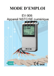
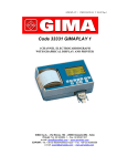
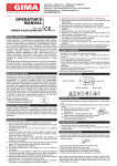
PROFESSIONAL MEDICAL PRODUCTS
Gima S.p.A. - Via Marconi, 1 - 20060 Gessate (MI) Italy
Italia: tel. 199 400 401 - fax 199 400 403
Export: tel. +39 02 953854209/221/225 fax +39 08 95380056
[email protected] - [email protected]
www.gimaitaly.com
INCONTINENCE TENS
User Manual
ATTENTION: The operators must carefully read and completely understand
the present manual before using the product.
M-28341-Rev.0.06.12
z
0434
Fabbricante/Manufacturer:
Everyway Medical Instruments Co., Ltd.
3Fl & 8Fl, No. 5, Lane 155, Sec. 3, Bei-Sheng Rd.,
Shenkeng Dist., New Taipei City, 222, Taiwan.
Rehab Europa S.L., Sant Gervasi De Cassoles, 96 3° 4a
08022 Barcelona, Spain.
1
INDEX
Chapter
1.
2.
3.
4.
5.
6.
7.
8.
9.
10.
11.
12.
13.
14.
15.
16.
17.
18.
19.
Contents.....................................................................pag.
Introduction.....................................................................2
Contraindications and Precautions.................................4
General Description.........................................................5
Construction....................................................................5
Technical Specifications..................................................6
Replaceable Parts...........................................................7
Accessories and label.....................................................7
Graphic Symbols.............................................................8
Attachment of Probe.......................................................8
Maintenance & Cleaning.................................................9
Adjusting Controls...........................................................9
Instructions for Use.......................................................11
Check & Replace Batteries...........................................13
Maintenance, Transportation and Storage....................13
Safety Control...............................................................14
Malfunction....................................................................14
Conformity to Safety Standards....................................14
Warranty....................................................................... 15
Manufacturer.................................................................15
Representative in the EU...............................................15
Option of Electrodes.....................................................16
2
Chapter 1:
INTRODUCTION
Bladder Control for Women
Urinary incontinence is an inability to hold your urine and/or faeces
until you get to a toilet. It is often temporary, and it always results
from an underlying medical condition.
Women experience incontinence twice as often as men.
Pregnancy, childbirth, menopause, and the structure of the female
urinary tract account for this difference. But both women and men
can become incontinent from neurological injury, birth defects, strokes,
multiple sclerosis, and physical problems associated with ageing.
Older women, more often than younger women, experience
incontinence. But incontinence is not inevitable with age. Incontinence
is treatable and often curable at all ages.
Incontinence in women usually occurs because of problems with
muscles that help to hold or release urine. The body stores urine
(water and waste products removed by the kidneys) in the bladder,
a balloon-like organ. The bladder connects to the urethra, the tube
through which urine leaves the body.
During urination, muscles in the wall of the bladder contract, forcing
urine out of the bladder and into the urethra. At the same time,
sphincter muscles surrounding the urethra relax, letting urine pass
out of the body. Incontinence will occur if your bladder surrounding
the urethra suddenly relax.
muscolar bladder wall
ureters
sphincter muscles
bladder
urethra
The Types of Incontinence
There are different types of Urinary Incontinence. The most common
types are Stress, Urge and Mixed incontinence.
3
Stress incontinence
Leakage of small amounts of urine when you sneeze, strain, cough,
exercise or make sudden movements. It is particularly common in
women and occurs when the bladder neck and the other mechanisms
that act to hold urine in the bladder are not working properly.
(see Figure 2)
uterus
bladder
pelvic floor musCLe
vagina
urethra
Urge Incontinence
An overactive bladder cause leakage of large amounts of urine
at unexpected times, including sleep. You may experience a strong
sudden urge to go to the toilet so that you are not able to hold on,
or have to go so frequently that it upsets your life.
Mixed Incontinence
A combination of both Stress and Urge incontinence.
Electrical Stimulation
Brief doses of electrical stimulation can strengthen muscles
in the lower pelvis in a way similar to exercising the muscles.
Electrodes are temporarily placed in the vagina or rectum to stimulate
nearby muscles. This will stabilize overactive muscles and stimulate
contraction of urethral muscles. Electrical stimulation can be used
to reduce both stress incontinence and urge incontinence.
The Stress Incontinence programme is based on strengthening
the muscles of the pelvic floor. Once muscular strength has been
improved, these muscles are better able to resist urinary leakage
caused by external pressure being applied to the bladder.
A lower-frequency current has a beneficial effect in reducing
the involuntary contractions in Urge incontinence. It works by slowing
down the rate of false signals sent to the brain. A lower frequency
is also used as a part of the Stress programme as it improves muscle
quality: blood flow and resistance to fatigue are also increased.
4
Chapter 2:
CONTRAINDICATIONS AND PRECAUTIONS
Incontinence can have many causes. The incontinence stimulator
should never be used unless the cause and source of incontinence
have been diagnosed by a medical practitioner.
Precautions
1.Read instruction manual before use of the incontinence stimulator.
2.We emphasize that patient with an implanted electronic device
(for example, a pacemaker or any implanted electronic devices)
should not undergo incontinence stimulation treatment without
consulting doctor.
3.If incontinence therapy becomes ineffective or unpleasant, stimulation
should be discontinued until its use is re-evaluated by the physician
or therapist.
4.Do not use an incontinence stimulator while operating machinery
or vehicles.
5.Turn the device off before applying or removing probe.
6.The EV-807E Incontinence stimulator device has no AP/APG protection.
Do not use it in the presence of explosive atmosphere and flammable
mixture.
7.Only use with Everyway probes.
8.Do not touch the metal electrodes of this probe after turning
the device on except for normal operation according to Chapter 12.
9.This device is in compliance with the requirements of IEC/EN 60601-1-2.
However, there is no guarantee that electromagnetic interference will not
occur in a particular way of use. Should it occur the user is encouraged
to switch off the equipment and try to minimize the interference
by increasing the separation between this device and the device which
is located as the probable source or recipient of it. Please refer
below lable:
Rated maximum
power of
transmitter (W)
0.01
0.1
1
10
100
150 Khz
to 80 MHz
80 MHz
to 800 MHz
800 MHz
to 2.5 GHz
0.1167
0.369
1.167
3.69
11.67
0.1167
0.369
1.167
3.69
11.67
0.2334
0.7378
2.334
7.378
23.34
Separation Distance in m
Interference may occur in the vicinity of
equipment marked with the following symbol:
5
Warnings
1.The incontinence stimulator should not be used during pregnancy.
2.The device should be used only under the continued supervision
of a physician.
3.The user must keep the device out of the reach of children.
4.Keep the control unit dry and away from source of heat.
Contraindications
1.Do not use incontinence stimulator if you suffer from any muscle disorder.
2.Do not use incontinence stimulator if a bladder or vaginal infection
is present.
3.Do not use incontinence stimulator if you have been diagnosed
or treated for cervical cancer.
4.Do not use incontinence stimulator if you have, or have had, epilepsy
Chapter 3:
GENERAL DESCRIPTION
The EV-807E incontinence stimulator is a battery operated pulse
generator that sends electrical impulses through probe electrodes
tothe pelvic floor muscle. The device has one controllable output
channel. A probe electrode can be connected to the output channel.
The device has 5 preset programme. The type of programme
and intensity of output is controlled by press buttons.
Chapter 4:
CONSTRUCTION
BAtteries cases
OUTPUT AMPLITUDE
programme
wave form
programme
selection control
power/on amplitude
increase control
power/oFF amplitude
DEcrease control
lead connector
6
Chapter 5:
TECHNICAL SPECIFICATIONS
MECHANISM
01 Channel TECHICAL DESCRIPTION
Single channel
02 Pulse Amplitude Adjustable, 0-80mA, Max output 80mA (peak to peak) into 500ohm load.
03 Output Voltage
Adjustable, 0-40V, Max output 40V (peak to peak) into 500ohm load.
04 Wave Form
Asymmetrical Rectangular Biphasic Pulse.
05 Power Supply
Two LITHIUM CR2032 Batteries
06 Size
77.6mm (L) x 47.8mm (W) x 17.2mm (H)
07 Weight
49.5 grams (2 batteries included)
08 Pulse Rate
Pre-setting, 1~100 Hz
09 Pulse Width
Pre-setting, 150 μs, 200 μs or 250 μs
10 Programme A, B, C, D, E, five pre-set programme of options.
11 Programme
The programme details of A, B, C, E are as follows. Parameters are
A, B, C, E
preset at fixed values. The 2 seconds ramp time including 1 second
ramp up, and 1 second ramp down. Each programme will be repeated in
a cycle pattern constantly.
Programme
Rate
Width Contraction Relaxation Ramp
Cycle
(Hz) (μs)
(Sec.) (Sec.)
(Sec.) (Sec.)
A
35 250 4
8
2
14
B
40 200 6
15 2
23
C
10
250 5
3
2
10
D
(See Column 12)
E
20 250 5
5
2
12
12 Programme D Programme D is composed with 12 sections in varied pulse rate. Each section
contains 30 contractions. The 2 seconds ramp time including 1 second ramp up,
and 1 second ramp down. The complete programme lasts 60 minutes with 360
contractions. Then repeated in a cycle pattern constantly. The details of the
programme are as given below.
Section
Rate
Width Contraction Relaxation Ramp
Cycle
(Hz)
(μs)
(Sec.)
(Sec.)
(Sec.)
(Sec.)
1
7
150
4
4
2
10
2
8
150
4
4
2
10
3
9
150
4
4
2
10
4
10
150
4
4
2
10
5
11
150
4
4
2
10
6
12
150
4
4
2
10
7
13
150
4
4
2
10
8
14
150
4
4
2
10
9
15
150
4
4
2
10
10
16
150
4
4
2
10
11
12
150
4
4
2
10
12
7
150
4
4
2
10
13 Operating
Condition
14 Remark
Temperature: 0°~40°C
Relative Humidity: 30%~75%
Atmosphere Pressure: 700Hpa~1060Hpa
There may be up to a +/-5% tolerance of all parameters and +/-20% tolerance
of amplitude & voltage.
7
Chapter 6:
REPLAECEABLE PARTS
The replaceable accessories are as given below.
NO. PARTS
01Vaginal Probe Electrode
02 Anal Probe Electrode
03 Surface Electrodes
04Lithium CR2032 Battery
05 Battery Cover
06Lead Connector
07 Main PCB
Please do not try to replace other parts of unit.
Chapter 7:
ACCESSORIES & LABEL
Accessories
Ref. No.
Description Q’ty
PR-02AVaginal Probe KB-24Lead wire GC-04Lithium CR2032 Battery Instruction Manual Carrying Pouch Rope 1
1
4
1
1
1
*See page 16 for more information about the option of probe electrodes
and surface electrodes.
Label
The label attached to the back of device contains important information
about this device: model, serial number(started with manufacturing
year and week of the device), supply voltage, the name of manufacturer,
CE number and classification. Please do not remove.
8
z
Chapter 8:
GRAPHIC SYMBOLS
1.Note Operating Instructions
2.
Degree of Electrical Protection BF
3.
Do not insert the plug into AC power supply socket.
4.
Direct Current (DC power source)
5.
Increase Intensity/Power On
6.
Decrease
Intensity/Power Off
z
7.
Consult Instructions for use
8.
Manufacturer
9.
Serial Number
Chapter 9:
ATTACHMENT OF PROBE TO THE UNIT
The lead provided with
the system inserts into
the jack socket located
on side of the device.
Holding the insulated
portion of the connector,
push the plug end of the lead
into the jack socket.
9
Chapter 10:
MAINTENANCE & CLEANING OF PROBE ELECTRODE
The internal probe electrode is for a single user only. It must be cleaned
with cold soapy water or a pad soaked in surgical spirit and then rinsed
in clean running water before and after each treatment. Dry it with a paper
towel after cleaned. The wire of probe can be cleaned by wiping with
a damp cloth.
Chapter 11:
ADJUSTING THE CONTROLS
Power On / Amplitude Increase Control
Power can be turned on when
this button is pressed for 3 seconds.
Press it again and amplitude
will be increasing lin early from 0 mA
to the desired level.
From 0 to 10mA, amplitude is increased
by 2mA each step, and from 10
to 80mA by 1mA each
step. The value is visible on the LCD.
When power is turned on, there is
60 seconds for you to adjust amplitude
after a programme is selected.
When the electrical output is started,
the LCD will show the wave form
of each pulse on the right side of LCD.
When the programme is in relaxation,
the amplitude cannot be adjusted.
a. ON
10
Power Off / Amplitude Decrease Control
Amplitude can be decreased
by pressing this button.
From 80 to 10mA, it will be decreased
by 1mA each step. From 10
to 0mA, it will be decreased
by 2mA each step.
Press the button continuously,
the amplitude will be decreased
linearly until the level desired is reached.
When amplitude is “0 mA”, power
can be turned off by pressing
this button for 3 seconds.
When amplitude is at “0 mA”,
the device will be shut off automatically
after one minute if it is not used.
c. P: Programme Selection/Urgent
Stop Control
Programme can be changed
by pressing this button when power
is turned on and the amplitude is “0mA”.
When amplitude is higher than1mA,
output will be terminated immediately
and the amplitude return to “0mA”
when this button is pressed.
When amplitude is returned to “0mA”, wait
6 seconds before re-adjusting
the unit.
b. OFF
c. P
11
Chapter 12:
INSTRUCTIONS FOR USE
The internal probe electrode is for a single user only. It must be cleaned
1.Use the toilet before beginning the treatment, if necessary
2.Clean the probe as per the instructions.
3.Make sure the stimulator is turned off before use.
4.Connect the cable of probe to the device as per the instructions.
5.Apply a thin coating of lubricating gel on the vagina opening or apply
a small amount of gel on the tip of the probe.
6. Insert the probe into the vagina, (make sure the metal contacts facing
sideways) until the flange at the base of the probe is just on the outside
and is vertical.
*Lay down or sit in a comfortable position with your knees up and your back supported by a cushion or pillow for your comfort.
7.Press the “On” button for 3 seconds and the power will be turned on.
8.Press “P” button to select a programme desired. There are 5 programs
available. The details of them are described in specifications.
9.Press the “On” button to increase amplitude
10. Press the “off” button to decrease amplitude. Once a programme
is selected, you have 60 seconds to adjust the amplitude
to a comfortable level by pressing On and Off buttons. After the
programme is started, it will be repeated in a cycle pattern as per
described in specifications.
12
11. After use, press the “P” button to stop output. Then press the “off” button for 3 seconds(When “0mA”), the power will be turned off.
12. Disconnect the lead from the control unit.
13. Remove the probe from the vagina by holding the flange.
14. Clean the probe as per the instructions.
Optional Anal Probe
The EV-807E Incontinence stimulator can also be used with an anal
probe. Place probe as shown below, and proceed as for incontinence
stimulation.
Optional Surface Electrodes
The EV-807E Incontinence stimulator can also be used with surface
electrodes.
Place the electrodes as shown below, and proceed as for continence
stimulation.
13
Chapter 13:
CHECK & REPLACE BATTERIES
Over time, in order to ensure the functional safety of the stimulator,
changing the battery is necessary.
1.Make sure that power is turned off and probe or electrodes are removed
from body.
2.Slide the battery compartment cover and open.
3.Remove the battery from the compartment.
4.Insert the battery CR2032 into the compartment. Please make sure
that the + sign is facing upwards. Remove flat batteries at once as
corrosion may damage the unit.
5.Replace the battery compartment cover and press to close.
6.The LCD will count down for 6 seconds from “666” to “111” before
its standard menu is revealed.
* The new lithium battery must be packed separately and store
in cool dry area.
Do not collide both batteries. Do not dispose of batteries on a fire
or incinerator.
Chapter 14:
MAINTENANCE, TRANSPORTATION
AND STORAGE OF DEVICE
1.Non-flammable cleaning solution is suitable for cleaning the device.
Note: Do not smoke or work with open lights (for example, candles, etc.)
when working with flammable liquids.
2.Stains and spots can be removed with a cleaning agent.
3.Do not submerge the device in liquids or expose it to large amounts
of water.
4.Return the device to the pouch to ensure that the unit is well protected before transportation.
5.If the device is not to be used for a long period of time, remove
the batteries from the battery compartment (acid may leak from used
batteries and damage the device). Pack batteries separately.
Put the device and accessories in pouch and keep it in cool dry place.
6.The packed stimulator device should be stored and transported under
the temperature range of -20°C ~ + 60°C, relative humidity 20%~ 95%, atmosphere pressure 500 hPa ~ 1060 hPa.
14
Chapter 15:
SAFETY-TECHNICAL CONTROLS
For safety reasons, check your incontinence stimulator each week
based on the following checklist.
1.Check the device for external damage.
- Deformation of the housing.
- Damaged or defective output sockets.
2.Check the device for defective operating elements.
- Legibility of inscriptions and labels.
- Make sure the inscriptions and labels are not distorted.
3.Check the usability of accessories.
- Probe undamaged.
Please consult your distributor if there are any problems with device
and accessories.
Chapter 16:
MALFUNCTIONS
Should any malfunctions occur while using the EV-807E Incontinence
stimulator, check
- Whether the cable of probe is correctly connected to the device.
The cables should be inserted completely into the sockets.
- Whether the batteries are well-inserted.
- Whether the LCD reveals the menu. If necessary, insert 2 new batteries.
- For possible damage to the cable probe. Change the probe if any
damage is detected.
* If there is any other problem, please return the device to your distributor.
Do not try to repair a defective device.
Chapter 17:
CONFORMITY TO SAFETY STANDARDS
The EV-807E Incontinence stimulator devices are in compliance with
the EN 60601-1-2:2001 and EN 60601-1:1990+A1:1993+A2:
1995+A13:1996 safety standards.
15
Chapter 18:
WARRANTY
All EV-807E Incontinence stimulator devices carry a warranty of one year from
the date of delivery. The warranty applies to the stimulator only and covers
both parts and labor relating thereto.
The warranty does not apply to damage resulting from failure to follow
the operating instructions, accidents, abuse, alteration or disassembly
by unauthorized personnel.
Manufacturer
Everyway Medical Instruments Co., Ltd.
3Fl., No.5, Lane 155, Sec. 3, Bei-Sheng Rd.,
Shen Keng Hsiang, Taipei Hsien 222, Taiwan.
Representative in the EU
Physio-Med Services
7-23 Glossop Brook Business Park,
Surrey Street, Glossop,
Derbyshire, SK13 7AJ, England.
Information for distributor
Please contact the above mentioned manufacturer for technical support
and documentation when necessary.
Copyright © 2009 by Everyway Medical Instruments Co., Ltd.
Edition: V1.2
Printed in July, 2011
16
Chapter 19:
OPTION OF ELECTRODES
This EV-807E is supplied with one standard type of probe electrode.
If you to need to to purchase a new probe electrode or adhesive electrodes,
please contact the manufacturer, EU representative (See page 17)
or the local dealer for more information. The option of electrodes suitable
for the unit are as follows.
A. Probe Electrodes with Female Plug Connection
Model #
Type
Diameter
Model # Type
Diameter
PR-02Vaginal
28mm
PR-06
Rectal
14mm
PR-03Vaginal
25mm
PR-13
Rectal
19.6mm
PR-04Vaginal
20mm
B. Probe Electrodes with 2 pig tail Connection
Model #
Type
Diameter
Model#
Type
Diameter
PR-02A Vaginal 28mm PR-06A Rectal 14mm
PR-03A Vaginal 25mm PR-13A Rectal 19.6mm
PR-04A Vaginal 20mm
PR-16A Vaginal 33mm
C. Adhesive Electrodes
Model # Shape Size
KF100 40X53mm
KF200 65X70mm
17
Disposal: The product must not be disposed of along with other
domestic waste. The users must dispose of this equipment by
bringing it to a specific recycling point for electric and electronic
equipment. For further information on recycling points contact
the local authorities, the local recycling center or the shop where
the product was purchased. If the equipment is not disposed
of correctly, fines or penalties may be applied in accordance
with the national legislation and regulations.
GIMA WARRANTY CONDITIONS
Congratulations for purchasing a GIMA product.This product meets high
qualitative standards both as regards the material and the production.
The warranty is valid for 12 months from the date of supply of GIMA.
During the period of validity of the warranty, GIMA will repair and/or replace
free of charge all the defected parts due to production reasons.
Labor costs and personnel traveling expenses and packaging not included.
All components subject to wear are not included in the warranty.
The repair or replacement performed during the warranty period shall
not extend the warranty. The warranty is void in the following cases:
repairs performed by unauthorized personnel or with non-original spare
parts, defects caused by negligence or incorrect use. GIMA cannot be held
responsible for malfunctioning on electronic devicesor software due to
outside agents such as: voltage changes, electro-magnetic elds, radio
interferences, etc. The warranty is void if the above regulations are not
observed and if the serial code (if available) has been removed, cancelled
or changed.
The defected products must be returned only to the dealer the product was
purchased from. Products sent to GIMA will be rejected.
This manual must be read and fully understood by
all relevant persons prior to use of the unit.