1
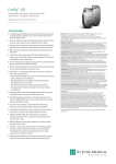
Current™ DR RF
with InvisiLink™ Wireless Telemetry
MODELS 2207-30 and 2207-36
Implantable Cardioverter Defibrillators (ICDs)
SPECIFICATIONS
• InvisiLink ™ wireless telemetry frees the clinical team during implant, and streamlines
follow-up. InvisiLink RF telemetry uses a dedicated range of frequencies designated
for medical devices called the MICS (Medical Implant Communications Service)
frequency band, which helps reduce the interference seen on frequencies used by
common household electronics.
• Designed to reduce unnecessary right ventricular pacing, the VIP algorithm allows
intrinsic conduction when possible and provides optimized ventricular support when
needed.
• Automatic Daily High Voltage Lead Test is designed to ensure patient safety.
• Multiple hardware and software system safeguards for added security and patient
comfort.
• The capability to program multiple ATP schemes per zone has the potential to
increase the success of ATP prior to requiring a shock.
®
• Our exclusive DeFT Response technology tools provide more clinically
proven, non-invasive options for managing high DFTs.
– Programmable pulse widths allow the user to tailor the shock to the individual
patient, making shocks more efficacious.1
– SVC shocking electrode can be quickly and non-invasively activated or
deactivated with the press of a button.
– 36 J delivered energy (model 2207-36) provides unsurpassed energy for defibrillation.
– Four programmable tilt options are available because no one tilt is optimal for
every patient.2
– Together, these features may help to prevent additional surgeries.
™
1
2
3
4
5
6
Mouchawar G, Kroll M, Val-Mejias JE et al. ICD waveform optimization: a randomized prospective, pair-sampled multicenter study.
PACE 2000; 23 (Part II):1992-1995.
Sweeney MO, Natale A, Volosin KJ, et al. Prospective randomized comparison of 50%/50% versus 65%/65% tilt biphasic waveform
on defibrillation in humans. PACE 2001; 24:60-65.
Baker, et al. “Acute Evaluation of Programmer-Guided AV/PV and VV Delay Optimization Comparing an IEGM Method and
Echocardiogram for Cardiac Resynchronization Therapy in Heart Failure Patients and Dual-Chamber ICD Implants” Journal of
Cardiovascular Electrophysiology, Vol. 18 No. 2, Feb. 2007.
Sperzel J, Meine M et al. A new automatic update function of the morphology template used for SVT/VT discrimination in an ICD.
Europace Supplements; Vol. 3, July 2002;A 131, #1515.
Summary of Safety and Effectiveness, P88086/S83 and P830015/S76; St. Jude Medical.
Sharma AD, O'Neill PG, Fain E, et al. Shock on T versus DC for induction of ventricular fibrillation: a randomized prospective
comparison. 21st Annual Scientific Session North American Society of Pacing and Electrophysiology (NASPE). Poster presentation
published in meeting proceedings. Washington D.C., U.S.A. May 2000.
• The SenseAbility ™ feature, with Decay Delay and Threshold Start, provides the
flexibility to fine-tune sensing to individual patient needs and help eliminate oversensing
of T waves, fractionated QRS complexes, and other extraneous signals.
• QuickOpt ™ timing provides quick and effective optimization for more patients at
the push of a button.3
– IEGM-based AV optimization allows optimized timing without need for echoguided optimization.
• The exclusive Morphology Discrimination plus AV Rate Branch SVT discrimination
feature helps reduce the risk of inappropriate ICD shocks and is intended to promote
fast, accurate diagnosis and delivery of therapy. Clinical data states that this
combination resulted in a sensitivity of 100% with a specificity of 85%.4
• Exclusive AF Suppression ™ algorithm is clinically proven to suppress episodes of
paroxysmal and persistent AF.
– Studies show a 25% decrease in symptomatic AF burden.5
• Our exclusive DC Fibber ™ induction has a documented 95.5% success rate for
inducing fibrillation on the first induction as compared with a 72.7% success
rate for Shock-on-T.6
• Exercise trend diagnostic provides insight into the patient’s disease state
progression and exercise activity.
• There are up to 45 minutes of continuous, fully annotated stored electrograms,
including up to 60 seconds of pre-trigger information per electrogram.
• Preferential EGM storage capability allows you to prioritize the way episodes are
stored.
• Exclusive vibratory Patient Notifier allows even patients with hearing problems to
be alerted to a low battery, lead-related complications and more.
Indications and Usage
The Current™ DR RF ICD is intended to provide ventricular antitachycardia pacing and ventricular defibrillation for automated treatment
of life-threatening ventricular arrhythmias. AF suppression pacing is indicated for suppression of paroxysmal or persistent atrial fibrilltion in
patients with the above ICD indication and sinus node dysfunction.
Contraindications
Contraindications for use of the pulse generator system include ventricular tachyarrhythmias resulting from transient or correctable
factors such as drug toxicity, electrolyte imbalance, or acute myocardial infarction.
Warnings and Precautions
Resuscitation Availability. Do not perform device testing unless an external defibrillator and medical personnel skilled in cardiopulmonary
resuscitation (CPR) are readily available.
Lead system. Do not use another manufacturer’s lead system without demonstrated compatibility as undersensing cardiac activity and
failure to deliver necessary therapy may result.
Avoiding shock during handling. Disable tachyarrhythmia therapy (Enable/Disable Tachy Therapy) or program tachyarrhythmia therapies
Off during surgical implant and explant or post-mortem procedures as well as when disconnecting leads as the device can deliver a
serious shock if you touch the defibrillation terminals while the device is charged.
Additional pacemaker implanted. These devices provide bradycardia pacing. If another pacemaker is used, it should have a bipolar
pacing reset mode and be programmed for bipolar pacing to minimize the possibility of the output pulses being detected by the device.
Modifying the device. This device has been tested for compliance to FCC regulations. Changes or modifications of any kind not
expressly approved by St. Jude Medical Inc. could void the user’s authority to operate this device.
Suboptimal radio frequency (RF) communication. The Merlin PCS indicates the quality of the RF communication by the telemetry
strength indicator LEDs on both the Merlin PCS and the Merlin Antenna. Please see the User’s Manual for a list of potential causes to
suboptimal radio communication.
Potential Adverse Events
Possible adverse events (in alphabetical order) associated with the system, include, but are not limited to the following: acceleration of
arrhythmias (caused by device), air embolism, allergic reaction, bleeding, cardiac tamponade, chronic nerve damage, death, erosion,
exacerbation of heart failure, excessive fibrotic tissue growth, extracardiac stimulation (phrenic nerve, diaphragm, chest wall), extrusion,
fluid accumulation, formation of hematomas or cysts, inappropriate shocks, infection, keloid formation, lead abrasion and discontinuity,
lead migration/dislodgment, myocardial damage, pneumothorax, shunting current or insulating myocardium during defibrillation with internal,
or external paddles, Potential mortality due to inability to defibrillate or pace, thromboemboli, venous occlusion, venous or cardiac perforation.
Patients susceptible to frequent shocks despite antiarrhythmic medical management, may develop psychological intolerance to an ICD or
CRT-D system that may include the following: dependency, depression, fear of premature battery depletion, fear of shocking while conscious,
fear of losing shock capability, imagined shocking (phantom shock).
Refer to the User’s Manual for detailed indications, contraindications, warnings, precautions and potential adverse events.
Current DR RF Models 2207-30 and 2207-36
Implantable Cardioverter Defibrillators
MODEL NUMBER
2207-30
2207-36
RF and Inductive
30 J
38
74
76 x 50 x 13
DF-1
IS-1
Electrically active
titanium can
RF and Inductive
36 J
42
80
77 x 50 x 14
DF-1
IS-1
Electrically active
titanium can
PHYSICAL SPECIFICATIONS
Telemetry
Delivered Energy
Volume (cc)
Weight (g)
Size (mm)
Defibrillation Lead Connections
Sense/Pace Lead Connections
High Voltage Can
Post-Therapy Pacing (Independently programmable from Bradycardia and ATP)
Post-Shock Pacing Mode
Post-Shock Base Rate (ppm)
Post-Shock Pacing Duration (min)
Post-Shock Atrial Pacing Amplitude (V)
Post-Shock Ventricular Pacing Amplitude (V)
Post-Shock Pacing Pulse Width (ms)
Off, AAI, VVI, DDI, or DDD
30-100 in increments of 5
Off, 0.5, 1, 2.5, 5, 7.5, or 10
0.25 to 7.5
0.25 to 7.5
0.05, 0.1-1.5
Device Testing/Induction Methods
PARAMETER
SETTINGS
AF Management
AF Suppression™ Pacing
No. of Overdrive Pacing Cycles
Maximum AF Suppression Rate
Off; On
15-40 in increments of 5
80-150 ppm
Threshold Start
Decay Delay
Ventricular Sense Refractory (ms)
Detection Zones
SVT Discriminators
Reconfirmation
Automatic Sensitivity Control adjustment for atrial and ventricular
events
(Post-Sensed, Atrial) 50, 62.5, 75, 100%;
(Post-Paced, Atrial) 0.2-3.0 mV;
(Post-Sensed, Ventricular) 50, 62.5, 75, 100%;
(Post-Paced, Ventricular) Auto, 0.2-3.0 mV
(Post-Sense/Post-Pace, Atrial/Ventricular) 0-220
125, 157
VT-1, VT-2, VF
AV Rate Branch, Sudden Onset, Interval Stability, Morphology
Discrimination (MD) with Manual or Automatic Template Update
Continuous sensing during charging
Therapy Summary
Episodes Summary
Lifetime Diagnostics
AT/AF Burden Trend
Ventricular HV Lead Impedance Trend
Histograms
Antitachycardia Pacing Therapy
ATP Configurations
Burst Cycle Length
Min. Burst Cycle Length (ms)
Number of Bursts
Number of Stimuli
Add Stimuli per Burst
ATP Pulse Amplitude (V)
ATP Pulse Width (ms)
Ramp, Burst, Scan; 1 or 2 schemes per zone
Adaptive, Readaptive or Fixed
150-400 in increments of 5
1-15
2-20
On, Off
7.5
Independent from Bradycardia and Post-Therapy Pacing
1.0 or 1.5;
Independently programmable from Bradycardia and
Post-Therapy Pacing
High Voltage Therapy
Waveform
RV Polarity
Electrode Configuration
Biphasic, Monophasic
Cathode (-), Anode (+)
RV to Can, RV to SVC/Can
0.5-5.0
20-100
2-25 stimuli with up to three extrastimuli
Electrograms and Diagnostics
Stored Electrograms
Sensing/Detection
SenseAbility™ Technology
DC Fibber™ Pulse Duration (sec)
Burst Fibber Cycle Length (ms)
Noninvasive Programmed Stimulation (NIPS)
PMT Data
Real-Time Measurements (RTM)
Up to 45 minutes including up to one minute
programmable pre-trigger data per VT/VF
diagnosis/detection electrograms; triggers include
diagnosis, therapy, atrial episode, PMT termination, PC
shock delivery, noise reversion, magnet reversion, and
morphology template verification
Diagram of therapies delivered
Directory listing of up to 60 episodes with access
to more details including stored electrograms
History of bradycardia events and deviceinitiated charging
Trend data and counts
Multi-Vector Trend Data
Event Histogram, AV Interval Histogram, Mode Switch
Duration Histogram, Peak Filtered Rate Histogram,
Atrial Heart Rate Histogram, Ventricular Heart Rate
Histogram, AT/AF Burden, Exercise and Activity
Trending, V Rates during AMS
Information regarding PMT detections
Pacing lead impedances, High voltage lead
impedances, unloaded battery voltage, and signal
amplitudes
Patient Notifiers
Device at ERI
Charge Time Limit Reached
Possible HV Circuit Damage
Device Reset
Atrial Lead Impedance (out of range)
Ventricular Lead Impedance (out of range)
High Voltage Lead Impedance (out of range)
Entry into Backup VVI Mode
Vibration Duration (sec)
Number of Vibrations per Notification
Number of Notifications
Time Between Notifications (hours)
Off, On
Off, On
Off, On
On
Off, On
Off, On
Off, On
On
2, 4, 6, 8, 10, 12, 14, 16
2
1-16
10, 22
Bradycardia Pacing
Permanent Modes
Temporary Modes
Rate-Adaptive Sensor
Programmable Rate Parameters
QuickOpt™ Timing Cycle Optimization
Auto Mode Switch (AMS)
AMS Detection Rate (ppm)
AMS Switch Base Rate (ppm)
Auto PMT Detection/Termination
Rate Responsive PVARP/VREF
Ventricular Intrinsic Preference (VIP®)
Cardiac Rhythm
Management Division
15900 Valley View Court
Sylmar, CA 91342 USA
888 SJM-CRMD
818 362-6822
818 362-7182 Fax
www.sjm.com
DDD(R), DDI(R), VVI(R), AAI(R), Pacer Off
Off, DDD, DDI, VVI, AAI, AAT, DOO, VOO, AOO
On, Off, Passive
Off, Base Rate (ppm), Rest Rate (ppm), Maximum Tracking
Rate (ppm), Maximum Sensor Rate (ppm), Paced AV Delay
(ms), Sensed AV Delay (ms), Rate Responsive AV Delay,
Pulse Amplitude (Atrial, RV) (V), Pulse Width (Atrial,
RV and LV) (ms), Hysteresis Rate (ppm), Rate Hysteresis
with Search
Sensed/paced AV delay
Off, DDI(R), VVI(R)
110-300
40, 45,...135
A Pace on PMT, Off, Passive
Off, Low, Medium, High
Off, 50-200 (50-150 in increments of 25;
160-200 in increments of 10)
St. Jude Medical AB
Veddestavägen 19
SE-175 84 Järfälla
SWEDEN
+46 8 474 4000
+46 8 760 9542 Fax
Ordering No. XXXXX Printed in USA 080710
CAUTION: FEDERAL LAW (USA) RESTRICTS THIS DEVICE TO SALE, DISTRIBUTION AND USE BY OR ON THE
ORDER OF A PHYSICIAN.
Consult the User’s Manual for information on indications, contraindications, warnings and precautions.
Unless otherwise noted, ™ indicates that the name is a trademark of, or licensed to, St. Jude Medical, or one of its subsidiaries.
© 2007 St. Jude Medical Cardiac Rhythm Management Division. All rights reserved.