1
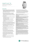
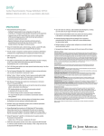
AnalyST Accel™ DR
Implantable Cardioverter Defibrillator (ICD)
with SJ4 Connector and ST Monitoring
MODEL CD2219-36q
SPECIFICATIONS
The SJ4 connector is designed to simplify implants by streamlining defibrillation
connections into a single terminal pin and minimising the number of set screws.
The SJ4 connection reduces pocket bulk, which may provide increased comfort,
particularly for patients who are thin or small in stature, and could lessen the risk
of lead-to-can abrasion, a known complication.
The ST monitoring diagnostic in the AnalyST Accel™ ICD includes:
– ST Histogram Data – graphical representation of ST deviations at
different heart rate ranges to aid in determination of ST segment shifts.
– ST Deviation Trending – total span of ST deviations over time.
– ST Episode Log – log of episodes and associated electrograms
that provide insight on significant ST segment shifts.
AutoCapture™ Pacing System offers the maximum in threshold adaptability
and patient safety with ventricular Beat-by Beat™ capture confirmation.
The AutoCapture™ Pacing System automatically delivers a 5,0 V backup
safety pulse when noncapture is detected, and it may be programmed to
either a bipolar or unipolar configuration.
ACap™ Confirm Pacing System periodically completes a threshold search and
automatically adjusts amplitude to address patients’ changing atrial thresholds.
Designed to reduce unnecessary right ventricular pacing, the VIP™ algorithm
allows intrinsic conduction when possible and provides optimised ventricular
support when needed.
– Studies show an 81% decrease in unnecessary RV pacing.1
DeFT Response™ technology tools provide more clinically proven, non-invasive
options for managing high DFTs.
– Programmable pulse widths allow the user to tailor the shock to the individual
patient, making shocks more efficacious.2
– SVC shocking electrode can be quickly and non-invasively activated or
deactivated with the touch of a button.
– 36 J delivered energy provides unsurpassed energy for defibrillation.
– Four programmable tilt options are available to accommodate variances
among patients.3
– Together, these features may help to prevent additional surgeries.
Exclusive SenseAbility™ feature, with Decay Delay and Threshold Start, provides
the flexibility to fine-tune sensing to individual patient needs and help eliminate
oversensing of T waves, fractionated QRS complexes, and other extraneous signals.
QuickOpt™ timing cycle optimisation provides quick and effective optimisation for
more patients at the touch of a button.4
– IEGM-based AV optimisation allows optimised timing without need for
echo-guided optimisation.
Exclusive Morphology Discrimination plus AV Rate Branch SVT discrimination
feature helps reduce the risk of inappropriate ICD shocks and is intended to
promote fast, accurate diagnosis and delivery of therapy. Clinical data states
that this combination resulted in a sensitivity of 100% with a specificity of 85%.5
Exclusive AF Suppression™ algorithm is clinically proven to suppress episodes
of paroxysmal and persistent AF.
– Studies show a 25% decrease in symptomatic AF burden.6
AT/AF Alerts notify patients and their clinics when a programmed AT/AF threshold
or continuous episode duration has been exceeded, or when a high ventricular rate
accompanies the AT/AF episode.
Exclusive DC Fibber™ induction has a documented 95,5% success rate for inducing fibrillation on the first induction as compared with a 72,7% success rate
for Shock-on-T.7
Exercise Trend Diagnostic provides insight into the patient’s disease state
progression and exercise activity.
Up to 45 minutes of continuous, fully annotated stored electrograms,
including up to 60 seconds of pre-trigger information per electrogram.
—
Preferential EGM storage capability allows prioritisation of episode storage.
Vibratory Patient Notifier allows even patients with hearing problems to be alerted
to a low battery, lead-related complications and more.
Automatic Daily High-Voltage (HV) Lead Integrity Test is designed to
automatically test the HV lead on a daily basis to ensure therapy delivery
for optimal patient safety.
Multiple hardware and software system safeguards provide added security
and patient comfort.
The capability to program multiple ATP schemes per zone has the potential
to increase the success of ATP prior to requiring a shock.
InvisiLink™ Wireless Telemetry, in conjunction with the Merlin@home™ transmitter
and Merlin.net™ Patient Care Network (PCN), allows for seamless remote monitoring
and follow-up. InvisiLink™ RF telemetry uses a dedicated range of frequencies
designated for medical devices called the MICS (Medical Implant Communications
Service) frequency band, which helps reduce the interference seen on frequencies
used by common household electronics.
Indications: The devices are intended to provide ventricular antitachycardia pacing and ventricular defibrillation
for automated treatment of life-threatening ventricular arrhythmias.
Contraindications: Contraindications for use of the pulse generator system include ventricular
tachyarrhythmias resulting from transient or correctable factors such as drug toxicity, electrolyte imbalance, or
acute myocardial infarction.
Warnings and Precautions:
Implantation Procedure. The physician should be familiar with all components of the system and the material in
this manual before beginning the procedure. Ensure that a separate standby external defibrillator is immediately
available. Implant the pulse generator no deeper than 5 cm to ensure reliable data transmission. For patient
comfort, do not implant the pulse generator within 1,25 cm of bone unless you cannot avoid it.
Device Replacement. Replace the pulse generator within three months of reaching the 2,45 V indication.
Replace the pulse generator immediately upon reaching 2,45 V if there is frequent high-voltage charging and/or
one or more of the pacing outputs are programmed above 2,5 V.
Battery Incineration. Do not incinerate pulse generators as they contain sealed chemical power cells and
capacitors that may explode. Return explanted devices to St. Jude Medical.
High-Voltage Can. Ensure that tachyarrhythmia therapy is programmed Off before handling the pulse generator
to avoid any risk of accidental shock. Do not program tachyarrhythmia therapies On until the pulse generator is
inserted in the pocket. For effective defibrillation, perform all defibrillation testing with the can in the pocket.
Magnetic Resonance Imaging (MRI). Avoid MRI devices because of the magnitude of the magnetic fields and
the strength of the radiofrequency (RF) fields they produce.
Device Storage. Store the pulse generator at temperatures between 10° and 45°C. Do not subject it to
temperatures below -20° or over 60°C. After cold storage, allow the device to reach room temperature before
charging the capacitors, programming, or implanting the device because cold temperature may affect initial
device function.
Device Communication. Communication with the device can be affected by electrical interference and strong
magnetic fields. If this is a problem, turn off nearby electrical equipment or move it away from the patient and
the programmer. If the problem persists, contact St. Jude Medical.
Lead Impedance. Do not implant the pulse generator if the acute defibrillation lead impedance is less than 20
ohms or the lead impedance of chronic leads is less than 15 ohms. Damage to the device may result if highvoltage therapy is delivered into an impedance less than 15 ohms.
Suboptimal RF Communication. The Merlin™ PCS indicates the quality of the RF communication by the telemetry
strength indicator LEDs on both the programmer and the Merlin Antenna.
Disconnecting Leads. Connecting or disconnecting sense/pace leads can produce electrical artifacts that
can be sensed by the pulse generator. To prevent detection of artifacts, reprogram the pulse generator to
tachyarrhythmia therapy Off: Before disconnecting the leads from a pulse generator in the operating room;
Before a post-mortem examination; Whenever there are no leads connected to it; When sense/pace leads are
connected but are not implanted in a patient. If a programmer is not available, use a magnet to prevent delivery
of tachyarrhythmia therapy in response to detected disconnection artifacts. Place the magnet over the pulse
generator before disconnecting the leads. Do not remove it until the leads are reconnected.
External Equipment for Arrhythmia Induction. If external equipment is used for arrhythmia induction through
the pulse generator header and leads, apply rectified AC current through the high-voltage ports, not the sense/
pace ports, to avoid damaging the sense/pace function: disconnect the external equipment from the pulse
generator before any therapy is delivered; otherwise, damage to the device is likely to occur. Place a magnet over
the device until the external equipment can be disconnected.
Adverse Events:
Implantation of the pulse generator system, like that of any other device, involves risks, some possibly
life-threatening. These include but are not limited to the following: acute hemorrhage/bleeding, air emboli,
arrhythmia acceleration, cardiac or venous perforation, cardiogenic shock, cyst formation, erosion, exacerbation
of heart failure, extrusion, fibrotic tissue growth, fluid accumulation, hematoma formation, histotoxic reactions,
infection, keloid formation, myocardial irritability, nerve damage, pneumothorax, thromboemboli, venous
occlusion. Other possible adverse effects include mortality due to: component failure, device-programmer
communication failure, lead abrasion, lead dislodgment or poor lead placement, lead fracture, inability to
defibrillate, inhibited therapy for a ventricular tachycardia, interruption of function due to electrical or magnetic
interference, shunting of energy from defibrillation paddles, system failure due to ionising radiation. Other
possible adverse effects include mortality due to inappropriate delivery of therapy caused by: multiple counting
of cardiac events including T waves, P waves, or supplemental pacemaker stimuli. Among the psychological
effects of device implantation are imagined pulsing, dependency, fear of inappropriate pulsing, and fear of
losing pulse capability.
Refer to the User’s Manual for detailed indications, contraindications, warnings, precautions and potential
adverse events.
Post-Therapy Pacing (Independently programmable from Bradycardia and ATP )
PHYSICAL SPECIFICATIONS
Models
Telemetry
Delivered Energy
Volume (cc)
Weight (g)
Size (mm)
Defibrillation Lead Connections
Sense/Pace Lead Connections
High Voltage Can
CD2219-36Q
RF
36 J
41
80
74 x 50 x 14
SJ4
IS-1; SJ4
Electrically active titanium can
Post-Shock Pacing Mode
Post-Shock Base Rate (min-1)
Post-Shock Pacing Duration (min)
PARAMETERS
Settings
Patient Notifiers
Device Testing/Induction Methods
DC Fibber™ Pulse Duration (sec)
Burst Fibber Cycle Length (ms)
Noninvasive Programmed
Stimulation (NIPS)
AF Management
AF Suppression™ Pacing
No. of Overdrive Pacing Cycles
Maximum AF Suppression Rate
Programmable Notifiers (On, Off)
Device Parameter Reset
Entry into Backup VVI Mode
Vibration Duration (sec)
Number of Vibrations per Notification
Number of Notifications
Time Between Notifications (hours)
On; Off
15-40 in increments of 5
80-150 min-1
Sensing/Detection
SenseAbility™ Technology
Threshold Start
Decay Delay
Ventricular Sense Refractory (ms)
Detection Zones SVT Discriminators
Reconfirmation
Automatic Sensitivity Control adjustment for atrial and ventricular events
(Post-Sensed, Atrial) 50; 62,5; 75; 100%;
(Post-Paced, Atrial) 0,2-3,0 mV;
(Post-Sensed, Ventricular) 50; 62,5; 75; 100%;
(Post-Paced, Ventricular) Auto; 0,2-3,0 mV
(Post-Sense/Post-Pace, Atrial/Ventricular) 0-220
125; 157
VT-1; VT-2; VF
AV Rate Branch; Sudden Onset, Interval Stability; Morphology
Discrimination (MD) with Manual or Automatic Template Update
Continuous sensing during charging
Stored Electrograms
Therapy Summary
Episodes Summary
Lifetime Diagnostics
AT/AF Burden Trend
Ventricular HV Lead Impedance Trend
Histograms
PMT Data
Real-Time Measurements (RTM)
ST Monitoring
Ramp; Burst; Scan; 1 or 2 schemes per zone
Adaptive; Readaptive or Fixed
150-400 in increments of 5
1-15
2-20
On; Off
7,5 Independent from Bradycardia and Post-Therapy Pacing
1,0 or 1,5 Independently programmable from Bradycardia
and Post-Therapy Pacing
High-Voltage Therapy
High-Voltage Output Mode Waveform
RV Polarity
Electrode Configuration
Fixed Pulse Width; Fixed Tilt
Biphasic; Monophasic
Cathode (-), Anode (+)
RV to Can; RV to SVC/Can
Bradycardia Pacing
Permanent Modes
DDD(R); DDI(R); VVI(R); AAI(R); Pacer Off
Temporary Modes
Off; DDD; DDI; VVI; AAI; AAT; DOO; VOO; AOO
Rate-Adaptive Sensor
(Post-Sense/Post-Pace; Atrial/Ventricular) 0-220
Programmable
Rate and Delay Parameters
Off; Base Rate (min-1); Rest Rate (min-1); Maximum Tracking Rate (min-1);
Maximum Sensor Rate (min-1); Paced AV Delay (ms); Sensed AV Delay (ms);
Rate Responsive AV Delay; Pulse Amplitude (Atrial, RV) (V); Pulse Width (Atrial and RV) (ms); Hysteresis Rate (min-1); Rate Hysteresis with Search
™
QuickOpt Timing Cycle Optimisation Sensed/Paced AV delay
Auto Mode Switch (AMS)
Off; DDI(R); VVI(R)
Atrial Tachycardia
-1
Detection Rate (min )
110-300
AMS Base Rate (min-1)
40; 45;...135
Auto PMT Detection/Termination
A Pace on PMT; Off; Passive
Rate Responsive PVARP/VREF
Off; Low; Medium; High
™
Ventricular Intrinsic Preference (VIP ) Off; 50-200 (50-150 in increments of 25; 450 to 200 in increments of 10)
™
Ventricular AutoCapture
Pacing System
On; Off
ACap™ Confirm
On; Monitor; Off
Atrial Fibrillation
Cardiac Rhythm Management
Cardiac Surgery
Cardiology
Global Headquarters
One Lillehei Plaza
St. Paul, Minnesota 55117
USA
+1 651 483 2000
+1 651 490 4310 Fax
Cardiac Rhythm
Management Division
15900 Valley View Court
Sylmar, California 91342
USA
+1 818 362 6822
+1 818 364 5814 Fax
St. Jude Medical Sweden AB
Veddestavägen 19
175 84 Järfälla
Sweden
+46 8 474 40 00
+46 8 760 95 42 Fax
St. Jude Medical
Coordination Center BVBA
The Corporate Village
Da Vincilaan 11 Box F1
1935 Zaventem
Belgium
+32 2 774 68 11
+32 2 772 83 84 Fax
St. Jude Medical Brasil Ltda.
Rua Frei Caneca, 1380
7º ao 9º andares
01307-002 - São Paulo (SP)
Brazil
+55 11 5080 5400
+55 11 5080 5423 Fax
St. Jude Medical (Hong Kong) Ltd.
Unit 2701-07 27/F, COSCO Tower
Grand Millennium Plaza
183 Queen’s Road
Central, Hong Kong
+852 2996 7688
+852 2956 0622 Fax
0,5-5,0
20-100
2-25 stimuli with up to three extrastimuli
Device at ERI; Charge Time Limit Reached; Possible HV Circuit Damage;
Atrial Lead Impedance Out of Range; Ventricular Lead Impedance Out
of Range; High-Voltage Lead Impedance Out of Range; AT/AF Burden
On
On
2; 4; 6; 8; 10; 12; 14; 16
2
1-16
10; 22
Electrograms and Diagnostics
Antitachycardia Pacing Therapy
ATP Configurations
Burst Cycle Length
Min. Burst Cycle Length (ms)
Number of Bursts
Number of Stimuli
Add Stimuli per Burst
ATP Pulse Amplitude (V)
ATP Pulse Width (ms)
Off; AAI; VVI; DDI; or DDD
30-100 in increments of 5
Off; 0,5; 1; 2,5; 7,5; or 10
Up to 45 minutes including up to one minute programmable pre-trigger data per VT/VF diagnosis/detection electrograms; triggers include
diagnosis; therapy; atrial episode; PMT termination; PC shock delivery;
noise reversion; magnet reversion; and morphology template verification
Diagram of therapies delivered
Directory listing of up to 60 episodes with access to more details including
stored electrograms
History of bradycardia events and device-initiated charging
Trend data and counts
Multi-Vector Trend Data
Event Histogram; AV Interval Histogram; Mode Switch Duration Histogram;
Peak Filtered Rate Histogram; Atrial Heart Rate Histogram; Ventricular
Heart Rate Histogram; AT/AF Burden; Exercise and Activity Trending; V
Rates during AMS
Information regarding PMT detections
Pacing lead impedances; high voltage lead impedances; unloaded battery
voltage; and signal amplitudes
ST Histogram Data; ST Deviation Trend; ST Episode Log
1 Matthew T Bennett et al. The ICD alert is potentially an unreliable ICD warning feature. Canadian Cardiovascular Congress.
2 Mouchawar G, Kroll M, Val-Mejias JE et al. ICD waveform optimization: a randomized prospective,
pair-sampled multicenter study. PACE 2000; 23 (Part II):1992-1995.
3 Sweeney MO, Natale A, Volosin KJ, et al. Prospective randomized comparison of 50%/50% versus
65%/65% tilt biphasic waveform on defibrillation in humans. PACE 2001; 24:60-65.
4 Baker, et al. Acute Evaluation of Programmer-Guided AV/PV and VV Delay Optimization Comparing
an IEGM Method and Echocardiogram for Cardiac Resynchronization Therapy in Heart Failure Patients
and Dual-Chamber ICD Implants. Journal of Cardiovascular Electrophysiology, Vol. 18 No. 2, Feb. 2007.
5 Sperzel J, Meine M et al. A new automatic update function of the morphology template used for SVT/VT
discrimination in an ICD. Europace Supplements; Vol. 3, July 2002;A 131, #1515.
6 Carlson MD et al. A new pacemaker algorithm for the treatment of atrial fibrillation: results of the Atrial Dynamic
Overdrive Pacing Trial (ADOPT). JACC 2003; 42:627-633.
7 Sharma AD, O’Neill PG, Fain E, et al. Shock on T versus DC for induction of ventricular fibrillation:
a randomized prospective comparison. 21st Annual Scientific Session North American Society of Pacing
and Electrophysiology (NASPE). Poster presentation published in meeting proceedings. Washington D.C.,
U.S.A. May 2000.
Neuromodulation
St. Jude Medical Japan Co., Ltd.
3-1-30, Minami-Aoyama
Minato-ku
Tokyo 107 0062
Japan
+81 3 3423 6450
+81 3 3402 5586 Fax
sjm.com
Brief Summary: Prior to using these devices, please review the Instructions for Use for a complete listing of indications, contraindications, warnings, precautions, potential adverse events
and directions for use. Devices depicted may not be available in all countries. Check with your St. Jude Medical representative for product availability in your country. Unless otherwise noted,
™ indicates that the name is a trademark of, or licensed to, St. Jude Medical or one of its subsidiaries. ST. JUDE MEDICAL, the nine-squares symbol and MORE CONTROL. LESS RISK. are
trademarks and service marks of St. Jude Medical, Inc. and its related companies. ©2009 St. Jude Medical, Inc. All Rights Reserved.
Item No. XXXXXXXXX