1
2.3 Performance Specifications
1. Introduction
Table 2.1: Performance Specifications
The FX1N-1DA-BD analog output expansion board (hereafter called “1DA” or “expansion board”) is to be
installed in an FX1S or FX1N series PLC, to increase the analog output by 1 point.
FX1N-1DA-BD Analog Output Expansion Board
User’s Manual
JY992D96401A
This manual contains text, diagrams and explanations which will guide the reader in the correct
installation, safe use and operation of the FX1N-1DA-BD Analog Output Expansion Board and should be
read and understood before attempting to install or use the unit. Further information can be found in the
associated manuals list below.
1.1 Features of 1DA
1) Analog output of 1 point can be increased using 1DA. If a 1DA is used, internal mounting in the top of
the PLC means there is no need for a change to the installation area of the PLC.
2) Voltage output (0 ~ 10V) or current output (4 ~ 20mA) for digital to analog conversion can be set by
switching a dedicated special auxiliary relay.
Moreover, the digital value for conversion is stored in a dedicated special data register, as shown in
the table below.
However, the digital to analog conversion characteristics cannot be adjusted.
Table 1.1: Allocated Device
Device
a) Any engineer using the product associated with this manual, should be of a competent nature,
trained and qualified to the local and national standards. These engineers should be fully aware of
all aspects of safety with regards to automated equipment.
M8114
Switch of output mode
OFF: Voltage output mode (0 ~ 10V)
ON:
Current output mode (4 ~ 20mA)
D8114
Digital value for analog output
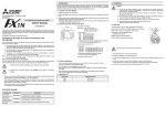
4 3 (1 .6 9 ")
a )
V +
Note: The term ‘completed equipment’ refers to a third party constructed device which contains or uses
the product associated with this manual.
I+
V I-
Note’s on the Symbols Used in this Manual
b )
At various times through out this manual certain symbols will be used to highlight points of information
which are intended to ensure the users personal safety and protect the integrity of equipment.
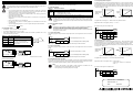
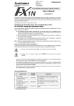
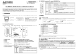
Terminal name
Content
•
c )
No connection (DO NOT use this terminal)
V+
Voltage output terminal
I+
Current output terminal
VI-
Common terminal for analog output
b) Mounting holes (2- ∅4.0 / 0.16")
c) Connector for PLC
•
All examples and diagrams shown in this manual are intended only as an aid to understanding the
text, not to guarantee operation. Mitsubishi Electric will accept no responsibility for actual use of the
product based on these illustrative examples.
•
Owing to the very great variety in possible application of this equipment, you must satisfy yourself as
to its suitability for your specific application.
Associated Manual
Manual Name
¤
Description
FX 1S Series
Programmable controllers
Hardware Manual
JY992D83901
FX1N Series
Programmable controllers
Hardware Manual
JY992D89301
Describes contents related to hardware of FX1N
Series PLC, such as specifications, wiring and
installation.
JY992D88101
Describes instructions in FX1S/FX1N/FX2N/FX2NC
series.
FX Series of
Programmable controllers
Programming Manual ΙΙ
¤ Indispensable manual
Describes contents related to hardware of FX1S
Series PLC, such as specifications, wiring and
installation.
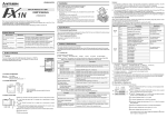
12bit binary
Resolution
2.5mV (10V /4000)
8µA {(20mA - 4mA) /2000}
Integrated
accuracy
±1% Against the full scale
(0 ~ 10V: ±0.1V)
±1% Against the full scale
(4 ~ 20mA: ±0.16mA)
D/A conversion
time
1 scan time (Analog to digital conversion is executed at the END instruction).
20mA
Analog
output
4mA
Analog
output
0
Occupied point
0 ~ 2000 are adjusted to 4 ~ 20mA
when the external load is 250Ω.
4000
Digital input
0
2000
Digital input
0 points (1DA is not subject to the standard maximum number of control points in
the host PLC, as it operates via a data register).
Note:
1) When external load resistance is 2kΩ, the overall accuracy of voltage output is adjusted
“±1%”
If external load becomes larger than 2kΩ, the output voltage will increase slightly. When
the load is 1MΩ, the output voltage becomes about 3% higher than the correct value.
2) When using current output, be sure to have an external load resistance of 500Ω or less.
If the load is greater than 500Ω, the output current will be lower than the correct value.
3. Installation
Caution:
1.3 System Configuration
•
Only one expansion board can be used on one FX1S and FX1N PLC main unit.
Do not try to install two or more expansion board. (They will not function)
•
The 1DA cannot be used together with a FX1N-EEPROM-8L or FX1N-5DM.
•
Cut off all phases of power source before installing / removing or performing wiring work
on the expansion board in order to avoid electric shock or damage of product.
•
After the installation and wiring etc. replace the PLCs top cover before power ON.
Note:
1.4 Applicable PLC
Table 1.3: Applicable Programmable Controller
PLC Type
Applicable version
FX1S series
V2.00 or later
FX1N series
V2.00 or later
2. Specifications
Manual
Number
Digital output
Input
characteristics
Table 1.2: Allocation of Terminals
1) Indicates that the identified danger WILL cause physical and property damage.
Under no circumstances will Mitsubishi Electric be liable or responsible for any consequential damage
that may arise as a result of the installation or use of this equipment.
DC 4 ~ 20mA
(External load resistance 500Ω or less)
10V
a) Terminals to connect analog module
The top face of this terminal block is higher than the top face of the
panel cover of the programmable controller by approximately 7mm
(0.28").
b )
c) All operators of the completed equipment should be trained to use that product in a safe and
coordinated manner in compliance to established safety practices.
•
Current output
DC 0 ~ 10V
(External load resistance 2k ~ 1MΩ)
Dimensions: mm (inches) Accessory: Top cover for board ×1,
M3 self-tapping screw ×3 (to fix top cover ×1, to mount board ×2)
b) Any commissioning or service engineer must be of a competent nature, trained and qualified to
the local and national standards.
2) Indicates that the identified danger could POSSIBLY cause physical and property
damage.
Voltage output
0 ~ 4000 are adjusted to 0 ~ 10V when
the external load is 2kΩ.
1.2 External Dimensions and Each Part Name
3 8 .5 (1 .5 2 ")
This manual has been written to be used by trained and competent personnel. The definition of such a
person or persons is as follows:
Range of analog
output
Description
Specifications are subject to change without notice
Guidelines for the Safety of the User and Protection of the
FX1N-1DA-BD Analog Output Expansion Board.
Specification
Item
2.1 General Specifications
Same as the programmable controller main unit. (Refer to the programmable controller main unit manual)
2.2 Power Supply Specifications
Power supplied by internal feed of the programmable controller main unit.
•
Securely install the expansion board, and fix to the PLC. Defective contact can cause
malfunction.
•
The tightening torque for fixing the board or top cover is 0.3 ~ 0.6 Nžm. Tighten securely to
avoid malfunction.
Note:
Only one expansion board can be used per main unit of FX1S and FX1N series PLC. Do not try
to install two or more expansion boards.
Moreover, the 1DA cannot be used with the FX1N-EEPROM-8L or FX1N-5DM.
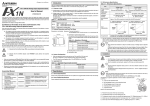
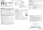
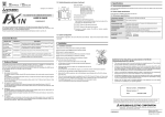
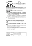
The following is a generic explanation of how to install an expansion board
to the PLC.
a )'
a )
a) Top cover for expansion board
c )
b) M3 self-tapping screw to mount expansion board
c) M3 self-tapping screw to fix top cover
b )
e )
c )
d) External port for optional equipment
e) Expansion board
Note: Do not remove this screw.
d )
N o te )
1) Remove the top cover of the main unit and keep.
2) Plug expansion board “e)” into the external port “d)”.
3) Fix expansion board to main unit using M3 self-tapping screws “c)”. (Tightening torque: 0.3 ~ 0.6N⋅m)
4) Attach top cover for expansion board “a)” removing section “a)’” to expose connector etc.
5) Secure top cover with M3 self-tapping screw “b)”. (Tightening torque: 0.3 ~ 0.6N⋅m)
2.3 Performance Specifications
1. Introduction
Table 2.1: Performance Specifications
The FX1N-1DA-BD analog output expansion board (hereafter called “1DA” or “expansion board”) is to be
installed in an FX1S or FX1N series PLC, to increase the analog output by 1 point.
FX1N-1DA-BD Analog Output Expansion Board
User’s Manual
JY992D96401A
This manual contains text, diagrams and explanations which will guide the reader in the correct
installation, safe use and operation of the FX1N-1DA-BD Analog Output Expansion Board and should be
read and understood before attempting to install or use the unit. Further information can be found in the
associated manuals list below.
1.1 Features of 1DA
1) Analog output of 1 point can be increased using 1DA. If a 1DA is used, internal mounting in the top of
the PLC means there is no need for a change to the installation area of the PLC.
2) Voltage output (0 ~ 10V) or current output (4 ~ 20mA) for digital to analog conversion can be set by
switching a dedicated special auxiliary relay.
Moreover, the digital value for conversion is stored in a dedicated special data register, as shown in
the table below.
However, the digital to analog conversion characteristics cannot be adjusted.
Table 1.1: Allocated Device
Device
a) Any engineer using the product associated with this manual, should be of a competent nature,
trained and qualified to the local and national standards. These engineers should be fully aware of
all aspects of safety with regards to automated equipment.
M8114
Switch of output mode
OFF: Voltage output mode (0 ~ 10V)
ON:
Current output mode (4 ~ 20mA)
D8114
Digital value for analog output
4 3 (1 .6 9 ")
a )
V +
Note: The term ‘completed equipment’ refers to a third party constructed device which contains or uses
the product associated with this manual.
I+
V I-
Note’s on the Symbols Used in this Manual
b )
At various times through out this manual certain symbols will be used to highlight points of information
which are intended to ensure the users personal safety and protect the integrity of equipment.
Terminal name
Content
•
c )
No connection (DO NOT use this terminal)
V+
Voltage output terminal
I+
Current output terminal
VI-
Common terminal for analog output
b) Mounting holes (2- ∅4.0 / 0.16")
c) Connector for PLC
•
All examples and diagrams shown in this manual are intended only as an aid to understanding the
text, not to guarantee operation. Mitsubishi Electric will accept no responsibility for actual use of the
product based on these illustrative examples.
•
Owing to the very great variety in possible application of this equipment, you must satisfy yourself as
to its suitability for your specific application.
Associated Manual
Manual Name
¤
Description
FX 1S Series
Programmable controllers
Hardware Manual
JY992D83901
FX1N Series
Programmable controllers
Hardware Manual
JY992D89301
Describes contents related to hardware of FX1N
Series PLC, such as specifications, wiring and
installation.
JY992D88101
Describes instructions in FX1S/FX1N/FX2N/FX2NC
series.
FX Series of
Programmable controllers
Programming Manual ΙΙ
¤ Indispensable manual
Describes contents related to hardware of FX1S
Series PLC, such as specifications, wiring and
installation.
12bit binary
Resolution
2.5mV (10V /4000)
8µA {(20mA - 4mA) /2000}
Integrated
accuracy
±1% Against the full scale
(0 ~ 10V: ±0.1V)
±1% Against the full scale
(4 ~ 20mA: ±0.16mA)
D/A conversion
time
1 scan time (Analog to digital conversion is executed at the END instruction).
20mA
Analog
output
4mA
Analog
output
0
Occupied point
0 ~ 2000 are adjusted to 4 ~ 20mA
when the external load is 250Ω.
4000
Digital input
0
2000
Digital input
0 points (1DA is not subject to the standard maximum number of control points in
the host PLC, as it operates via a data register).
Note:
1) When external load resistance is 2kΩ, the overall accuracy of voltage output is adjusted
“±1%”
If external load becomes larger than 2kΩ, the output voltage will increase slightly. When
the load is 1MΩ, the output voltage becomes about 3% higher than the correct value.
2) When using current output, be sure to have an external load resistance of 500Ω or less.
If the load is greater than 500Ω, the output current will be lower than the correct value.
3. Installation
Caution:
1.3 System Configuration
•
Only one expansion board can be used on one FX1S and FX1N PLC main unit.
Do not try to install two or more expansion board. (They will not function)
•
The 1DA cannot be used together with a FX1N-EEPROM-8L or FX1N-5DM.
•
Cut off all phases of power source before installing / removing or performing wiring work
on the expansion board in order to avoid electric shock or damage of product.
•
After the installation and wiring etc. replace the PLCs top cover before power ON.
Note:
1.4 Applicable PLC
Table 1.3: Applicable Programmable Controller
PLC Type
Applicable version
FX1S series
V2.00 or later
FX1N series
V2.00 or later
2. Specifications
Manual
Number
Digital output
Input
characteristics
Table 1.2: Allocation of Terminals
1) Indicates that the identified danger WILL cause physical and property damage.
Under no circumstances will Mitsubishi Electric be liable or responsible for any consequential damage
that may arise as a result of the installation or use of this equipment.
DC 4 ~ 20mA
(External load resistance 500Ω or less)
10V
a) Terminals to connect analog module
The top face of this terminal block is higher than the top face of the
panel cover of the programmable controller by approximately 7mm
(0.28").
b )
c) All operators of the completed equipment should be trained to use that product in a safe and
coordinated manner in compliance to established safety practices.
•
Current output
DC 0 ~ 10V
(External load resistance 2k ~ 1MΩ)
Dimensions: mm (inches) Accessory: Top cover for board ×1,
M3 self-tapping screw ×3 (to fix top cover ×1, to mount board ×2)
b) Any commissioning or service engineer must be of a competent nature, trained and qualified to
the local and national standards.
2) Indicates that the identified danger could POSSIBLY cause physical and property
damage.
Voltage output
0 ~ 4000 are adjusted to 0 ~ 10V when
the external load is 2kΩ.
1.2 External Dimensions and Each Part Name
3 8 .5 (1 .5 2 ")
This manual has been written to be used by trained and competent personnel. The definition of such a
person or persons is as follows:
Range of analog
output
Description
Specifications are subject to change without notice
Guidelines for the Safety of the User and Protection of the
FX1N-1DA-BD Analog Output Expansion Board.
Specification
Item
2.1 General Specifications
Same as the programmable controller main unit. (Refer to the programmable controller main unit manual)
2.2 Power Supply Specifications
Power supplied by internal feed of the programmable controller main unit.
•
Securely install the expansion board, and fix to the PLC. Defective contact can cause
malfunction.
•
The tightening torque for fixing the board or top cover is 0.3 ~ 0.6 Nžm. Tighten securely to
avoid malfunction.
Note:
Only one expansion board can be used per main unit of FX1S and FX1N series PLC. Do not try
to install two or more expansion boards.
Moreover, the 1DA cannot be used with the FX1N-EEPROM-8L or FX1N-5DM.
The following is a generic explanation of how to install an expansion board
to the PLC.
a )'
a )
a) Top cover for expansion board
c )
b) M3 self-tapping screw to mount expansion board
c) M3 self-tapping screw to fix top cover
b )
e )
c )
d) External port for optional equipment
e) Expansion board
Note: Do not remove this screw.
d )
N o te )
1) Remove the top cover of the main unit and keep.
2) Plug expansion board “e)” into the external port “d)”.
3) Fix expansion board to main unit using M3 self-tapping screws “c)”. (Tightening torque: 0.3 ~ 0.6N⋅m)
4) Attach top cover for expansion board “a)” removing section “a)’” to expose connector etc.
5) Secure top cover with M3 self-tapping screw “b)”. (Tightening torque: 0.3 ~ 0.6N⋅m)
4. Wiring
Caution:
Cut off all phases of power source before installing / removing or performing wiring work on
the expansion board in order to avoid electric shock or damage of product.
•
•
An analog output is converted from a digital value (D8114) using the DA conversion characteristic
specified by special auxiliary relay M8114 at each END instruction.
5.1 Allocated Device
Do not lay signal cable near to high voltage power cable or house them in the same
trunking duct. Effects of noise or surge induction may occur. Keep signal cables a safe
distance of more than 100 mm (3.94") from these power cables.
Ground the shied wire or the shield of a shielded cable. Do not, however, ground at the
same point as high voltage lines.
Device
•
Never connect cables of a non permitted size.
•
Fix cables so that any stress is not directly applied on the terminal block or the cable
connection area.
•
The terminal tightening torque is 0.5 ~ 0.6 Nžm. Tighten securely to avoid malfunction.
•
Do not use to the
•
Switch of output mode
OFF: Voltage output mode (0 ~ 10V)
ON:
Current output mode (4 ~ 20mA)
D8114
Digital value (When power supply is turned ON, D8114 will initials to “0”.)
This D/A conversion is done regardless of the RUN/STOP status of the PLC. Any time power
is supplied to the PLC when the 1DA is attached, the analog value in D8114 will be output.
The analog output value will continue to be output when the PLC status is changed from RUN
to STOP!
The maximum tightening torque is 0.5 ~ 0.6 N•m.
•
When using a different type of cable, defective contact at the terminal is possible. Use a crimp
terminal to achieve a good contact.
Table 4.1: Liner and Sectional Area
Linear
Sectional
Area (mm2)
AWG26
0.1288
:
:
:
:
AWG16
1.309
Stranded cable: Remove sheath, twist
core wires, then connect cable.
Single cable: Remove sheath, then
connect cable.
FNC 23
D DIV
D2
K5
D4
FNC 12
MOV
D4
D8114
M8114
Set in voltage output mode (0 ~ 10V).
5.3.2 Example Application Program 2
FNC 12
MOV
6mm
D0*1
D8114
D0*1 is converted digital value to analog output.
*1 If a digital value is not stored in D0, D8114 can be used directly for other instructions.
M8000
M8114
FNC 12
MOV
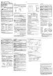
Grounding resistance of
100Ω or less (Class D)
D2*1
D8114
Set in current output mode (4 ~ 20mA).
*1 If a digital value is not stored in D2, D8114 can be used directly for other instructions.
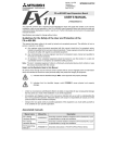
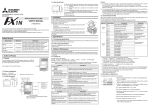
4.2.2 Current Output Mode
5.3 Example Application Program
AG
Grounding resistance of
100Ω or less (Class D)
As the 1DA does not have Offset and Gain capabilities, if values are required outside the standard
specification range, additional program commands are required to either multiply or divide the conversion
values. For an example application program, please see FX programming manual II.
Note:
•
•
In current output mode, the 1DA converts digital values from 0 ~ 2000 to the analog output of 0 ~ 20 mA.
If using a digital range of 0 ~ A in the program, the range must be converted to 0 ~ 4000 as shown in the
programming example below. Digital values for conversion to analog are stored in D8114.
The analog output does not have exact resolution of 8 µA because the digital value is converted from 0 ~
A to range of 0 ~ 2000. A > 0.
2000
Accuracy and resolution of the digital to analog conversion are different from the
specification because of the additional program commands.
The original range of the analog output is not changed.
20mA
Digital value for
analog output
(D8114)
Analog
output
4mA
0
D2*1 is converted digital value to analog output.
*1 Connect a 0.1 ~ 0.47µF at 25V DC capacitor in position”*1” when there will be a lot of noise.
FX1N-1DA-BD
M8000
The following program example sets the voltage output mode, and a digital value in D0 is converted to
analog.
The following program example sets the current output mode, and a digital value in D2 is converted to
analog.
Record
meter, etc.
M8114
D2
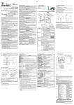
4.2.1 Voltage Output Mode
V+
I+
VI-
M8001
D0
5.2.2 Current Output Mode
AG
The value of D0 is given as a multiple of five.
K2
M8000
*1 Inverter, etc.
0
4000
Digital value for analog output (D8114)
If a digital value in the range of 0 ~ 10000 is used in D0, please see below.
FNC 22
MUL
4.2 Wiring
V+
I+
VI-
0
0
10000
Digital value used in user program (D0)
5.2.1 Voltage Output Mode
M8001
Terminal
0
Note:
Drive M8114 which specifies the digital to analog conversion characteristic with M8000 (“a”
type contact of the RUN monitor) or M8001 (“b” type contact of the RUN monitor).
Do not change the ON/OFF state while the digital to analog conversion is operating.
The Digital to analog conversion is not executed correctly when M8114 is turned ON and OFF
during the conversion process.
•
Analog
output
Digital value used in user program: (D8114) = 2 × D0 ÷ 5
5.2 Basic Example Program
4.1 Applicable cables
Use AWG26 ~ 16 for connection with output equipment.
10V
Digital value for
analog output
(D8114)
Note:
terminal.
•
4000
Description
M8114
Never solder the end of any cables.
Make sure that the number of connected cables is not more than the unit has been
designed for.
FX1N-1DA-BD
In voltage output mode, the 1DA converts digital values from 0 ~ 4000 to the analog output of 0 ~ 10 Volts.
If using a digital range of 0 ~ 10000 in the program, the range must be converted to 0 ~ 4000 as shown in
the programming example below. Digital values for conversion to analog are stored in D8114.
The analog output does not have exact resolution of 2.5mV because the digital value is converted from 0
~ 10000 to a range of 0 ~ 4000.
Table 5.1: Allocation of Device
Note:
•
5.3.1 Example Application Program 1
5. Example Program
0
0
A
Digital value used in user program (D60)
0
2000
Digital value for analog output (D8114)
If a digital value in the range of 0 ~ A is used in D60, please see below.
Digital value used in user program: D8114 = 2000 × D60 ÷ A
= 2000 × D60 ÷ 10000 (In A = 10000 case)
= D60 ÷ 5
The value of D60 is given as a multiple of five
M8000
M8114
FNC 23
DIV
D60
K5
FNC 12
MOV
D62
D8114
D62
Manual number : JY992D96401
Manual revision : A
Date
: May 2001
HEAD OFFICE : MITSUBISHI DENKI BLDG MARUNOUTI TOKYO 100-8310
HIMEJI WORKS : 840, CHIYODA CHO, HIMEJI, JAPAN
TELEX : J24532 CABLE MELCO TOKYO
4. Wiring
Caution:
Cut off all phases of power source before installing / removing or performing wiring work on
the expansion board in order to avoid electric shock or damage of product.
•
•
An analog output is converted from a digital value (D8114) using the DA conversion characteristic
specified by special auxiliary relay M8114 at each END instruction.
5.1 Allocated Device
Do not lay signal cable near to high voltage power cable or house them in the same
trunking duct. Effects of noise or surge induction may occur. Keep signal cables a safe
distance of more than 100 mm (3.94") from these power cables.
Ground the shied wire or the shield of a shielded cable. Do not, however, ground at the
same point as high voltage lines.
Device
•
Never connect cables of a non permitted size.
•
Fix cables so that any stress is not directly applied on the terminal block or the cable
connection area.
•
The terminal tightening torque is 0.5 ~ 0.6 Nžm. Tighten securely to avoid malfunction.
•
Do not use to the
•
Switch of output mode
OFF: Voltage output mode (0 ~ 10V)
ON:
Current output mode (4 ~ 20mA)
D8114
Digital value (When power supply is turned ON, D8114 will initials to “0”.)
This D/A conversion is done regardless of the RUN/STOP status of the PLC. Any time power
is supplied to the PLC when the 1DA is attached, the analog value in D8114 will be output.
The analog output value will continue to be output when the PLC status is changed from RUN
to STOP!
The maximum tightening torque is 0.5 ~ 0.6 N•m.
•
When using a different type of cable, defective contact at the terminal is possible. Use a crimp
terminal to achieve a good contact.
Table 4.1: Liner and Sectional Area
Linear
Sectional
Area (mm2)
AWG26
0.1288
:
:
:
:
AWG16
1.309
Stranded cable: Remove sheath, twist
core wires, then connect cable.
Single cable: Remove sheath, then
connect cable.
FNC 23
D DIV
D2
K5
D4
FNC 12
MOV
D4
D8114
M8114
Set in voltage output mode (0 ~ 10V).
5.3.2 Example Application Program 2
FNC 12
MOV
6mm
D0*1
D8114
D0*1 is converted digital value to analog output.
*1 If a digital value is not stored in D0, D8114 can be used directly for other instructions.
M8000
M8114
FNC 12
MOV
Grounding resistance of
100Ω or less (Class D)
D2*1
D8114
Set in current output mode (4 ~ 20mA).
*1 If a digital value is not stored in D2, D8114 can be used directly for other instructions.
4.2.2 Current Output Mode
5.3 Example Application Program
AG
Grounding resistance of
100Ω or less (Class D)
As the 1DA does not have Offset and Gain capabilities, if values are required outside the standard
specification range, additional program commands are required to either multiply or divide the conversion
values. For an example application program, please see FX programming manual II.
Note:
•
•
In current output mode, the 1DA converts digital values from 0 ~ 2000 to the analog output of 0 ~ 20 mA.
If using a digital range of 0 ~ A in the program, the range must be converted to 0 ~ 4000 as shown in the
programming example below. Digital values for conversion to analog are stored in D8114.
The analog output does not have exact resolution of 8 µA because the digital value is converted from 0 ~
A to range of 0 ~ 2000. A > 0.
2000
Accuracy and resolution of the digital to analog conversion are different from the
specification because of the additional program commands.
The original range of the analog output is not changed.
20mA
Digital value for
analog output
(D8114)
Analog
output
4mA
0
D2*1 is converted digital value to analog output.
*1 Connect a 0.1 ~ 0.47µF at 25V DC capacitor in position”*1” when there will be a lot of noise.
FX1N-1DA-BD
M8000
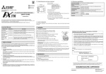
The following program example sets the voltage output mode, and a digital value in D0 is converted to
analog.
The following program example sets the current output mode, and a digital value in D2 is converted to
analog.
Record
meter, etc.
M8114
D2
4.2.1 Voltage Output Mode
V+
I+
VI-
M8001
D0
5.2.2 Current Output Mode
AG
The value of D0 is given as a multiple of five.
K2
M8000
*1 Inverter, etc.
0
4000
Digital value for analog output (D8114)
If a digital value in the range of 0 ~ 10000 is used in D0, please see below.
FNC 22
MUL
4.2 Wiring
V+
I+
VI-
0
0
10000
Digital value used in user program (D0)
5.2.1 Voltage Output Mode
M8001
Terminal
0
Note:
Drive M8114 which specifies the digital to analog conversion characteristic with M8000 (“a”
type contact of the RUN monitor) or M8001 (“b” type contact of the RUN monitor).
Do not change the ON/OFF state while the digital to analog conversion is operating.
The Digital to analog conversion is not executed correctly when M8114 is turned ON and OFF
during the conversion process.
•
Analog
output
Digital value used in user program: (D8114) = 2 × D0 ÷ 5
5.2 Basic Example Program
4.1 Applicable cables
Use AWG26 ~ 16 for connection with output equipment.
10V
Digital value for
analog output
(D8114)
Note:
terminal.
•
4000
Description
M8114
Never solder the end of any cables.
Make sure that the number of connected cables is not more than the unit has been
designed for.
FX1N-1DA-BD
In voltage output mode, the 1DA converts digital values from 0 ~ 4000 to the analog output of 0 ~ 10 Volts.
If using a digital range of 0 ~ 10000 in the program, the range must be converted to 0 ~ 4000 as shown in
the programming example below. Digital values for conversion to analog are stored in D8114.
The analog output does not have exact resolution of 2.5mV because the digital value is converted from 0
~ 10000 to a range of 0 ~ 4000.
Table 5.1: Allocation of Device
Note:
•
5.3.1 Example Application Program 1
5. Example Program
0
0
A
Digital value used in user program (D60)
0
2000
Digital value for analog output (D8114)
If a digital value in the range of 0 ~ A is used in D60, please see below.
Digital value used in user program: D8114 = 2000 × D60 ÷ A
= 2000 × D60 ÷ 10000 (In A = 10000 case)
= D60 ÷ 5
The value of D60 is given as a multiple of five
M8000
M8114
FNC 23
DIV
D60
K5
FNC 12
MOV
D62
D8114
D62
Manual number : JY992D96401
Manual revision : A
Date
: May 2001
HEAD OFFICE : MITSUBISHI DENKI BLDG MARUNOUTI TOKYO 100-8310
HIMEJI WORKS : 840, CHIYODA CHO, HIMEJI, JAPAN
TELEX : J24532 CABLE MELCO TOKYO
4. Wiring
Caution:
Cut off all phases of power source before installing / removing or performing wiring work on
the expansion board in order to avoid electric shock or damage of product.
•
•
An analog output is converted from a digital value (D8114) using the DA conversion characteristic
specified by special auxiliary relay M8114 at each END instruction.
5.1 Allocated Device
Do not lay signal cable near to high voltage power cable or house them in the same
trunking duct. Effects of noise or surge induction may occur. Keep signal cables a safe
distance of more than 100 mm (3.94") from these power cables.
Ground the shied wire or the shield of a shielded cable. Do not, however, ground at the
same point as high voltage lines.
Device
•
Never connect cables of a non permitted size.
•
Fix cables so that any stress is not directly applied on the terminal block or the cable
connection area.
•
The terminal tightening torque is 0.5 ~ 0.6 Nžm. Tighten securely to avoid malfunction.
•
Do not use to the
•
Switch of output mode
OFF: Voltage output mode (0 ~ 10V)
ON:
Current output mode (4 ~ 20mA)
D8114
Digital value (When power supply is turned ON, D8114 will initials to “0”.)
This D/A conversion is done regardless of the RUN/STOP status of the PLC. Any time power
is supplied to the PLC when the 1DA is attached, the analog value in D8114 will be output.
The analog output value will continue to be output when the PLC status is changed from RUN
to STOP!
The maximum tightening torque is 0.5 ~ 0.6 N•m.
•
When using a different type of cable, defective contact at the terminal is possible. Use a crimp
terminal to achieve a good contact.
Table 4.1: Liner and Sectional Area
Linear
Sectional
Area (mm2)
AWG26
0.1288
:
:
:
:
AWG16
1.309
Stranded cable: Remove sheath, twist
core wires, then connect cable.
Single cable: Remove sheath, then
connect cable.
FNC 23
D DIV
D2
K5
D4
FNC 12
MOV
D4
D8114
M8114
Set in voltage output mode (0 ~ 10V).
5.3.2 Example Application Program 2
FNC 12
MOV
6mm
D0*1
D8114
D0*1 is converted digital value to analog output.
*1 If a digital value is not stored in D0, D8114 can be used directly for other instructions.
M8000
M8114
FNC 12
MOV
Grounding resistance of
100Ω or less (Class D)
D2*1
D8114
Set in current output mode (4 ~ 20mA).
*1 If a digital value is not stored in D2, D8114 can be used directly for other instructions.
4.2.2 Current Output Mode
5.3 Example Application Program
AG
Grounding resistance of
100Ω or less (Class D)
As the 1DA does not have Offset and Gain capabilities, if values are required outside the standard
specification range, additional program commands are required to either multiply or divide the conversion
values. For an example application program, please see FX programming manual II.
Note:
•
•
In current output mode, the 1DA converts digital values from 0 ~ 2000 to the analog output of 0 ~ 20 mA.
If using a digital range of 0 ~ A in the program, the range must be converted to 0 ~ 4000 as shown in the
programming example below. Digital values for conversion to analog are stored in D8114.
The analog output does not have exact resolution of 8 µA because the digital value is converted from 0 ~
A to range of 0 ~ 2000. A > 0.
2000
Accuracy and resolution of the digital to analog conversion are different from the
specification because of the additional program commands.
The original range of the analog output is not changed.
20mA
Digital value for
analog output
(D8114)
Analog
output
4mA
0
D2*1 is converted digital value to analog output.
*1 Connect a 0.1 ~ 0.47µF at 25V DC capacitor in position”*1” when there will be a lot of noise.
FX1N-1DA-BD
M8000
The following program example sets the voltage output mode, and a digital value in D0 is converted to
analog.
The following program example sets the current output mode, and a digital value in D2 is converted to
analog.
Record
meter, etc.
M8114
D2
4.2.1 Voltage Output Mode
V+
I+
VI-
M8001
D0
5.2.2 Current Output Mode
AG
The value of D0 is given as a multiple of five.
K2
M8000
*1 Inverter, etc.
0
4000
Digital value for analog output (D8114)
If a digital value in the range of 0 ~ 10000 is used in D0, please see below.
FNC 22
MUL
4.2 Wiring
V+
I+
VI-
0
0
10000
Digital value used in user program (D0)
5.2.1 Voltage Output Mode
M8001
Terminal
0
Note:
Drive M8114 which specifies the digital to analog conversion characteristic with M8000 (“a”
type contact of the RUN monitor) or M8001 (“b” type contact of the RUN monitor).
Do not change the ON/OFF state while the digital to analog conversion is operating.
The Digital to analog conversion is not executed correctly when M8114 is turned ON and OFF
during the conversion process.
•
Analog
output
Digital value used in user program: (D8114) = 2 × D0 ÷ 5
5.2 Basic Example Program
4.1 Applicable cables
Use AWG26 ~ 16 for connection with output equipment.
10V
Digital value for
analog output
(D8114)
Note:
terminal.
•
4000
Description
M8114
Never solder the end of any cables.
Make sure that the number of connected cables is not more than the unit has been
designed for.
FX1N-1DA-BD
In voltage output mode, the 1DA converts digital values from 0 ~ 4000 to the analog output of 0 ~ 10 Volts.
If using a digital range of 0 ~ 10000 in the program, the range must be converted to 0 ~ 4000 as shown in
the programming example below. Digital values for conversion to analog are stored in D8114.
The analog output does not have exact resolution of 2.5mV because the digital value is converted from 0
~ 10000 to a range of 0 ~ 4000.
Table 5.1: Allocation of Device
Note:
•
5.3.1 Example Application Program 1
5. Example Program
0
0
A
Digital value used in user program (D60)
0
2000
Digital value for analog output (D8114)
If a digital value in the range of 0 ~ A is used in D60, please see below.
Digital value used in user program: D8114 = 2000 × D60 ÷ A
= 2000 × D60 ÷ 10000 (In A = 10000 case)
= D60 ÷ 5
The value of D60 is given as a multiple of five
M8000
M8114
FNC 23
DIV
D60
K5
FNC 12
MOV
D62
D8114
D62
Manual number : JY992D96401
Manual revision : A
Date
: May 2001
HEAD OFFICE : MITSUBISHI DENKI BLDG MARUNOUTI TOKYO 100-8310
HIMEJI WORKS : 840, CHIYODA CHO, HIMEJI, JAPAN
TELEX : J24532 CABLE MELCO TOKYO
2.3 Performance Specifications
1. Introduction
Table 2.1: Performance Specifications
The FX1N-1DA-BD analog output expansion board (hereafter called “1DA” or “expansion board”) is to be
installed in an FX1S or FX1N series PLC, to increase the analog output by 1 point.
FX1N-1DA-BD Analog Output Expansion Board
User’s Manual
JY992D96401A
This manual contains text, diagrams and explanations which will guide the reader in the correct
installation, safe use and operation of the FX1N-1DA-BD Analog Output Expansion Board and should be
read and understood before attempting to install or use the unit. Further information can be found in the
associated manuals list below.
1.1 Features of 1DA
1) Analog output of 1 point can be increased using 1DA. If a 1DA is used, internal mounting in the top of
the PLC means there is no need for a change to the installation area of the PLC.
2) Voltage output (0 ~ 10V) or current output (4 ~ 20mA) for digital to analog conversion can be set by
switching a dedicated special auxiliary relay.
Moreover, the digital value for conversion is stored in a dedicated special data register, as shown in
the table below.
However, the digital to analog conversion characteristics cannot be adjusted.
Table 1.1: Allocated Device
Device
a) Any engineer using the product associated with this manual, should be of a competent nature,
trained and qualified to the local and national standards. These engineers should be fully aware of
all aspects of safety with regards to automated equipment.
M8114
Switch of output mode
OFF: Voltage output mode (0 ~ 10V)
ON:
Current output mode (4 ~ 20mA)
D8114
Digital value for analog output
4 3 (1 .6 9 ")
a )
V +
Note: The term ‘completed equipment’ refers to a third party constructed device which contains or uses
the product associated with this manual.
I+
V I-
Note’s on the Symbols Used in this Manual
b )
At various times through out this manual certain symbols will be used to highlight points of information
which are intended to ensure the users personal safety and protect the integrity of equipment.
Terminal name
Content
•
c )
No connection (DO NOT use this terminal)
V+
Voltage output terminal
I+
Current output terminal
VI-
Common terminal for analog output
b) Mounting holes (2- ∅4.0 / 0.16")
c) Connector for PLC
•
All examples and diagrams shown in this manual are intended only as an aid to understanding the
text, not to guarantee operation. Mitsubishi Electric will accept no responsibility for actual use of the
product based on these illustrative examples.
•
Owing to the very great variety in possible application of this equipment, you must satisfy yourself as
to its suitability for your specific application.
Associated Manual
Manual Name
¤
Description
FX 1S Series
Programmable controllers
Hardware Manual
JY992D83901
FX1N Series
Programmable controllers
Hardware Manual
JY992D89301
Describes contents related to hardware of FX1N
Series PLC, such as specifications, wiring and
installation.
JY992D88101
Describes instructions in FX1S/FX1N/FX2N/FX2NC
series.
FX Series of
Programmable controllers
Programming Manual ΙΙ
¤ Indispensable manual
Describes contents related to hardware of FX1S
Series PLC, such as specifications, wiring and
installation.
12bit binary
Resolution
2.5mV (10V /4000)
8µA {(20mA - 4mA) /2000}
Integrated
accuracy
±1% Against the full scale
(0 ~ 10V: ±0.1V)
±1% Against the full scale
(4 ~ 20mA: ±0.16mA)
D/A conversion
time
1 scan time (Analog to digital conversion is executed at the END instruction).
20mA
Analog
output
4mA
Analog
output
0
Occupied point
0 ~ 2000 are adjusted to 4 ~ 20mA
when the external load is 250Ω.
4000
Digital input
0
2000
Digital input
0 points (1DA is not subject to the standard maximum number of control points in
the host PLC, as it operates via a data register).
Note:
1) When external load resistance is 2kΩ, the overall accuracy of voltage output is adjusted
“±1%”
If external load becomes larger than 2kΩ, the output voltage will increase slightly. When
the load is 1MΩ, the output voltage becomes about 3% higher than the correct value.
2) When using current output, be sure to have an external load resistance of 500Ω or less.
If the load is greater than 500Ω, the output current will be lower than the correct value.
3. Installation
Caution:
1.3 System Configuration
•
Only one expansion board can be used on one FX1S and FX1N PLC main unit.
Do not try to install two or more expansion board. (They will not function)
•
The 1DA cannot be used together with a FX1N-EEPROM-8L or FX1N-5DM.
•
Cut off all phases of power source before installing / removing or performing wiring work
on the expansion board in order to avoid electric shock or damage of product.
•
After the installation and wiring etc. replace the PLCs top cover before power ON.
Note:
1.4 Applicable PLC
Table 1.3: Applicable Programmable Controller
PLC Type
Applicable version
FX1S series
V2.00 or later
FX1N series
V2.00 or later
2. Specifications
Manual
Number
Digital output
Input
characteristics
Table 1.2: Allocation of Terminals
1) Indicates that the identified danger WILL cause physical and property damage.
Under no circumstances will Mitsubishi Electric be liable or responsible for any consequential damage
that may arise as a result of the installation or use of this equipment.
DC 4 ~ 20mA
(External load resistance 500Ω or less)
10V
a) Terminals to connect analog module
The top face of this terminal block is higher than the top face of the
panel cover of the programmable controller by approximately 7mm
(0.28").
b )
c) All operators of the completed equipment should be trained to use that product in a safe and
coordinated manner in compliance to established safety practices.
•
Current output
DC 0 ~ 10V
(External load resistance 2k ~ 1MΩ)
Dimensions: mm (inches) Accessory: Top cover for board ×1,
M3 self-tapping screw ×3 (to fix top cover ×1, to mount board ×2)
b) Any commissioning or service engineer must be of a competent nature, trained and qualified to
the local and national standards.
2) Indicates that the identified danger could POSSIBLY cause physical and property
damage.
Voltage output
0 ~ 4000 are adjusted to 0 ~ 10V when
the external load is 2kΩ.
1.2 External Dimensions and Each Part Name
3 8 .5 (1 .5 2 ")
This manual has been written to be used by trained and competent personnel. The definition of such a
person or persons is as follows:
Range of analog
output
Description
Specifications are subject to change without notice
Guidelines for the Safety of the User and Protection of the
FX1N-1DA-BD Analog Output Expansion Board.
Specification
Item
2.1 General Specifications
Same as the programmable controller main unit. (Refer to the programmable controller main unit manual)
2.2 Power Supply Specifications
Power supplied by internal feed of the programmable controller main unit.
•
Securely install the expansion board, and fix to the PLC. Defective contact can cause
malfunction.
•
The tightening torque for fixing the board or top cover is 0.3 ~ 0.6 Nžm. Tighten securely to
avoid malfunction.
Note:
Only one expansion board can be used per main unit of FX1S and FX1N series PLC. Do not try
to install two or more expansion boards.
Moreover, the 1DA cannot be used with the FX1N-EEPROM-8L or FX1N-5DM.
The following is a generic explanation of how to install an expansion board
to the PLC.
a )'
a )
a) Top cover for expansion board
c )
b) M3 self-tapping screw to mount expansion board
c) M3 self-tapping screw to fix top cover
b )
e )
c )
d) External port for optional equipment
e) Expansion board
Note: Do not remove this screw.
d )
N o te )
1) Remove the top cover of the main unit and keep.
2) Plug expansion board “e)” into the external port “d)”.
3) Fix expansion board to main unit using M3 self-tapping screws “c)”. (Tightening torque: 0.3 ~ 0.6N⋅m)
4) Attach top cover for expansion board “a)” removing section “a)’” to expose connector etc.
5) Secure top cover with M3 self-tapping screw “b)”. (Tightening torque: 0.3 ~ 0.6N⋅m)
4. Wiring
Caution:
Cut off all phases of power source before installing / removing or performing wiring work on
the expansion board in order to avoid electric shock or damage of product.
•
•
An analog output is converted from a digital value (D8114) using the DA conversion characteristic
specified by special auxiliary relay M8114 at each END instruction.
5.1 Allocated Device
Do not lay signal cable near to high voltage power cable or house them in the same
trunking duct. Effects of noise or surge induction may occur. Keep signal cables a safe
distance of more than 100 mm (3.94") from these power cables.
Ground the shied wire or the shield of a shielded cable. Do not, however, ground at the
same point as high voltage lines.
Device
•
Never connect cables of a non permitted size.
•
Fix cables so that any stress is not directly applied on the terminal block or the cable
connection area.
•
The terminal tightening torque is 0.5 ~ 0.6 Nžm. Tighten securely to avoid malfunction.
•
Do not use to the
•
Switch of output mode
OFF: Voltage output mode (0 ~ 10V)
ON:
Current output mode (4 ~ 20mA)
D8114
Digital value (When power supply is turned ON, D8114 will initials to “0”.)
This D/A conversion is done regardless of the RUN/STOP status of the PLC. Any time power
is supplied to the PLC when the 1DA is attached, the analog value in D8114 will be output.
The analog output value will continue to be output when the PLC status is changed from RUN
to STOP!
The maximum tightening torque is 0.5 ~ 0.6 N•m.
•
When using a different type of cable, defective contact at the terminal is possible. Use a crimp
terminal to achieve a good contact.
Table 4.1: Liner and Sectional Area
Linear
Sectional
Area (mm2)
AWG26
0.1288
:
:
:
:
AWG16
1.309
Stranded cable: Remove sheath, twist
core wires, then connect cable.
Single cable: Remove sheath, then
connect cable.
FNC 23
D DIV
D2
K5
D4
FNC 12
MOV
D4
D8114
M8114
Set in voltage output mode (0 ~ 10V).
5.3.2 Example Application Program 2
FNC 12
MOV
6mm
D0*1
D8114
D0*1 is converted digital value to analog output.
*1 If a digital value is not stored in D0, D8114 can be used directly for other instructions.
M8000
M8114
FNC 12
MOV
Grounding resistance of
100Ω or less (Class D)
D2*1
D8114
Set in current output mode (4 ~ 20mA).
*1 If a digital value is not stored in D2, D8114 can be used directly for other instructions.
4.2.2 Current Output Mode
5.3 Example Application Program
AG
Grounding resistance of
100Ω or less (Class D)
As the 1DA does not have Offset and Gain capabilities, if values are required outside the standard
specification range, additional program commands are required to either multiply or divide the conversion
values. For an example application program, please see FX programming manual II.
Note:
•
•
In current output mode, the 1DA converts digital values from 0 ~ 2000 to the analog output of 0 ~ 20 mA.
If using a digital range of 0 ~ A in the program, the range must be converted to 0 ~ 4000 as shown in the
programming example below. Digital values for conversion to analog are stored in D8114.
The analog output does not have exact resolution of 8 µA because the digital value is converted from 0 ~
A to range of 0 ~ 2000. A > 0.
2000
Accuracy and resolution of the digital to analog conversion are different from the
specification because of the additional program commands.
The original range of the analog output is not changed.
20mA
Digital value for
analog output
(D8114)
Analog
output
4mA
0
D2*1 is converted digital value to analog output.
*1 Connect a 0.1 ~ 0.47µF at 25V DC capacitor in position”*1” when there will be a lot of noise.
FX1N-1DA-BD
M8000
The following program example sets the voltage output mode, and a digital value in D0 is converted to
analog.
The following program example sets the current output mode, and a digital value in D2 is converted to
analog.
Record
meter, etc.
M8114
D2
4.2.1 Voltage Output Mode
V+
I+
VI-
M8001
D0
5.2.2 Current Output Mode
AG
The value of D0 is given as a multiple of five.
K2
M8000
*1 Inverter, etc.
0
4000
Digital value for analog output (D8114)
If a digital value in the range of 0 ~ 10000 is used in D0, please see below.
FNC 22
MUL
4.2 Wiring
V+
I+
VI-
0
0
10000
Digital value used in user program (D0)
5.2.1 Voltage Output Mode
M8001
Terminal
0
Note:
Drive M8114 which specifies the digital to analog conversion characteristic with M8000 (“a”
type contact of the RUN monitor) or M8001 (“b” type contact of the RUN monitor).
Do not change the ON/OFF state while the digital to analog conversion is operating.
The Digital to analog conversion is not executed correctly when M8114 is turned ON and OFF
during the conversion process.
•
Analog
output
Digital value used in user program: (D8114) = 2 × D0 ÷ 5
5.2 Basic Example Program
4.1 Applicable cables
Use AWG26 ~ 16 for connection with output equipment.
10V
Digital value for
analog output
(D8114)
Note:
terminal.
•
4000
Description
M8114
Never solder the end of any cables.
Make sure that the number of connected cables is not more than the unit has been
designed for.
FX1N-1DA-BD
In voltage output mode, the 1DA converts digital values from 0 ~ 4000 to the analog output of 0 ~ 10 Volts.
If using a digital range of 0 ~ 10000 in the program, the range must be converted to 0 ~ 4000 as shown in
the programming example below. Digital values for conversion to analog are stored in D8114.
The analog output does not have exact resolution of 2.5mV because the digital value is converted from 0
~ 10000 to a range of 0 ~ 4000.
Table 5.1: Allocation of Device
Note:
•
5.3.1 Example Application Program 1
5. Example Program
0
0
A
Digital value used in user program (D60)
0
2000
Digital value for analog output (D8114)
If a digital value in the range of 0 ~ A is used in D60, please see below.
Digital value used in user program: D8114 = 2000 × D60 ÷ A
= 2000 × D60 ÷ 10000 (In A = 10000 case)
= D60 ÷ 5
The value of D60 is given as a multiple of five
M8000
M8114
FNC 23
DIV
D60
K5
FNC 12
MOV
D62
D8114
D62
Manual number : JY992D96401
Manual revision : A
Date
: May 2001
HEAD OFFICE : MITSUBISHI DENKI BLDG MARUNOUTI TOKYO 100-8310
HIMEJI WORKS : 840, CHIYODA CHO, HIMEJI, JAPAN
TELEX : J24532 CABLE MELCO TOKYO