1
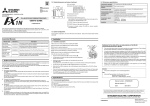
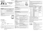
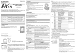
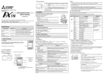
1.2 Outside dimensions and name of each part
Side
B
Side
Side
A JAPANESE
3. Specifications
Unit: mm (inches)
B ENGLISH
43 (1.69)
➀ ➃SD ➄ RD
SG
38.5 (1.52)
FX1N-485-BD RS-485 COMMUNICATION BOARD
RDA RDB SDA SDB
➂
USER’S GUIDE
➀
➁
➅
3.1 Environmental specifications
Accessories: Top cover for board 1
Terminal resistor 330Ω 2
Terminal resistor 110Ω 1
M3 screw to mount board 2
M3 screw to fix top cover 1
Station No. label for link
The environmental specifications are equivalent to those of the PLC main unit. (Refer to the manual of the
PLC main unit.)
3.2 Power supply specifications
5V DC, 60 mA is supplied as the power from the PLC.
➀ Mounting hole (2-φ3.5)
3.3 Performance specifications
➁ Connector for PLC
Transmission standard
In conformance to RS-485 and RS-422
Maximum transmission
distance
50m (164ft) maximum
➃ SD LED: Flickers at high speed during send.
Communication type
No protocol communication, Computer link (dedicated protocol),
parallel link, N:N network
➄ RD LED: Flickers at high speed during receive.
Communication method
Half duplex, bi-directional
➅ Connector
Communication
procedure
No protocol communication, Computer link (dedicated protocol 1,
dedicated protocol 4), parallel link, N:N network
Transmission speed
(baud rate)
No protocol communication, Computer link (dedicated protocol): 300 to
19200 bps
Parallel link: 19200(bps)
N:N network: 38400(bps)
Insulation
None
➂ Terminal block for RS-485 equipment
The top face of this terminal box is higher than the top face of the
PLC panel cover by approximately 7 mm.
JY992D84201C
This manual only describes the specifications for RS-485 Communication Board FX1N-485-BD.
For complete operation, wiring, mounting and programming instructions please refer to the FX1S, FX1N
HARDWARE MANUAL and PROGRAMMING MANUAL.
These manuals should be read and understood before attempting to install or use the unit.
for display module FX1N-5DM or memory cassette
FX1N-EEPROM-8L
1.3 System configuration
For the system configuration, refer to the FX Series User's Manual - Data Communication Edition offered
separately.
Associated Manuals
Manual No.
Description
FX1S Series
Hardware Manual
Manual name
JY992D83901
Describes contents related to hardware of FX1S Series PLC such
as specifications, wiring and installation.
FX1N Series
Hardware Manual
JY992D88201
Describes contents related to hardware of FX1N Series PLC such
as specifications, wiring and installation.
FX Programming
Manual II
JY992D88101
Describes instructions in FX1S/FX1N/FX2N/FX2NC Series.
FX Series User's
Manual - Data
Communication
Edition
JY997D16901
2. Installation
2.1 Installation procedure
Make sure to turn off the power before installing the 485BD.
A) Communication board 485BD (function expansion board)
D)
D)'
E)
B) Connector for optional equipment
Describes contents related to communication available in FX
Series PLC such as wiring, communication setting and program
examples. (Make sure to read this manual.)
C)
C) M3 screw to fix board (2 pieces) (offered as accessories of board)
D) Top cover for board (offered as an accessory of board)
A)
C)
E) M3 screw to fix top cover (offered as an accessory of board)
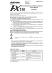
Guidelines for the safety of the user and protection of the RS-485
Communication Board FX1N-485-BD
Note: Do not remove this screw of FX1S.
1. Outline of Product
•
Plug the communication board A) in to the connector B).
•
The RS-485 communication board FX1N-485-BD (hereafter referred to as "485BD") is connected to the
FX1S/FX1N Series PLC basic unit, and available for the applications described below.
Only one function expansion board can be connected to one PLC basic unit. Accordingly, the 485BD cannot
be used together with the FX1N-422-BD or the FX1N-232-BD.
Fix the board to the basic unit with two M3 screws C). (Tightening
torque: 0.3 to 0.6 Nxm)
•
Remove the top cover of the basic unit, and attach the top cover for
board D) instead.
During attachment, remove D)’ with a nipper, etc. so that the connector of the board is exposed.
1.1 Features
•
Fix the top cover with the M3 screw E). (Tightening torque: 0.3 to 0.6 Nxm)
1) No protocol communication.
The 485BD transfers the data using the RS instruction between a bar code reader, personal computer
or printer.
As the 485BD is not equipped with buffer memory, it sends and receives the data using data registers
specified by the RS instruction.
For the RS instruction and the communication setting, refer to the FX Series User's Manual - Data
Communication Edition.
•
When the FX1N-5DM is used also, refer to the Hardware manual offered with the FX1S/FX1N Series
PLC main unit.
•
Only one function expansion board is available for one FX1S/FX1N Series PLC basic unit. Never stack
up two or more function expansion boards. (Even if they are stacked up, they do not function at all.)
•
The 485BD can be used with the FX1N-EEPROM-8L only for program transfer.
(The FX1N-EEPROM-8L cannnot be connected continuously.)
B)
•
This manual has been written to be used by trained and competent personnel. This is defined
by the European directives for machinery, low voltage and EMC.
•
If in doubt at any stage during the installation of the RS-485 Communication Board FX1N-485BD always consult a professional electrical engineer who is qualified and trained to the local
and national standards. If in doubt about the operation or use of the RS-485 Communication
Board FX1N-485-BD please consult the nearest Mitsubishi Electric distributor.
•
Under no circumstances will Mitsubishi Electric be liable or responsible for any consequential
damage that may arise as a result of the installation or use of this equipment.
•
All examples and diagrams shown in this manual are intended only as an aid to understanding
the text, not to guarantee operation. Mitsubishi Electric will accept no responsibility for actual
use of the product based on these illustrative examples.
•
Owing to the very great variety in possible application of this equipment, you must satisfy
yourself as to its suitability for your specific application.
Note)
2) Computer link by dedicated protocol.
The 485BD transfers the data when a personal computer directly specifies devices of the PLC.
For the dedicated protocol and the communication setting, refer to the FX Series User's Manual - Data
Communication Edition.
Manual number : JY992D84201
3) Parallel link.
The 485BD transfers automatically auxiliary relays and data registers when two FX1S Series PLC’s or
two FX1N Series PLC’s are connected on a one-to-one basis.
For the setting procedure and program examples, refer to the FX Series User's Manual - Data Communication Edition.
4) N:N network.
The 485BD transfers automatically up to 64 auxiliary relays and 8 data registers when up to eight FX1S/
FX1N Series PLC units are connected. For the setting procedure and program examples, refer to the
FX Series User's Manual - Data Communication Edition.
Manual revision : C
Date
: AUGUST 2006
This manual confers no industrial property rights or any rights of any other kind, nor does it confer any
patent licenses. Mitsubishi Electric Corporation cannot be held responsible for any problems involving
industrial property rights which may occur as a result of using the contents noted in this manual.
HEAD OFFICE : TOKYO BUILDING, 2-7-3 MARUNOUCHI, CHIYODA-KU, TOKYO 100-8310, JAPAN
HIMEJI WORKS : 840, CHIYODA CHO, HIMEJI, JAPAN
JY992D84201C
Effective Aug. 2006
Specifications are subject to
change without notice
1.2 Outside dimensions and name of each part
Side
B
Side
Side
A JAPANESE
3. Specifications
Unit: mm (inches)
B ENGLISH
43 (1.69)
➀ ➃SD ➄ RD
SG
38.5 (1.52)
FX1N-485-BD RS-485 COMMUNICATION BOARD
RDA RDB SDA SDB
➂
USER’S GUIDE
➀
➁
➅
3.1 Environmental specifications
Accessories: Top cover for board 1
Terminal resistor 330Ω 2
Terminal resistor 110Ω 1
M3 screw to mount board 2
M3 screw to fix top cover 1
Station No. label for link
The environmental specifications are equivalent to those of the PLC main unit. (Refer to the manual of the
PLC main unit.)
3.2 Power supply specifications
5V DC, 60 mA is supplied as the power from the PLC.
➀ Mounting hole (2-φ3.5)
3.3 Performance specifications
➁ Connector for PLC
Transmission standard
In conformance to RS-485 and RS-422
Maximum transmission
distance
50m (164ft) maximum
➃ SD LED: Flickers at high speed during send.
Communication type
No protocol communication, Computer link (dedicated protocol),
parallel link, N:N network
➄ RD LED: Flickers at high speed during receive.
Communication method
Half duplex, bi-directional
➅ Connector
Communication
procedure
No protocol communication, Computer link (dedicated protocol 1,
dedicated protocol 4), parallel link, N:N network
Transmission speed
(baud rate)
No protocol communication, Computer link (dedicated protocol): 300 to
19200 bps
Parallel link: 19200(bps)
N:N network: 38400(bps)
Insulation
None
➂ Terminal block for RS-485 equipment
The top face of this terminal box is higher than the top face of the
PLC panel cover by approximately 7 mm.
JY992D84201C
This manual only describes the specifications for RS-485 Communication Board FX1N-485-BD.
For complete operation, wiring, mounting and programming instructions please refer to the FX1S, FX1N
HARDWARE MANUAL and PROGRAMMING MANUAL.
These manuals should be read and understood before attempting to install or use the unit.
for display module FX1N-5DM or memory cassette
FX1N-EEPROM-8L
1.3 System configuration
For the system configuration, refer to the FX Series User's Manual - Data Communication Edition offered
separately.
Associated Manuals
Manual No.
Description
FX1S Series
Hardware Manual
Manual name
JY992D83901
Describes contents related to hardware of FX1S Series PLC such
as specifications, wiring and installation.
FX1N Series
Hardware Manual
JY992D88201
Describes contents related to hardware of FX1N Series PLC such
as specifications, wiring and installation.
FX Programming
Manual II
JY992D88101
Describes instructions in FX1S/FX1N/FX2N/FX2NC Series.
FX Series User's
Manual - Data
Communication
Edition
JY997D16901
2. Installation
2.1 Installation procedure
Make sure to turn off the power before installing the 485BD.
A) Communication board 485BD (function expansion board)
D)
D)'
E)
B) Connector for optional equipment
Describes contents related to communication available in FX
Series PLC such as wiring, communication setting and program
examples. (Make sure to read this manual.)
C)
C) M3 screw to fix board (2 pieces) (offered as accessories of board)
D) Top cover for board (offered as an accessory of board)
A)
C)
E) M3 screw to fix top cover (offered as an accessory of board)
Guidelines for the safety of the user and protection of the RS-485
Communication Board FX1N-485-BD
Note: Do not remove this screw of FX1S.
1. Outline of Product
•
Plug the communication board A) in to the connector B).
•
The RS-485 communication board FX1N-485-BD (hereafter referred to as "485BD") is connected to the
FX1S/FX1N Series PLC basic unit, and available for the applications described below.
Only one function expansion board can be connected to one PLC basic unit. Accordingly, the 485BD cannot
be used together with the FX1N-422-BD or the FX1N-232-BD.
Fix the board to the basic unit with two M3 screws C). (Tightening
torque: 0.3 to 0.6 Nxm)
•
Remove the top cover of the basic unit, and attach the top cover for
board D) instead.
During attachment, remove D)’ with a nipper, etc. so that the connector of the board is exposed.
1.1 Features
•
Fix the top cover with the M3 screw E). (Tightening torque: 0.3 to 0.6 Nxm)
1) No protocol communication.
The 485BD transfers the data using the RS instruction between a bar code reader, personal computer
or printer.
As the 485BD is not equipped with buffer memory, it sends and receives the data using data registers
specified by the RS instruction.
For the RS instruction and the communication setting, refer to the FX Series User's Manual - Data
Communication Edition.
•
When the FX1N-5DM is used also, refer to the Hardware manual offered with the FX1S/FX1N Series
PLC main unit.
•
Only one function expansion board is available for one FX1S/FX1N Series PLC basic unit. Never stack
up two or more function expansion boards. (Even if they are stacked up, they do not function at all.)
•
The 485BD can be used with the FX1N-EEPROM-8L only for program transfer.
(The FX1N-EEPROM-8L cannnot be connected continuously.)
B)
•
This manual has been written to be used by trained and competent personnel. This is defined
by the European directives for machinery, low voltage and EMC.
•
If in doubt at any stage during the installation of the RS-485 Communication Board FX1N-485BD always consult a professional electrical engineer who is qualified and trained to the local
and national standards. If in doubt about the operation or use of the RS-485 Communication
Board FX1N-485-BD please consult the nearest Mitsubishi Electric distributor.
•
Under no circumstances will Mitsubishi Electric be liable or responsible for any consequential
damage that may arise as a result of the installation or use of this equipment.
•
All examples and diagrams shown in this manual are intended only as an aid to understanding
the text, not to guarantee operation. Mitsubishi Electric will accept no responsibility for actual
use of the product based on these illustrative examples.
•
Owing to the very great variety in possible application of this equipment, you must satisfy
yourself as to its suitability for your specific application.
Note)
2) Computer link by dedicated protocol.
The 485BD transfers the data when a personal computer directly specifies devices of the PLC.
For the dedicated protocol and the communication setting, refer to the FX Series User's Manual - Data
Communication Edition.
Manual number : JY992D84201
3) Parallel link.
The 485BD transfers automatically auxiliary relays and data registers when two FX1S Series PLC’s or
two FX1N Series PLC’s are connected on a one-to-one basis.
For the setting procedure and program examples, refer to the FX Series User's Manual - Data Communication Edition.
4) N:N network.
The 485BD transfers automatically up to 64 auxiliary relays and 8 data registers when up to eight FX1S/
FX1N Series PLC units are connected. For the setting procedure and program examples, refer to the
FX Series User's Manual - Data Communication Edition.
Manual revision : C
Date
: AUGUST 2006
This manual confers no industrial property rights or any rights of any other kind, nor does it confer any
patent licenses. Mitsubishi Electric Corporation cannot be held responsible for any problems involving
industrial property rights which may occur as a result of using the contents noted in this manual.
HEAD OFFICE : TOKYO BUILDING, 2-7-3 MARUNOUCHI, CHIYODA-KU, TOKYO 100-8310, JAPAN
HIMEJI WORKS : 840, CHIYODA CHO, HIMEJI, JAPAN
JY992D84201C
Effective Aug. 2006
Specifications are subject to
change without notice
1.2 Outside dimensions and name of each part
Side
B
Side
Side
A JAPANESE
3. Specifications
Unit: mm (inches)
B ENGLISH
43 (1.69)
➀ ➃SD ➄ RD
SG
38.5 (1.52)
FX1N-485-BD RS-485 COMMUNICATION BOARD
RDA RDB SDA SDB
➂
USER’S GUIDE
➀
➁
➅
3.1 Environmental specifications
Accessories: Top cover for board 1
Terminal resistor 330Ω 2
Terminal resistor 110Ω 1
M3 screw to mount board 2
M3 screw to fix top cover 1
Station No. label for link
The environmental specifications are equivalent to those of the PLC main unit. (Refer to the manual of the
PLC main unit.)
3.2 Power supply specifications
5V DC, 60 mA is supplied as the power from the PLC.
➀ Mounting hole (2-φ3.5)
3.3 Performance specifications
➁ Connector for PLC
Transmission standard
In conformance to RS-485 and RS-422
Maximum transmission
distance
50m (164ft) maximum
➃ SD LED: Flickers at high speed during send.
Communication type
No protocol communication, Computer link (dedicated protocol),
parallel link, N:N network
➄ RD LED: Flickers at high speed during receive.
Communication method
Half duplex, bi-directional
➅ Connector
Communication
procedure
No protocol communication, Computer link (dedicated protocol 1,
dedicated protocol 4), parallel link, N:N network
Transmission speed
(baud rate)
No protocol communication, Computer link (dedicated protocol): 300 to
19200 bps
Parallel link: 19200(bps)
N:N network: 38400(bps)
Insulation
None
➂ Terminal block for RS-485 equipment
The top face of this terminal box is higher than the top face of the
PLC panel cover by approximately 7 mm.
JY992D84201C
This manual only describes the specifications for RS-485 Communication Board FX1N-485-BD.
For complete operation, wiring, mounting and programming instructions please refer to the FX1S, FX1N
HARDWARE MANUAL and PROGRAMMING MANUAL.
These manuals should be read and understood before attempting to install or use the unit.
for display module FX1N-5DM or memory cassette
FX1N-EEPROM-8L
1.3 System configuration
For the system configuration, refer to the FX Series User's Manual - Data Communication Edition offered
separately.
Associated Manuals
Manual No.
Description
FX1S Series
Hardware Manual
Manual name
JY992D83901
Describes contents related to hardware of FX1S Series PLC such
as specifications, wiring and installation.
FX1N Series
Hardware Manual
JY992D88201
Describes contents related to hardware of FX1N Series PLC such
as specifications, wiring and installation.
FX Programming
Manual II
JY992D88101
Describes instructions in FX1S/FX1N/FX2N/FX2NC Series.
FX Series User's
Manual - Data
Communication
Edition
JY997D16901
2. Installation
2.1 Installation procedure
Make sure to turn off the power before installing the 485BD.
A) Communication board 485BD (function expansion board)
D)
D)'
E)
B) Connector for optional equipment
Describes contents related to communication available in FX
Series PLC such as wiring, communication setting and program
examples. (Make sure to read this manual.)
C)
C) M3 screw to fix board (2 pieces) (offered as accessories of board)
D) Top cover for board (offered as an accessory of board)
A)
C)
E) M3 screw to fix top cover (offered as an accessory of board)
Guidelines for the safety of the user and protection of the RS-485
Communication Board FX1N-485-BD
Note: Do not remove this screw of FX1S.
1. Outline of Product
•
Plug the communication board A) in to the connector B).
•
The RS-485 communication board FX1N-485-BD (hereafter referred to as "485BD") is connected to the
FX1S/FX1N Series PLC basic unit, and available for the applications described below.
Only one function expansion board can be connected to one PLC basic unit. Accordingly, the 485BD cannot
be used together with the FX1N-422-BD or the FX1N-232-BD.
Fix the board to the basic unit with two M3 screws C). (Tightening
torque: 0.3 to 0.6 Nxm)
•
Remove the top cover of the basic unit, and attach the top cover for
board D) instead.
During attachment, remove D)’ with a nipper, etc. so that the connector of the board is exposed.
1.1 Features
•
Fix the top cover with the M3 screw E). (Tightening torque: 0.3 to 0.6 Nxm)
1) No protocol communication.
The 485BD transfers the data using the RS instruction between a bar code reader, personal computer
or printer.
As the 485BD is not equipped with buffer memory, it sends and receives the data using data registers
specified by the RS instruction.
For the RS instruction and the communication setting, refer to the FX Series User's Manual - Data
Communication Edition.
•
When the FX1N-5DM is used also, refer to the Hardware manual offered with the FX1S/FX1N Series
PLC main unit.
•
Only one function expansion board is available for one FX1S/FX1N Series PLC basic unit. Never stack
up two or more function expansion boards. (Even if they are stacked up, they do not function at all.)
•
The 485BD can be used with the FX1N-EEPROM-8L only for program transfer.
(The FX1N-EEPROM-8L cannnot be connected continuously.)
B)
•
This manual has been written to be used by trained and competent personnel. This is defined
by the European directives for machinery, low voltage and EMC.
•
If in doubt at any stage during the installation of the RS-485 Communication Board FX1N-485BD always consult a professional electrical engineer who is qualified and trained to the local
and national standards. If in doubt about the operation or use of the RS-485 Communication
Board FX1N-485-BD please consult the nearest Mitsubishi Electric distributor.
•
Under no circumstances will Mitsubishi Electric be liable or responsible for any consequential
damage that may arise as a result of the installation or use of this equipment.
•
All examples and diagrams shown in this manual are intended only as an aid to understanding
the text, not to guarantee operation. Mitsubishi Electric will accept no responsibility for actual
use of the product based on these illustrative examples.
•
Owing to the very great variety in possible application of this equipment, you must satisfy
yourself as to its suitability for your specific application.
Note)
2) Computer link by dedicated protocol.
The 485BD transfers the data when a personal computer directly specifies devices of the PLC.
For the dedicated protocol and the communication setting, refer to the FX Series User's Manual - Data
Communication Edition.
Manual number : JY992D84201
3) Parallel link.
The 485BD transfers automatically auxiliary relays and data registers when two FX1S Series PLC’s or
two FX1N Series PLC’s are connected on a one-to-one basis.
For the setting procedure and program examples, refer to the FX Series User's Manual - Data Communication Edition.
4) N:N network.
The 485BD transfers automatically up to 64 auxiliary relays and 8 data registers when up to eight FX1S/
FX1N Series PLC units are connected. For the setting procedure and program examples, refer to the
FX Series User's Manual - Data Communication Edition.
Manual revision : C
Date
: AUGUST 2006
This manual confers no industrial property rights or any rights of any other kind, nor does it confer any
patent licenses. Mitsubishi Electric Corporation cannot be held responsible for any problems involving
industrial property rights which may occur as a result of using the contents noted in this manual.
HEAD OFFICE : TOKYO BUILDING, 2-7-3 MARUNOUCHI, CHIYODA-KU, TOKYO 100-8310, JAPAN
HIMEJI WORKS : 840, CHIYODA CHO, HIMEJI, JAPAN
JY992D84201C
Effective Aug. 2006
Specifications are subject to
change without notice
1.2 Outside dimensions and name of each part
Side
B
Side
Side
A JAPANESE
3. Specifications
Unit: mm (inches)
B ENGLISH
43 (1.69)
➀ ➃SD ➄ RD
SG
38.5 (1.52)
FX1N-485-BD RS-485 COMMUNICATION BOARD
RDA RDB SDA SDB
➂
USER’S GUIDE
➀
➁
➅
3.1 Environmental specifications
Accessories: Top cover for board 1
Terminal resistor 330Ω 2
Terminal resistor 110Ω 1
M3 screw to mount board 2
M3 screw to fix top cover 1
Station No. label for link
The environmental specifications are equivalent to those of the PLC main unit. (Refer to the manual of the
PLC main unit.)
3.2 Power supply specifications
5V DC, 60 mA is supplied as the power from the PLC.
➀ Mounting hole (2-φ3.5)
3.3 Performance specifications
➁ Connector for PLC
Transmission standard
In conformance to RS-485 and RS-422
Maximum transmission
distance
50m (164ft) maximum
➃ SD LED: Flickers at high speed during send.
Communication type
No protocol communication, Computer link (dedicated protocol),
parallel link, N:N network
➄ RD LED: Flickers at high speed during receive.
Communication method
Half duplex, bi-directional
➅ Connector
Communication
procedure
No protocol communication, Computer link (dedicated protocol 1,
dedicated protocol 4), parallel link, N:N network
Transmission speed
(baud rate)
No protocol communication, Computer link (dedicated protocol): 300 to
19200 bps
Parallel link: 19200(bps)
N:N network: 38400(bps)
Insulation
None
➂ Terminal block for RS-485 equipment
The top face of this terminal box is higher than the top face of the
PLC panel cover by approximately 7 mm.
JY992D84201C
This manual only describes the specifications for RS-485 Communication Board FX1N-485-BD.
For complete operation, wiring, mounting and programming instructions please refer to the FX1S, FX1N
HARDWARE MANUAL and PROGRAMMING MANUAL.
These manuals should be read and understood before attempting to install or use the unit.
for display module FX1N-5DM or memory cassette
FX1N-EEPROM-8L
1.3 System configuration
For the system configuration, refer to the FX Series User's Manual - Data Communication Edition offered
separately.
Associated Manuals
Manual No.
Description
FX1S Series
Hardware Manual
Manual name
JY992D83901
Describes contents related to hardware of FX1S Series PLC such
as specifications, wiring and installation.
FX1N Series
Hardware Manual
JY992D88201
Describes contents related to hardware of FX1N Series PLC such
as specifications, wiring and installation.
FX Programming
Manual II
JY992D88101
Describes instructions in FX1S/FX1N/FX2N/FX2NC Series.
FX Series User's
Manual - Data
Communication
Edition
JY997D16901
2. Installation
2.1 Installation procedure
Make sure to turn off the power before installing the 485BD.
A) Communication board 485BD (function expansion board)
D)
D)'
E)
B) Connector for optional equipment
Describes contents related to communication available in FX
Series PLC such as wiring, communication setting and program
examples. (Make sure to read this manual.)
C)
C) M3 screw to fix board (2 pieces) (offered as accessories of board)
D) Top cover for board (offered as an accessory of board)
A)
C)
E) M3 screw to fix top cover (offered as an accessory of board)
Guidelines for the safety of the user and protection of the RS-485
Communication Board FX1N-485-BD
Note: Do not remove this screw of FX1S.
1. Outline of Product
•
Plug the communication board A) in to the connector B).
•
The RS-485 communication board FX1N-485-BD (hereafter referred to as "485BD") is connected to the
FX1S/FX1N Series PLC basic unit, and available for the applications described below.
Only one function expansion board can be connected to one PLC basic unit. Accordingly, the 485BD cannot
be used together with the FX1N-422-BD or the FX1N-232-BD.
Fix the board to the basic unit with two M3 screws C). (Tightening
torque: 0.3 to 0.6 Nxm)
•
Remove the top cover of the basic unit, and attach the top cover for
board D) instead.
During attachment, remove D)’ with a nipper, etc. so that the connector of the board is exposed.
1.1 Features
•
Fix the top cover with the M3 screw E). (Tightening torque: 0.3 to 0.6 Nxm)
1) No protocol communication.
The 485BD transfers the data using the RS instruction between a bar code reader, personal computer
or printer.
As the 485BD is not equipped with buffer memory, it sends and receives the data using data registers
specified by the RS instruction.
For the RS instruction and the communication setting, refer to the FX Series User's Manual - Data
Communication Edition.
•
When the FX1N-5DM is used also, refer to the Hardware manual offered with the FX1S/FX1N Series
PLC main unit.
•
Only one function expansion board is available for one FX1S/FX1N Series PLC basic unit. Never stack
up two or more function expansion boards. (Even if they are stacked up, they do not function at all.)
•
The 485BD can be used with the FX1N-EEPROM-8L only for program transfer.
(The FX1N-EEPROM-8L cannnot be connected continuously.)
B)
•
This manual has been written to be used by trained and competent personnel. This is defined
by the European directives for machinery, low voltage and EMC.
•
If in doubt at any stage during the installation of the RS-485 Communication Board FX1N-485BD always consult a professional electrical engineer who is qualified and trained to the local
and national standards. If in doubt about the operation or use of the RS-485 Communication
Board FX1N-485-BD please consult the nearest Mitsubishi Electric distributor.
•
Under no circumstances will Mitsubishi Electric be liable or responsible for any consequential
damage that may arise as a result of the installation or use of this equipment.
•
All examples and diagrams shown in this manual are intended only as an aid to understanding
the text, not to guarantee operation. Mitsubishi Electric will accept no responsibility for actual
use of the product based on these illustrative examples.
•
Owing to the very great variety in possible application of this equipment, you must satisfy
yourself as to its suitability for your specific application.
Note)
2) Computer link by dedicated protocol.
The 485BD transfers the data when a personal computer directly specifies devices of the PLC.
For the dedicated protocol and the communication setting, refer to the FX Series User's Manual - Data
Communication Edition.
Manual number : JY992D84201
3) Parallel link.
The 485BD transfers automatically auxiliary relays and data registers when two FX1S Series PLC’s or
two FX1N Series PLC’s are connected on a one-to-one basis.
For the setting procedure and program examples, refer to the FX Series User's Manual - Data Communication Edition.
4) N:N network.
The 485BD transfers automatically up to 64 auxiliary relays and 8 data registers when up to eight FX1S/
FX1N Series PLC units are connected. For the setting procedure and program examples, refer to the
FX Series User's Manual - Data Communication Edition.
Manual revision : C
Date
: AUGUST 2006
This manual confers no industrial property rights or any rights of any other kind, nor does it confer any
patent licenses. Mitsubishi Electric Corporation cannot be held responsible for any problems involving
industrial property rights which may occur as a result of using the contents noted in this manual.
HEAD OFFICE : TOKYO BUILDING, 2-7-3 MARUNOUCHI, CHIYODA-KU, TOKYO 100-8310, JAPAN
HIMEJI WORKS : 840, CHIYODA CHO, HIMEJI, JAPAN
JY992D84201C
Effective Aug. 2006
Specifications are subject to
change without notice