1
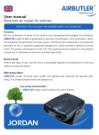
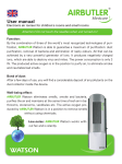
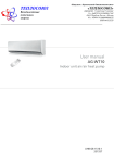
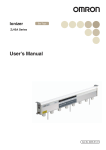
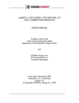
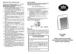
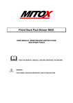
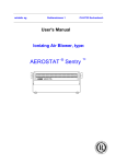
Electrostatic Precipitator ESP 1500 ESP 3000 ESP 4500 TECHNICAL & OPERATION MANUAL 2011 All rights reserved. No part of this publication may be copied or published by means of printing, photocopying, microfilm or otherwise without prior written consent of the manufacturer. This restriction also applies to the corresponding drawings and diagrams. The information given in this document has been collected for the general convenience of our clients. It has been based on general data pertaining to construction material properties and working methods known to us at the time of issue of the document and is therefore subject at any time to change or amendment and the right to change or amend is hereby expressly reserved. The instructions in this publication only serve as a guideline for installation, use, maintenance and repair of the product mentioned on the cover page of this document. This publication is to be used for the standard model of the product of the type given on the cover page. Thus the manufacturer cannot be held responsible for any damage resulting from the application of this publication to the version actually delivered to you. This publication has been written with great care. However, the manufacturer cannot be held responsible, either for any errors occurring in this publication for their consequences. TAKE YOUR TIME TO CAREFULLY READ AND UNDERSTAND THE MANUAL BEFORE USING THE PRODUCT. ALWAYS KEEP THE MANUAL WITH THE PRODUCT. 1 PREFACE Using this manual This manual is intended to be used as a work of reference for professional, well trained and authorised users to be able to safely install, use, maintain and repair the product mentioned on the cover of this document. Please note that it is strongly recommended that training is given by JAKKA Group prior to operatives attempting to carry out maintenance or repair work on this product. Service and technical support For information about specific adjustments, maintenance or repair jobs which are not dealt with in this manual, please contact the supplier of the product. SAFETY INSTRUCTIONS AND WARNINGS 2 General The manufacturer does not accept any liability for the damage to the product or personal injury caused by non-observance of the safety instructions in this manual, or by negligence during installation, use, maintenance and repair of the product mentioned on the cover of this document or corresponding accessories. Specific working conditions or used accessories may require additional safety instructions. Immediately contact your supplier if you detect a potential danger when using the product. The user of the product is always fully responsible for observing the local safety instructions and regulations. Observe all applicable safety instructions and regulations. User manual Everyone working on or with the product must be familiar with the contents of this manual and must strictly observe the instructions therein. The management should instruct the personnel in accordance with the manual and observe all instructions and directions given. Never change the order of the steps to perform Always keep the manual with the product. Pictograms and instructions on the product The pictograms, warning and instructions attached to the product are part of the safety feature. They must not be covered or removed and must be present and legible during the entire life of the product. Immediately replace or repair damaged or illegible pictograms, warnings and instructions . Users The use of this product is exclusively reserved to authorised, trained and qualified users. Temporary personnel and trainees can only use the product under supervision and responsibility of skilled engineers. Intended use The product has been designed exclusively for use in commercial kitchens and for filtering harmful fumes which are released during the most common cooking processes. Using the product for other purposes is considered contrary to its intended use. The manufacturer accepts no liability for any damage or injury resulting from such use. The product has been built in accordance with state-of the-art standards and recognised safety regulations. Only use the product in technically perfect condition with its intended use and the instructions laid down in the user manual. Safety features All safety features must be correctly mounted and can only be removed for maintenance and repair jobs by skilled and authorised service engineers The product must not be used if the safety features are only partly present or defective. The safety features should be regularly checked for their proper functioning, and if required, be immediately repaired. Modifications A modification of the product is not allowed. Technical specifications The specifications given in this manual must not be altered. Safety features All safety features must be correctly mounted and can only be removed for maintenance and repair jobs by skilled and authorised service engineers. The products must not be used if the safety features are not or only partly present, or defective. The safety features should be regularly checked for their proper functioning, and if required, be immediately repaired. Modifications Modification of (parts of) the product is not allowed. Use general WARNING Fire hazard! Never use the product for extracting and/or filtering inflammable, glowing or burning particles or solids or liquids. Never use the product for extracting and/or filtering of aggressive fumes (such as hydrochloric acid) or sharp particles. Inspect the product and check it for damage. Verify the functioning of the safety features. Check the working environment. Do not allow unauthorised persons to enter the working environment. Use common sense. Stay alert and pay attention to your work. Do not use the product when you are tired or under the influence of drugs, alcohol or medicine. Make sure the room is always sufficiently ventilated, particularly in smaller confined areas. Never install the product in front of entrances and exits which must be used by emergency services. Do not use the product at a relative humidity exceeding 80%. Do not use the product at temperatures below 5°C or above 45°C. Keep the operating controls free from dirt and grease. The product is not explosion-proof rated. It can cause sparks and should therefore not be used in areas with an explosion risk. Never operate the product without filters. Do not use the product in areas with high concentrations of dry particulates (dust). Use of ESP 1500/ESP 3000/ESP 4500 for commercial kitchen extraction The product is suitable for the filtration of extracted fumes from commercial kitchens. The product shall always be used in combination with the pre- and post-filters that are suitable for the particular kitchen involved. Service, maintenance and repairs This manual clearly makes a distinction between service maintenance and repair jobs which have to be carried out by the user and those which have to be exclusively carried out by well trained and authorised service engineers. Observe the maintenance intervals given in this manual. Overdue maintenance can lead to high costs for repairs and revisions and can render the guarantee null and void. Always use tools, parts, materials, lubricants and service techniques that have been approved by the manufacturer. Never use worn tools and ensure that tools are not left behind in or on the product. Do not carry out any service, maintenance or repairs on the product before it has been protected against unintended starting. Safety features removed for servicing, maintenance or repair shall be re-installed immediately and checked for proper functioning. Regularly clean the inside of the housing. Clean or replace the filters in time. USED PRODUCTS AND THE ENVIRONMENT Packaging Material The purpose of the packaging is to protect the product during transport. It consists of the following substances that can be reused: - (corrugated) cardboard - untreated wood Do not dispose of the packaging material in the industrial waste Product Products which you would like to dispose of may still contain valuable substances and materials. Do not dispose of the product in the industrial waste. 1 TECHNICAL SPECIFICATIONS 1.1 Technical specifications ESP 1500, ESP 3000 & ESP 4500 Power consumption Max capacity Weight Power Supply Filter efficiency Housing ESP 1500 30W 0.7m 3/s 60 kg ESP 3000 50W 1.4m 3/s 100 kg 220/240 V 50 Hz 1ph 220/240 V 50 Hz 1ph Up to 98% Epoxy-coated steel Up to 98% Epoxy-coated steel 2 GENERAL DESCRIPTION 2.1 ESP 1500/ESP 3000 in kitchen extraction applications ESP 4500 50W 2.1m3 /s 140 kg 220/240 V 50 Hz 1ph Up to 98% Epoxy-coated steel This electrostatic air cleaner can remove, at a high efficiency, small grease and soot particles that pass the grease filters. The ESP 1500/ESP 3000 is designed to be installed in the extraction ducting of a commercial kitchen downstream of the extraction hood. 2.2 Oil drainer It is possible to install an oil drainer in applications for welding of oil-treated steel, oil mist extraction and kitchen fume extraction in order to draw off superfluous liquids from the oil collector. 2.3 Operation Figure 2.1 The extracted contaminated air passes the pre filter (A) that takes out all larger particles. The pre filter also ensures a proper distribution of the airflow. After that, the air passes the ioniser (B). The contaminations in the air are electrically charged by the high voltage (+10kV). These will then be deposited on the earthed plates (see fig. 2.2) by the collector voltage (+5kV). +5kV + + +10kV +5kV + + +5kV Figure 2.2 The final filter (4) is the last filtration step and it also spreads the airflow. There is an on/off switch (D) and a high-voltage indicator (E) on the control panel (see fig. 2.3). Please contact your dealer if the alarm light is illuminated. Regularly check the functioning of the indicator when using the product, since it indicates that the electrostatic filter is properly charged. Figure 2.3 When the product produces a crackling sound, then it could be that the collector and/or ionizer are too dirty and that both need to be cleaned. Switch-off the product with the appropriate switch (D). Wait for at least 10 seconds prior to opening the door that contains the filtration section. Subsequently, clean the collector and ionisation section using warm water and degreasing agent. Check for touching collector plates. Consult your supplier if the plates are bent! Repairs shall only be carried out by JAKKA Group or JAKKA GROUP-authorised staff. Maintenance contracts are available if required. 3 INSTALLATION 3.1 Installation ESP 1500/ESP 3000/ESP 4500 Check that the suspension construction is adequate prior to installing the product. Mount the ESP 1500/ESP 3000/ESP 4500 unit in the ducting system. It can be supported by a suspension bracket (see fig 3.1A) as well as suspension by screw rods attached to the top of the ESP 1500/ESP 3000 unit (see fig. 3.1B). It is necessary to drill holes on the upper side for this purpose. It is also possible to place the unit on the ground. A B Figure 3.1 Please consult the electrical diagram when connecting the air cleaner to the mains. Use suitable rubber or neoprene. Beware of possible differences in the mains power supply. The air cleaner can be stacked to a maximum of four units; the perforations and protrusions on the housing can be used for this purpose. If the buyer wants to exercise warranty for ESP product purchased, it is necessary to ultimate buyer sign a maintenance contract for el. filter with an authorized service JAK-KA Group. Otherwise, the guarantee does not apply to sell the device. 4 DIMENSIONS 4.1 Dimensions ESP 1500/ESP 3000/ESP 4500 All dimensions in millimeters Do Not Scale JAKKA Group Title: ESP 1500 560 Air Flow Weight: Power Supply: 60kg 220/240v-50Hz-1 Phaze Maximum air flow through system: 600 0.7m³/s Service Space Note: If access equipment is necessary service requirements may vary. Plan ESP 1500 95 Air Flow 450 350 485 50 Front Elevation Note The system can be reconfigured if air flow direction is different to that shown. Side Elevation 630 660 All dimensions in millimeters Do Not Scale JAKKA Group Title: ESP 3000 Weight: Power Supply: 100kg 1010 Air Flow 220/240v-50Hz-1 Phaze Maximum air flow through system: 1.4m³/s Pressure Drop (Pa) 100 600 Plan 80 60 40 20 0 0 0.28 0.56 0.83 1.11 1.39 Air Capacity (m³/s) 900 800 ESP 3000 95 Ai r Fl ow 485 50 630 660 Front Elevation Side Elevation Note The system can be reconfigured if air flow direction is different to that shown. Service Space Note: If access equipment is necessary service requirements may vary. All dimensions in millimeters Do Not Scale JAKKA Group Title/Ref: ESP 4500 Service Space Note: If access equipment is necessary service requirements may vary. Weight: 1461 140kg Maximum air flow through system: Air Flow 2.1m³/s 700 Plan 660 Air Flow ESP 4500 95 485 50 630 1351 1251 Side Elevation on JSFE Front Elevation Note The system can be reconfigured if air flow direction is different to that shown. Power Supply: 220/240v-50Hz-1 Phaze 5 MAINTENANCE If you observe the necessary caution and carry out the simple maintenance and cleaning described below at regular intervals, then any problems will mostly be detected and corrected before they result in a total breakdown of the product. The indicated maintenance intervals can vary depending on the specific working and local conditions. It is therefore recommended that the product is thoroughly inspected annually in addition to the indicated periodic maintenance. Please contact your supplier for this purpose. WARNING Overdue maintenance can cause fire. . WARNING Always switch OFF the machine and remove the mains plug from the wall socket before carrying out the activities below. First read the maintenance regulations at the beginning of this manual. 5.1 Periodic maintenance The maintenance activities in the table below indicated by [1] can be carried out by the user; other activities are strictly reserved for qualified personnel. Action Clean the outside of the product with mild detergent Every 1 week to 4 months (depending on the degree of pollution) Every 6 months Every 12 months X [1] Check the door sealing material Clean the inside of the product and remove dust/grease from the filter compartment Clean the prefilter, ioniser, collector and the final filter and check for damages 5.2 Cleaning the pre filter, ionizer/collector and the after filter Clean or replace the filters: when damaged when the ioniser and/or collector starts to make a crackling sound when the extraction capacity becomes inadequate It is a matter of experience to determine when the product needs to be cleaned, since the nature and the degree of pollution depend strongly on the particular situation, humidity, intensity of use, etc. Nevertheless, the filters should be cleaned regularly (every 1 weeks up to 4 months). WARNING Polluted filters often contain dust and dirt particles that could be a health hazard when inhaled. When replacing the filter, always wear a reliable and approved facemask. 5.2.1 Removing the filters Loosen the star knobs and open the door. Remove the pre filter, ionizer/collector and the after filter (in this sequence). 5.2.2 Cleaning the pre- and after filters Clean the pre- and after filters in hot water (approx. 60°C) to which a detergent. This treatment can be repeated several times. Cleaning with a high pressure spraying pistol is also possible.. If the pollution consists of dry dust particles, than the filters can also be cleaned with compressed air (operating pressure 500-600Pa). Allow for complete drying after cleaning. 5.2.3 Cleaning of the ioniser/collector Clean the ioniser and collector in hot water (approx. 60°C) to which a 2% EFC solution has been added. Cleaning using a high-pressure spraying pistol is also possible. Check during washing the ioniser for broken ionisation wires. These broken wires can simply be replaced. Check during washing the collector for bent lamellas. These can be straightened, carefully, with a screwdriver. Lamellas in contact with each other can cause short-circuiting. Allow for complete drying after cleaning. 5.2.4 Mounting the filters Mount the filters, removed earlier, in reverse order. . Note the correct position of the ioniser/collector. For this purpose, filters have arrows indicating the direction of the airflow. Pay due attention to the position of the contact pin and contact spring. 6 TROUBLESHOOTING If the machine does not function (correctly), consult the checklist below to see if you may remedy the error yourself. Should this not be possible consult a qualified service engineer. WARNING First check whether the error is of a mechanical or electrical nature. The electric system can only be serviced or repaired by qualified and authorised service engineers. Always switch OFF the machine and remove the mains plug from the wall socket before carrying out any repairs. First read the repair instructions at the beginning of this manual. A number of problems in the checklist below can also be caused by defects in the connected equipment. This manual only deals with problems and solutions directly related to the machine itself. 6.1 ESP 1500/ESP 3000/ESP 4500 malfunctioning Problem Possible Cause Extract capacity is insufficient Filters clogged or saturated Clean the filters A breach of the ducting Check or replace sealing material Ioniser and/or collector are saturated or mounted incorrectly causing short-circuiting Clean the filters and mount correctly. Poor contacts in the ioniser and/or collector. Check and repair Short-circuit in the ioniser and/or collector (caused by bent plates). Check and repair. Ioniser and/or collector incorrectly mounted. Mount correctly. Ioniser and/or collector heavily polluted. Clean the filters. Ioniser and/or collector not totally dry. Allow thorough drying after cleaning. Bent collector plates. Repair. Bent or broken ionisation wires Replace. Metal particles in ionizer and/or collector. Clean Filters Dust or smoke from the outlet grid and/or alarm light lit. Machine makes a crackling sound (= short-circuit) Solution ESP 1500 ESP 3000 ESP 4500 7 WIRING DIAGRAM 8 PRESSURE LOSS GRAPHS RESISTANCE AGAINST AIRFLOW ESP 1500 400 350 MAX AIRFLOW 3 0.69 (m /s) PRESSURE DROP (Pa) 300 250 200 150 100 50 0 0 0.1 0.2 0.3 0.4 0.5 0.6 0.7 0.8 0.9 1 3 AIRFLOW (m /s) RESISTANCE AGAINST AIRFLOW ESP 3000 250 PRESSURE DROP (Pa) 200 MAX AIRFLOW 3 1.38 (m /s) 150 100 50 0 0.2 0.4 0.6 0.8 1 3 AIRFLOW (m /s) 1.2 1.4 RESISTANCE AGAINST AIRFLOW ESP 4500 300 PRESSURE DROP (Pa) 250 200 150 MAX AIRFLOW 3 2.08 (m /s) 100 50 0 0.5 1 1.5 AIRFLOW (m3/s) 2 2.5 JAKKA Group Bulevar Zorana Djindjica 80, Belgrade, SERBIA Tel: +381 11 2600 901 Fax: +381 11 2600 906 E-mail: [email protected] www.jakkagroup.com