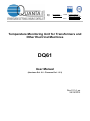
1
http: http: www.quanta.it www.quantasrl.eu e-mail: [email protected] P.E.C.: [email protected] [email protected] [email protected] Temperature Monitoring Unit for Transformers and Other Electrical Machines DQ61 User Manual (Hardware Rel. 2.0 - Firmware Rel. 1.3.3) Rev 01.14_en 28/12/2012 http: http: www.quanta.it www.quantasrl.eu e-mail: [email protected] P.E.C.: [email protected] [email protected] [email protected] 1 2 3 4 General Information _______________________________________________________________ 3 How to use this manual ____________________________________________________________ 3 Identification Data ________________________________________________________________ 4 The DQ61 ______________________________________________________________________ 4 4.1 Terms and conditions of intended use ____________________________________________ 4 4.2 Conditions of use not permitted _________________________________________________ 5 4.3 Technical specifications _______________________________________________________ 6 5 Funzionamento e uso _____________________________________________________________ 7 5.1 Control Panel _______________________________________________________________ 7 5.2 Rear Panel _________________________________________________________________ 8 5.3 Power Supply _______________________________________________________________ 8 5.4 Electrical Connections ________________________________________________________ 8 5.5 Pt100 probes electrical connections ______________________________________________ 9 5.6 Other electrical connections ____________________________________________________ 9 5.7 Relays Functionality __________________________________________________________ 9 5.8 Buzzer features _____________________________________________________________ 10 6 Programming ___________________________________________________________________ 11 6.1 Normal view _______________________________________________________________ 11 6.2 Access to menu ____________________________________________________________ 11 6.2.1 MAX TEMPERATURE RECORD Menu ________________________________________ 11 6.2.2 ALARM SETTING Menu ____________________________________________________ 12 6.2.3 ALARM COUNTERS Menu _________________________________________________ 12 6.2.4 DISPLAY MODE Menu _____________________________________________________ 13 6.2.5 USER Menu _____________________________________________________________ 14 6.2.6 SERVICE Menu __________________________________________________________ 15 6.2.7 INSTRUMENT INFO _______________________________________________________ 17 6.2.8 OUTPUT TEST ___________________________________________________________ 17 7 Remote Control _________________________________________________________________ 18 7.1.1 Communication: Physical Layer ______________________________________________ 18 7.1.2 Communication: Data Layer _________________________________________________ 18 7.1.3 Communication: Application Layer ____________________________________________ 18 7.1.4 Controllable Variables Table _________________________________________________ 18 7.1.5 Data types _______________________________________________________________ 18 7.2 Monitorable and Editable Registers Table ________________________________________ 20 7.2.1 Monitorable and Editable Parameters and Variables ______________________________ 20 7.3 Read-Only Registers Table ___________________________________________________ 21 7.3.1 Read-Only Variables _______________________________________________________ 21 8 Overall Dimensions ______________________________________________________________ 22 9 Troubleshooting _________________________________________________________________ 22 10 User Manual Revision History ______________________________________________________ 22 Via A. Ferrarin, 19-23 • 50145 Firenze (Italy) • Tel.: +39 055 3024555 • Fax: +39 055 317844 P. I.V.A. e Cod. Fisc.: IT 04273220485 REA CCIAA Firenze: n. 0433306 • Registro Imprese n. FI017 -58513 Banche: INTESA-SAN PAOLO - ABI: 06160, CAB: 02848 UNICREDIT – ABI 02008, CAB: 38106 Pag. 2 http: http: www.quanta.it www.quantasrl.eu e-mail: [email protected] P.E.C.: [email protected] [email protected] [email protected] 1 General Information Before performing any work on the device, ensure you have read and fully understood this manual. To ensure safe operation of the product it is necessary that the transport, storage, installation, use, maintenance and disposal practices are in compliance with the instructions in this manual. Each operation on the connections and installation must be performed by qualified and authorized personnel only. The QUANTA S.r.l. cannot be held responsible for any damage to people and/or things if have not been complied with all the instructions in this manual. The product shall be used only for the purpose specified in this manual. Any other use, besides being forbidden, it could pose a risk to health and/or safety of persons and/or property and damage to the equipment. Use only QUANTA S.r.l. original spare parts The use of non-original spare parts will invalidate your warranty, and might pose a risk to health and / or safety of persons and / or property. All rights are reserved. Any form of duplication or distribution of this manual is allowed only under the express written consent of QUANTA S.r.l. 2 How to use this manual This manual should be considered part of the unit, consequently it shall always be available for consultation by the management and maintenance staff. Keep it with care; in case of loss or damage you may request a copy asking your dealer or directly QUANTA S.r.l. quoting the model and serial number of the device, Via A. Ferrarin, 19-23 • 50145 Firenze (Italy) • Tel.: +39 055 3024555 • Fax: +39 055 317844 P. I.V.A. e Cod. Fisc.: IT 04273220485 REA CCIAA Firenze: n. 0433306 • Registro Imprese n. FI017 -58513 Banche: INTESA-SAN PAOLO - ABI: 06160, CAB: 02848 UNICREDIT – ABI 02008, CAB: 38106 Pag. 3 http: http: www.quanta.it www.quantasrl.eu e-mail: [email protected] P.E.C.: [email protected] [email protected] [email protected] 3 Identification Data The identification label is located on the back of the unit. Figure 1 For technical assistance contact QUANTA S.r.l. using references in the footer of this manual. 4 The DQ61 4.1 Terms and conditions of intended use The DQ61 is an electronic control unit, designed to be used to monitor and control the temperature of electrical machines, e.g. medium/high voltage transformers or electrical motors. Since it is not possible to know in advance what are the real application conditions in which the device will be utilized, and given the great variability of the fields of application, it is responsibility of the user to determine the suitability of DQ61 in perform properly the specific application. QUANTA S.r.l. is available to provide the know-how to help customers in the evaluation of the specific suitability of the DQ61. The DQ61 is a device classified under Measure Category III according to EN61010-1, permanently connected. The device must be installed inside an electrical panel and shall be placed in proximity of a switch in order to allow for a swift disconnection from the power supply. The connection cables, including power cables must be secured and protected against the danger of direct contact to the operators. Working on the device shall only be done after power to the panel has been disconnected. Via A. Ferrarin, 19-23 • 50145 Firenze (Italy) • Tel.: +39 055 3024555 • Fax: +39 055 317844 P. I.V.A. e Cod. Fisc.: IT 04273220485 REA CCIAA Firenze: n. 0433306 • Registro Imprese n. FI017 -58513 Banche: INTESA-SAN PAOLO - ABI: 06160, CAB: 02848 UNICREDIT – ABI 02008, CAB: 38106 Pag. 4 http: http: www.quanta.it www.quantasrl.eu e-mail: [email protected] P.E.C.: [email protected] [email protected] [email protected] The device must be used only for the use and in the environmental conditions expressly provided in this manual: Any other use is considered improper and is not permitted. The use in ways and for purposes other than prescribed in this manual raises QUANTA S.r.l. from any liability for damage to persons, animals or property. The device must be used for its intended use, only if in perfect conditions of maintenance. The use is permitted by qualified and trained personnel only, in strict accordance to current safety regulations and standards for the prevention of accidents. In particular, the user should: verify the compliance of the environment in which the equipment is installed and the related arrangements for the proper installation/use. thoroughly understand all the operations necessary for the proper use and the ordinary disposal, and all the general safety instructions and warnings provided in the manual. 4.2 Conditions of use not permitted The use of DQ61 in areas classified in category 20, 21 or 22 and / or 0, 1, 2 according to EU Directive 94/9, called Atex, is expressly prohibited. It is forbidden to use the DQ61 by personnel which is untrained and not aware of the risks related to the use of the device. Via A. Ferrarin, 19-23 • 50145 Firenze (Italy) • Tel.: +39 055 3024555 • Fax: +39 055 317844 P. I.V.A. e Cod. Fisc.: IT 04273220485 REA CCIAA Firenze: n. 0433306 • Registro Imprese n. FI017 -58513 Banche: INTESA-SAN PAOLO - ABI: 06160, CAB: 02848 UNICREDIT – ABI 02008, CAB: 38106 Pag. 5 http: http: www.quanta.it www.quantasrl.eu e-mail: [email protected] P.E.C.: [email protected] [email protected] [email protected] 4.3 Technical specifications Power supply Available inputs Cable lengts compensation External connections Temperature range Accuracy Output alarm relays Output Fan relay Output Fault relay Display Keyboard Alarms signaling Menu language Unit of measure Dimensions Mounting Panel cut-out Building according CE directives Protection against electrical noise Dielectric strength Isolation Frontal protection Ambient operating temperature Ambient operating humitity MTBF Data storage Recorded data Remote control (optional) Universal 90-250Vac 50-60Hz and 16…26Vcc/ac, 7VA N°4 RTD Pt100 – 3 wires 2 Up to 500m (0.5 mm ) Terminals wiring up to AWG 17 for Pt100, up to AWG14 for power and relays -20 … +200°C Better than 0,4°C ±1 digit N°2 SPDT 5A 250V for ALLARM and TRIP N°1 SPDT 5A 250V N°1 SPDT 5A 250V Graphic OLED 2,4” 128x64 pixel Touch capacitive With 4 dedicated LED and text message on display Italian, English, French, Espanol, more on request °C or °F Front 96x96mm; depth 115mm Front panel 90x90mm 2006/95/CEE (Lov Voltage) e 2004/108/CEE (EMC) EN61326-1 2500Vac for 1 minute Better than 100MOhm at 500Vcc ground -other terminals IP40, IP65 optional -20 … +60°C Max 90% no-condensing Better than 100.000 hours More than 10 years Each channel Max temperature; Each alarm number of activactions Optoisolated RS485, MODBUS RTU protocol Self-diagnosis, with error signal on the FAULT relay. Integrated counters (partial and total), for hours of work done. Ability to schedule the regular switch-on of the fans from the service menu. FCD function: ability to set an alarm if the temperature change is too fast (°C/s), from the service menu Ability to disable alarms activation for probes P1 P2 and P3 from the service menu. Ability to disable alarm activation for probe P4 from user menu. Via A. Ferrarin, 19-23 • 50145 Firenze (Italy) • Tel.: +39 055 3024555 • Fax: +39 055 317844 P. I.V.A. e Cod. Fisc.: IT 04273220485 REA CCIAA Firenze: n. 0433306 • Registro Imprese n. FI017 -58513 Banche: INTESA-SAN PAOLO - ABI: 06160, CAB: 02848 UNICREDIT – ABI 02008, CAB: 38106 Pag. 6 http: http: www.quanta.it www.quantasrl.eu e-mail: [email protected] P.E.C.: [email protected] [email protected] [email protected] 5 Funzionamento e uso 5.1 Control Panel 1 3 2 4 7 5 6 Figure 2 Table 1: Panel Layout 1. Display 2. Status Row 3. LED group 4. MENU/ESC Pushbutton 5. + / INCREASE Pushbutton 6. - / DECREASE Pushbutton 7. ENTER/MUTE Pushbutton In normal operation it displays the measured temperatures. During programming it guides the user to setup the parameters. Located at the bottom of the display, it shows the operating condition of the DQ61, alarm conditions particularly. The A1 LED indicates that the cooling fan is ON. The A2 LED indicates an alarm condition. The A3 LED signals the activation of the tripping relay. The A4 LED indicates a fault condition within the unit or on the probes Allows to enter or exit the programming menu. Increase the value of a selected parameter / Displays the menu page or the previous line to the current one. Decreases the value of a selected parameter / Displays the menu page or the following line to the current one. In normal operation: Allows to silence the buzzer. When setting parameters: Confirm the set value and pass to the next parameter. Via A. Ferrarin, 19-23 • 50145 Firenze (Italy) • Tel.: +39 055 3024555 • Fax: +39 055 317844 P. I.V.A. e Cod. Fisc.: IT 04273220485 REA CCIAA Firenze: n. 0433306 • Registro Imprese n. FI017 -58513 Banche: INTESA-SAN PAOLO - ABI: 06160, CAB: 02848 UNICREDIT – ABI 02008, CAB: 38106 Pag. 7 http: http: www.quanta.it www.quantasrl.eu e-mail: [email protected] P.E.C.: [email protected] [email protected] [email protected] 5.2 Rear Panel 1 4 2 3 5 6 Figure 3 Table 2: Terminal Blocks 1. 2. 3. 4. 5. 6. Terminal Reference number 1 2 3 4 5 … 16 17 18 19 20 21 22 23 24 25 26 … 37 Common terminal shield for Pt100 probes Terminals for connection to Pt100 sensors Optional RS485 Serial Communication Power Supply 16-26Vac-dc Power Supply 90-250Vac Relays Terminal Blocks (5A 250V) 5.3 Power Supply On the secondary of large transformers may be present very strong transient disturbances, which might exceed the filters and safeguards built into DQ61 and destroy it; for this reason it is advisable to power it by a transformer 24VAC or 24VDC power supply. If the power is taken directly from the secondary of the transformer to be protected, fit a suitable additional filter. For more information please contact QUANTA S.r.l. 5.4 Electrical Connections For the connection of the measuring sensors (Pt100) it is essential to observe the following rules: They must be placed separate from the power cables. They must be made with shielded twisted conductors. 2 Must have a minimum cross section of 0.5 mm . Must have conductors silver or tin. Via A. Ferrarin, 19-23 • 50145 Firenze (Italy) • Tel.: +39 055 3024555 • Fax: +39 055 317844 P. I.V.A. e Cod. Fisc.: IT 04273220485 REA CCIAA Firenze: n. 0433306 • Registro Imprese n. FI017 -58513 Banche: INTESA-SAN PAOLO - ABI: 06160, CAB: 02848 UNICREDIT – ABI 02008, CAB: 38106 Pag. 8 http: http: www.quanta.it www.quantasrl.eu e-mail: [email protected] P.E.C.: [email protected] [email protected] [email protected] 5.5 Pt100 probes electrical connections 7 Shield Pt100 2 3 5 6 7 4 Red 6 1 Red 5 4 White 3 Rosso 2 Rosso 1 Bianco Schermo Make Pt100 sensors connections as shown in the following diagram, using shielded cables: Pt100 Figure 4 (Figure 4 shows the connection of the single P1 probe). If they are available two-wire Pt100, connect terminals 6 and 7 together. Do the same with the other probes, connecting to terminals 8 to 16 with the screens connected to terminals 2, 3 and 4. The probes P1, P2 and P3 are those which measure the temperature of the three windings in a three-phase transformer, while the probe P4 measures the temperature of the magnetic core. See the diagram below: Pt100 P4 Pt100 P1 Pt100 P2 Pt100 P3 DQ61 Figure 5 5.6 Other electrical connections Connect the low safety voltage power supply to terminals 21 and 22 or connect the mains supply to terminals 23, 24 and 25. WARNING: even if the power supply applied to terminals 21 and 22 is at low safety voltage levels, the ground terminal 24 must be connected, in order to maintain the effectiveness of noise filters and other internal devices. 5.7 Relays Functionality The relays A1 A2 and A3 are normally at rest, while the relay A4 is normally activated, according to the diagrams of example in Figure 6 and Figure 7. The output A1 (signaled by LED FAN) switches when one of the sensors reaches the activation temperature of the fan. Via A. Ferrarin, 19-23 • 50145 Firenze (Italy) • Tel.: +39 055 3024555 • Fax: +39 055 317844 P. I.V.A. e Cod. Fisc.: IT 04273220485 REA CCIAA Firenze: n. 0433306 • Registro Imprese n. FI017 -58513 Banche: INTESA-SAN PAOLO - ABI: 06160, CAB: 02848 UNICREDIT – ABI 02008, CAB: 38106 Pag. 9 http: http: www.quanta.it www.quantasrl.eu e-mail: [email protected] P.E.C.: [email protected] [email protected] [email protected] The relay A2 (signaled by the ALARM LED) switches when the probe reaches the alarm temperature. Enabling this relay can be delayed by setting a time in the user menu. The relay A3 (signaled by LED TRIP) switches when one of the probes reaches a temperature of release. The working mode of this relay can be controlled by the user menu: Standard mode: It is active when you reach the alarm condition and remains active until the condition persists. Latching mode: Keeps the alarm indefinitely, even to the end of the cause of the alarm. Pulse mode: It is activated for a predetermined time and then returns to the rest condition. The relay A4 (indicated by LED FAULT) is always on and going off to signal a DQ61 fault condition or a fault condition in one or more probes. A1 26 27 A2 28 29 30 A3 31 32 33 A4 34 35 36 37 Figure 6 Relay in its rest position; DQ61 ON A1 26 27 A2 28 29 30 A3 31 32 33 A4 34 35 36 37 Figure 7 Fan activated; Fault DQ61 and/or fault probe 5.8 Buzzer features The buzzer is activated at the reach of alarm set-point (ALARM), which also activates the relay A2, and beeps intermittently slow until the end of cause for alarm. The buzzer sounds intermittently fast, when it reaches the release set-point (TRIP) which activates the relay A3. The buzzer sounds a continuous tone to indicate the fault condition of a Pt100 probe. The MUTE key mute the buzzer when alarm is active. In the state of silencing the buzzer wakes up in the presence of new alarm events. The activation of the buzzer on alarm can be inhibited by the service menu.. Type of sound Continuous Intermittent slow Intermittent fast Cause reported One or more probes are faulty Active alarm relay (ALARM) Active tripping relay (TRIP) Via A. Ferrarin, 19-23 • 50145 Firenze (Italy) • Tel.: +39 055 3024555 • Fax: +39 055 317844 P. I.V.A. e Cod. Fisc.: IT 04273220485 REA CCIAA Firenze: n. 0433306 • Registro Imprese n. FI017 -58513 Banche: INTESA-SAN PAOLO - ABI: 06160, CAB: 02848 UNICREDIT – ABI 02008, CAB: 38106 Pag. 10 http: http: www.quanta.it www.quantasrl.eu e-mail: [email protected] P.E.C.: [email protected] [email protected] [email protected] 6 Programming 6.1 Normal view In normal operation, set as the factory default, the display looks like this: At the top, the display shows the four measured temperatures, while the bottom row summarizes the status of the DQ61. 6.2 Access to menu Press the MENU key to access the main menu of programming: With the keys and you place the control on the desired line, with the key you access the submenu. When you are inside a menu, press the MENU button to exit and return to the main display. The row can be reached by pressing the key after the row . If no operations are done on the keyboard for about 30 seconds, DQ61 autonomously back to normal view. 6.2.1 MAX TEMPERATURE RECORD Menu This menu shows the maximum temperatures recorded. Pressing the key twice, you can reset the recorded values. Via A. Ferrarin, 19-23 • 50145 Firenze (Italy) • Tel.: +39 055 3024555 • Fax: +39 055 317844 P. I.V.A. e Cod. Fisc.: IT 04273220485 REA CCIAA Firenze: n. 0433306 • Registro Imprese n. FI017 -58513 Banche: INTESA-SAN PAOLO - ABI: 06160, CAB: 02848 UNICREDIT – ABI 02008, CAB: 38106 Pag. 11 http: http: www.quanta.it www.quantasrl.eu e-mail: [email protected] P.E.C.: [email protected] [email protected] [email protected] 6.2.2 ALARM SETTING Menu This menu shows the temperature set point for fan, alarm and tripping. The settings are common to the probes P1, P2 and P3, while P4 probe has a setting dedicated. By pressing the keys and you place the cursor on the desired set point; the key leads to a submenu that lets you change its value. After changing the value, press the button again to save the change or press the key MENU to return without the change. 6.2.3 ALARM COUNTERS Menu This menu shows how many alarms there were for different set-points. Pressing the key twice, you can reset the counters. Via A. Ferrarin, 19-23 • 50145 Firenze (Italy) • Tel.: +39 055 3024555 • Fax: +39 055 317844 P. I.V.A. e Cod. Fisc.: IT 04273220485 REA CCIAA Firenze: n. 0433306 • Registro Imprese n. FI017 -58513 Banche: INTESA-SAN PAOLO - ABI: 06160, CAB: 02848 UNICREDIT – ABI 02008, CAB: 38106 Pag. 12 http: http: www.quanta.it www.quantasrl.eu e-mail: [email protected] P.E.C.: [email protected] [email protected] [email protected] 6.2.4 DISPLAY MODE Menu This menu allows you to set the screen to normal working mode, as it may be needed. Pressing the keys and you place the cursor on the screen that you want; pressing the key twice, you select and confirm the choice. The choices are as follows: Current temperature of probes. All measured temperatures are displayed simultaneously on the display. Highest temperature. The display shows only the highest temperature measured. Cyclic temperatures. All the temperatures measured are shown in succession, one after the other with an interval of about four seconds. Manual Scan. Acting with the keys and you select the displayed temperature. Via A. Ferrarin, 19-23 • 50145 Firenze (Italy) • Tel.: +39 055 3024555 • Fax: +39 055 317844 P. I.V.A. e Cod. Fisc.: IT 04273220485 REA CCIAA Firenze: n. 0433306 • Registro Imprese n. FI017 -58513 Banche: INTESA-SAN PAOLO - ABI: 06160, CAB: 02848 UNICREDIT – ABI 02008, CAB: 38106 Pag. 13 http: http: www.quanta.it www.quantasrl.eu e-mail: [email protected] P.E.C.: [email protected] [email protected] [email protected] 6.2.5 USER Menu This menu shows the possible settings allowed to the user. Pressing the keys and you can place the cursor on the entry to change; with the key you access a submenu that has the options available. You select the desired option using the buttons and ; use the key to select it and save. . Sets the hysteresis on the alarm temperature between 1 and 20 °C (default 5 °C). For example, if a given alarm threshold is set to 120 °C and the hysteresis at 5 °C, DQ61 signal an alarm when the temperature exceeds 120 °C and will continue to report it until the temperature drops below 115 °C . Sets the time in seconds (between 0 and 120, default 0) for which the alarm condition must persist before an alarm is reported. For example, if this parameter is set to 60 sec., raise in temperature above the thresholds set for periods of less than 60 seconds will not give the alarm. . If set to YES (default NO), once in the conditions for which the alarm TRIP is activated, this alarm (alarm LED on the display and relay contact A3) continues to exist even if the temperature returns to normal until the key is not pressed by an operator. . This parameter allows you to set the time for which the relay contact A3 (TRIP) is activated in case of alarm: if it is set to 0 (default), the relay is activated as long as the alarm condition persists, but if you set a value between 1 and 120 seconds, in case of alarm TRIP the relay will be activated only for that time even if the alarm condition persists. This function, if the value is not 0, takes precedence over latching function. . This feature allows you to disable the alarm activation derived from probe 4. If the probe is connected its temperature is still shown on the display, but if it is absent, no alarms are reported. The alarm condition is signaled disabled on the display in the status line. Via A. Ferrarin, 19-23 • 50145 Firenze (Italy) • Tel.: +39 055 3024555 • Fax: +39 055 317844 P. I.V.A. e Cod. Fisc.: IT 04273220485 REA CCIAA Firenze: n. 0433306 • Registro Imprese n. FI017 -58513 Banche: INTESA-SAN PAOLO - ABI: 06160, CAB: 02848 UNICREDIT – ABI 02008, CAB: 38106 Pag. 14 http: http: www.quanta.it www.quantasrl.eu e-mail: [email protected] P.E.C.: [email protected] [email protected] [email protected] This feature allows you to use the DQ61 to monitor only 3 temperatures without being warned for failure or absence of the fourth probe. . Sets the menu language choosing among ITALIAN, ESPANOL, FRANCAIS, ENGLISH. 6.2.6 SERVICE Menu This menu can only be accessed with a key password (by pressing MENU, MENU, MENU, , MENU,MENU, MENU, ). This menu is reserved for technical assistance. In this menu you can set some special features of the DQ61: Enable FCD feature and choice of rate of temperature rise that generate the alarm . Default 0 °C/s. It may set a value of rate of rise that generates alarm, between 0 and 30 °C/s. Setting the value to 0 exclude the function and the corresponding alarm is disabled. Via A. Ferrarin, 19-23 • 50145 Firenze (Italy) • Tel.: +39 055 3024555 • Fax: +39 055 317844 P. I.V.A. e Cod. Fisc.: IT 04273220485 REA CCIAA Firenze: n. 0433306 • Registro Imprese n. FI017 -58513 Banche: INTESA-SAN PAOLO - ABI: 06160, CAB: 02848 UNICREDIT – ABI 02008, CAB: 38106 Pag. 15 http: http: www.quanta.it www.quantasrl.eu e-mail: [email protected] P.E.C.: [email protected] [email protected] [email protected] Activation interval of the fan (independent of temperature) . Default 0 hours. You can set a value between 0 and 1000h. Setting the value 0, to disable this function: The fan will turn on anyway as a result of exceeding the alarm FAN temperature; setting a value other than 0, for example. 6h, the fan will turn on every 6 hours and will remain on for the time set to the next parameter (P13). FAN ON Time (See parameter P12). . Default 5 minutes. Determines how long the fan stays on if the parameter P12 is different from 0. Probe 1 Enable. . Default YES. Setting the value to NO exclude the alarm probe 1, while remaining visible indication of its temperature on the display. This condition is indicated on the status line with the message “Alarms probe T1 OFF”. The parameters from P14 to P17 allow you to use DQ61 with a number of probes between 1 and 4 without having to worry about the alarms generated by the probes that may be missing. Probe 2 Enable. . Default YES. Setting the value to NO exclude probe 2 alarm, while the temperature on the display remains visible. This condition is indicated on the status line with the message “Alarms probe T2 OFF”. Probe 3 Enable. . Default YES. Setting the value to NO exclude probe 3 alarm, while the temperature on the display remains visible. This condition is indicated on the status line with the message “Alarms probe T3 OFF”. Adjusting the display brightness in the working mode. . Default 240. Adjusting the display brightness in the stand-by mode. . Default 60. The parameters P8 and P19 are connected to each other in the following way: P18 can be set between P19+1 and 255; P19 can be set between 0 and the value of P18-1. ID. MODBUS. . Default 1. (Allowed values: from 1 to 247). If the RS485 MODBUS option is not installed, the value indicated is and will not be editable. RS485 MODBUS Baud rate. . Via A. Ferrarin, 19-23 • 50145 Firenze (Italy) • Tel.: +39 055 3024555 • Fax: +39 055 317844 P. I.V.A. e Cod. Fisc.: IT 04273220485 REA CCIAA Firenze: n. 0433306 • Registro Imprese n. FI017 -58513 Banche: INTESA-SAN PAOLO - ABI: 06160, CAB: 02848 UNICREDIT – ABI 02008, CAB: 38106 Pag. 16 http: http: www.quanta.it www.quantasrl.eu e-mail: [email protected] P.E.C.: Default 19.200. (Allowed values: between 1.200 and 38.400 baud). If the RS485 MODBUS option is not installed, the value indicated is Choice of unit between °C and °F. . Default °C. Buzzer Enable on Alarm [email protected] [email protected] [email protected] and will not be editable. . Default YES. Warning: when the buzzer is disabled it does not sound on activation relay ALARM, TRIP relay and relay FAULT. Default Setting . Default NO. This selection resets the device to factory settings. 6.2.7 INSTRUMENT INFO This menu shows the software revision and hours of work. Pressing twice the key working hours counter. The total counter can not be reset. you can reset the partial 6.2.8 OUTPUT TEST This menu allows you to check the operation of the output relays and LEDs associated with. You select the relay to test using keys and , and then pressing the key switching from off to on and vice versa. Pressing the MENU button the test ends, the relays and the LEDs resume their work status By entering this menu, any alarms are turned off to allow the test and are reactivated at the return of the normal operating condition. Via A. Ferrarin, 19-23 • 50145 Firenze (Italy) • Tel.: +39 055 3024555 • Fax: +39 055 317844 P. I.V.A. e Cod. Fisc.: IT 04273220485 REA CCIAA Firenze: n. 0433306 • Registro Imprese n. FI017 -58513 Banche: INTESA-SAN PAOLO - ABI: 06160, CAB: 02848 UNICREDIT – ABI 02008, CAB: 38106 Pag. 17 http: http: www.quanta.it www.quantasrl.eu e-mail: [email protected] P.E.C.: [email protected] [email protected] [email protected] 7 Remote Control Through the RS485 port (when the corresponding option board is installed) DQ61 can be controlled by an External manager communicating with MODBUS protocol. 7.1.1 Communication: Physical Layer Asynchronous serial communication, half-duplex, 19200bps (default), 8 data bit (LSB first), even parity, 1 stopbit. 7.1.2 Communication: Data Layer Protocol MODBUS Slave over serial line RTU mode. Please refer to MODBUS over serial line specification and implementation guide V1.02 of 20/12/2006 by Modbus.ORG. The address of the MODBUS Slave is the ID MODBUS set from the Service Menu. The Protocol Data Unit (PDU) exchanged with the upper level are associated with the address above, and check for error checking (CRC), forming the Application Data Unit (ADU). 7.1.3 Communication: Application Layer MODBUS Application level second MODBUS Application Protocol Specification V1.1b of 28/12/2006 by Modbus-IDA.ORG for the management of PDUs exchanged with the lower levels. The application layer defines the MODBUS PDU as formed by the following fields: Function Code – Function code indicates the type of action required by the Client to the Server. Data – Field data concerning the operation of control or monitoring required by the Client to the Server. Are supported only the following function codes: Function Code 03 (0x03) 16 (0x10) Description Read Holding Registers Write Multiple Registers As described in detail below, the table of Holding Registers contains not only all the variables that can be monitored and modified (read-write) by the External Manager, but also the variables monitored only (ReadOnly) allocated all together in a separate address space, which in this case shall be extended to the maximum extent permitted by MODBUS (0x0000 to 0xFFFF). Is therefore rejected each write request involving the records Read-Only in that address space. Typical MODBUS requests for diagnostic are not handled over serial lines (08 (0x08) Diagnostics, 11 (0x0B) Get Comm Event Counter and 12 (0x0C) Get Comm Event Log). 7.1.4 Controllable Variables Table The data of all controllable variables are mapped into a table of 16-bit registers, depending on the model MODBUS data representation. 7.1.5 Data types The data is divided into the following types: BOOL – binary value 0 or 1 Via A. Ferrarin, 19-23 • 50145 Firenze (Italy) • Tel.: +39 055 3024555 • Fax: +39 055 317844 P. I.V.A. e Cod. Fisc.: IT 04273220485 REA CCIAA Firenze: n. 0433306 • Registro Imprese n. FI017 -58513 Banche: INTESA-SAN PAOLO - ABI: 06160, CAB: 02848 UNICREDIT – ABI 02008, CAB: 38106 Pag. 18 http: http: www.quanta.it www.quantasrl.eu e-mail: [email protected] P.E.C.: [email protected] [email protected] [email protected] CHAR – alphanumeric character (0 ÷ 255) BYTE – 8-bit positive integer (0 ÷ 255) WORD – 16-bit positive integer (0 ÷ 65535) BITMAP – 16-bit words corresponding to 16 flags in order from 0 to 15 (for each bit logic is: 0 = off, 1 = on) INT – 16-bit signed integer (-32768 ÷ 32767) DWORD – 32-bit positive integer (0 ÷ 4294967295) LONG – 32-bit signed integer (-2147483648 ÷ 2147483647) FLOAT – IEEE 754 single-precision floating point number (±1.175494351E–38 ÷ ± 3.402823466E+38) For the type CHAR and BYTE, the 16-bit register that contains it has the high byte set as zero, unless it is an array. For type DWORD, LONG and FLOAT the two 16-bit registers that represent the value in the table are sorted according to the scheme Big-Endian (Motorola): The first register contains the high word, the second register contains the low word. For arrays of CHAR and BYTE, each 16-bit register employed from the array contains two elements: The k-th element in the low byte and the (k +1)-th element in the high byte, with k = 0.1, 2, ... index of characters in the array. The element of null value (0x00) is taken as a string terminator in arrays of CHAR. The notation "[n]" indicates the size of an array of n elements of a certain type. Via A. Ferrarin, 19-23 • 50145 Firenze (Italy) • Tel.: +39 055 3024555 • Fax: +39 055 317844 P. I.V.A. e Cod. Fisc.: IT 04273220485 REA CCIAA Firenze: n. 0433306 • Registro Imprese n. FI017 -58513 Banche: INTESA-SAN PAOLO - ABI: 06160, CAB: 02848 UNICREDIT – ABI 02008, CAB: 38106 Pag. 19 http: http: www.quanta.it www.quantasrl.eu e-mail: [email protected] P.E.C.: [email protected] [email protected] [email protected] 7.2 Monitorable and Editable Registers Table 7.2.1 Monitorable and Editable Parameters and Variables Address 0x0000 Type BITMAP Description Bitmap configuration flag: Bit0. Default configuration Bit1. TRIP latch Enabled Bit2. Probe T1 Enabled Bit3. Probe T2 Enabled Bit4. Probe T3 Enabled Bit5. Probe T4 Enabled Bit6. Unit of Measure = °F Bit7. Buzzer on Alarm Enabled Bit8. Bit9. Bit10. Bit11. Bit12. Bit13. Bit14. Bit15. 0x0001 0x0002 0x0003 0x0004 0x0005 0x0006 0x0007 0x0008 0x0009 0x000A 0x000B 0x000C 0x000D 0x000E 0x000F 0x0010 0x0011 0x0012 0x0013 0x0014 0x0015 0x0016 INT INT INT INT INT INT BYTE BYTE BYTE BYTE WORD BYTE DWORD FAN Probes 1/2/3 (°C o °F) Set-Point FAN Probe 4 (°C o °F) Set-Point ALARM Probes 1/2/3 (°C o °F) Set-Point ALARM Probe 4 (°C o °F) Set-Point TRIP Probes 1/2/3 (°C o °F) Set-Point TRIP Probe 4 (°C o °F) Set-Point Hysteresis (°C o °F) FCD (°C/s or °F/s) Set-Point Alarm Delay (s) TRIP Pulse Duration (s) Auto Ventilation Period (h) Auto Ventilation Time (min) Partial Working Hours (Reset only) INT INT INT INT WORD WORD WORD WORD Max Temperature T1 (°C o °F) (Reset only) Max Temperature T2 (°C o °F) (Reset only) Max Temperature T3 (°C o °F) (Reset only) Max Temperature T4 (°C o °F) (Reset only) Number of Activation of Relays FAN (Reset only) Number of Activation of Relays ALARM (Reset only) Number of Activation of Relays TRIP (Reset only) Number of Activation of Relays FAULT (Reset only) Via A. Ferrarin, 19-23 • 50145 Firenze (Italy) • Tel.: +39 055 3024555 • Fax: +39 055 317844 P. I.V.A. e Cod. Fisc.: IT 04273220485 REA CCIAA Firenze: n. 0433306 • Registro Imprese n. FI017 -58513 Banche: INTESA-SAN PAOLO - ABI: 06160, CAB: 02848 UNICREDIT – ABI 02008, CAB: 38106 Pag. 20 http: http: www.quanta.it www.quantasrl.eu e-mail: [email protected] P.E.C.: [email protected] [email protected] [email protected] 7.3 Read-Only Registers Table 7.3.1 Read-Only Variables Address 0x8000 Type WORD 0x8001 0x8002 0x8003 0x8004 0x8005 INT INT INT INT BITMAP 0x8006 BITMAP 0x8007 0x8008 DWORD Description Firmware Release: Bit15÷11 – Version number Bit10÷6 – Revision number Bit5÷0 – Build number Temperature T1 (°C o °F) Temperature T2 (°C o °F) Temperature T3 (°C o °F) Temperature T4 (°C o °F) Bitmap #1 Alarms Status: Bit0. Default Configuration Bit1. Active FAN (T1) Bit2. Active FAN (T2) Bit3. Active FAN (T3) Bit4. Active FAN (T4) Bit5. ALARM (T1) Bit6. ALARM (T2) Bit7. ALARM (T3) Bit8. ALARM (T4) Bit9. TRIP (T1) Bit10. TRIP (T2) Bit11. TRIP (T3) Bit12. TRIP (T4) Bit13. Probe FAULT (T1) Bit14. Probe FAULT (T2) Bit15. Probe FAULT (T3) Bitmap #2 Alarms Status: Bit0. Probe FAULT (T4) Bit1. FCD: Temperature Rapid Rise (T1) Bit2. FCD: Temperature Rapid Rise (T2) Bit3. FCD: Temperature Rapid Rise (T3) Bit4. FCD: Temperature Rapid Rise (T4) Bit5. Probe T1 OFF Bit6. Probe T2 OFF Bit7. Probe T3 OFF Bit8. Probe T4 OFF Bit9. Bit10. Bit11. Bit12. Bit13. Bit14. Bit15 Total Working Hours Via A. Ferrarin, 19-23 • 50145 Firenze (Italy) • Tel.: +39 055 3024555 • Fax: +39 055 317844 P. I.V.A. e Cod. Fisc.: IT 04273220485 REA CCIAA Firenze: n. 0433306 • Registro Imprese n. FI017 -58513 Banche: INTESA-SAN PAOLO - ABI: 06160, CAB: 02848 UNICREDIT – ABI 02008, CAB: 38106 Pag. 21 http: http: www.quanta.it www.quantasrl.eu e-mail: [email protected] P.E.C.: [email protected] [email protected] [email protected] 8 Overall Dimensions 96 90 96 90 9 99,6 115 Figure 8 9 Troubleshooting In the event of unexpected behavior, before concluding that the unit is faulty, check the following list: Symptom The DQ61 not turn on The display indicates “---“ instead of the temperature of a probe Cause and / or remedies Make sure there is voltage at the power supply terminals. Make sure the power connector is properly inserted in its place. Ensure that the wires are securely clamped in the terminals. The indicated probe is open or shorted. Replace the probe. 10 User Manual Revision History 1.14 28 Dicembre 2012 English language first release Via A. Ferrarin, 19-23 • 50145 Firenze (Italy) • Tel.: +39 055 3024555 • Fax: +39 055 317844 P. I.V.A. e Cod. Fisc.: IT 04273220485 REA CCIAA Firenze: n. 0433306 • Registro Imprese n. FI017 -58513 Banche: INTESA-SAN PAOLO - ABI: 06160, CAB: 02848 UNICREDIT – ABI 02008, CAB: 38106 Pag. 22