1
PPA
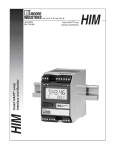
Phase Angle Transducer
USER’S MANUAL
February 1992
© 1992 by Moore Industries-International, Inc.
No. 311-701-00 A
Table of Contents
Introduction
1
Description
1
Calibration
4
Installation
12
Operation
13
Maintenance
13
PPA
Page 1
Introduction
levels. Both of these adjustments are accessible at
the front panel of the PPA.
Moore Industries’ Phase Angle Transducer (PPA)
measures the phase angle of single- or three-phase
ac power circuits by monitoring two voltage or a
combination of voltage and current inputs and
produces a proportional process variable current
output.
A single internal jumper is provided for field-configuration of the unit for single- or three-phase input
operation. Units equipped with the MG Option have
additional jumpers for configuring the unit for singleor three-phase operation.
This manual contains descriptive, calibration, and
installation information for the PPA. Notes and
Warnings are provided in this manual to help the
user avoid minor inconveniences (Notes) and
personal injury (Warnings) while calibrating or
installing the PPA.
An optional liquid crystal display (LCD), which
provides readouts of the phase angle of the input in
degrees, is available for the PPA. Other useful
options are also available, and some of the more
popular are described in the following subsection
(Options).
Description
Table 1 contains the operational and performance
specifications for the PPA. Table 2 is a supplemental table containing the PPA’s overload current
ratings.
The PPA accepts two voltage inputs or a voltage and
a current input and produces a proportional current
output that is linear with the phase angle of the
inputs. The PPA will drive the output to zero percent
should the voltage input (Va input for dual voltage
inputs) be lost or removed while the current or the
other voltage input is still applied. If the current input
or both voltage inputs are removed from the unit, the
output will be either plus or minus maximum — no
certainty as to which, but it will be one extreme or the
other.
The input, output, and operating power requirements
for the PPA are all factory-configured to user specifications, selected from the available settings listed in
table 1.
The PPA is packaged in an aluminum housing that
can be either surface mounted (SM Housing) or DINrail mounted (DM Housing). Electrical connections
are made to terminal strips located on the front panel
of each unit. An optional safety cover is available for
each terminal strip. This optional safety cover is
made of a non-conductive material and is easily
removed to access the terminals.
Every PPA is equipped with zero and span adjustments for setting the zero- and 100-percent output
Options
The PPA is available with some user-friendly and
application-specific options. The following paragraphs contain brief descriptions of some of the more
popular options for the PPA. For information on
availability of options not described here, contact
your local sales representative or Moore Industries
directly.
DSP Option — Provides a 3.5-digit, front-panel LCD
that displays the input phase angle in degrees.
MG Option — Provides a motor or generator contact-closure (relay) output and front-panel LED’s to
indicate the direction of current flow. This option
requires one voltage input and one current input; this
option will not work with two voltage inputs.
RO Option — Provides a reverse output that is
proportional to the input. In cases where the input
would produce a zero-percent output, with this option
the output would be the full-scale (100-percent)
output rating of the unit. Where the output would
normally be 100-percent, it would be zero-percent
with this option.
PPA
Page 2
Table 1. PPA Operational and Performance Specifications
Characteristic
Input
Specifications
Factory-configured.
Voltage-Voltage or Voltage-Current
Voltages: 69 Vac (50-90 Vac)
Current:1 A (0.05-1 A)
120 Vac (85-150 Vac)
2 A (0.1-2 A)
240 Vac (170-300 Vac)
5 A (0.2-5 A)
460 Vac (300-575 Vac)
10 A (0.3-10 A)
600 Vac (425-750 Vac)
25 A (1-25 A)
(Single- or three-phase operation is user-configurable.)
Output
Factory-configured.
–1 to 1 mA (–1 mA = full lead, 0 mA = 0 deg., 1 mA = full lag)
0-1 mA, bidirectional (0 mA = full lead, 0.5 mA = 0 deg., 1 mA = full lag)
4-20 mA (4 mA = 0 deg., 20 mA = full lag)
4-20 mA , bidirectional (4 mA = full lead, 12 mA = 0 deg., 20 mA = full lag)
4-20 mA, lead (20 mA = full lead, 4 mA = 0 deg.)
Power
Factory-configured.
Self-powered (from voltage input)
120 or 240 Vac (external power)
12-42 Vdc (loop-powered; 4-20 mA output units ONLY)
Controls
Adjustments: Two front-panel, multiturn potentiometers
Zero: Adjusts zero-percent output to within ±2% of span
Span: Adjusts 100-percent output to within ±10% of span
Jumpers: A single internal jumper for configuring unit for single- or threephase operation; with MG Option, two additional jumpers for this same
setting
Indicators
LCD: With DSP Option; 3.5-digit liquid crystal display; displays the input
phase angle in degrees from –180.0° to 180.0°
LED: With MG Option; two red LED’s indicate if the input represents a
motor or a generator
Performance
Accuracy: ±0.5°, maximum; or ±0.01 power factor
Stability: ±0.1% of reading per year
Dielectric Test: 2000 Vrms for 1 min between input-output-power-case;
1500 Vrms with any RSxxx Option
Ripple: 1% peak of full-scale at maximum span and load
Response: 400 msec to 99% of output
Overload Voltage: 1.5 times nominal input voltage
Overload Current: SEE TABLE 2
Ambient Temperature Effect: ±0.01% of span per °C
Environmental
Ratings
Weight
Ambient Operating Temperature: –40 to 80 °C (–40 to 176 °F)
Relative Humitity (operating): 0 to 95%, non-condensing
0.85 kg (1 lb, 14 oz)
NOTE: Refer to the Installation Section for the PPA’s outline dimensions.
PPA
Page 3
Table 2. Overload Current Ratings (from table 1)
Input
Continuous
10 sec/hr
3 sec/hr
1 sec/hr
0.5 sec/hr
1
10
15
20
50
100
2
15
25
50
100
250
5
20
50
100
250
400
10
20
50
100
250
400
30
75
100
250
400
25
NOTE: All values are rated in amps (A).
RS232C & RS485 Options — Provides a frontpanel, 9-pin, RS-232 connector for output to computers for communications in RS-232C or RS-485
protocols. Each has a different internal circuit.
TJ Option — Provides a front-panel test jack for
monitoring the output. Does not interrupt output
loop.
Serial/Model Number. A historical record is maintained on every PPA sold and serviced by Moore
Industries. The historical information is keyed to the
units serial number. To obtain historical information,
or for technical assistance by phone, you must
provide both the serial number and model number of
the unit in question to a Moore Industries’ representative.
The serial and model numbers for the PPA are
located on a label that is affixed to the right side
panel of the unit.
The following example identifies the significance of
each field of the PPA model number:
EXAMPLE
PPA / 120AC,1A,1P / 4-20MA / 90 / -120AC [SM]
Unit Type
Input
Output
Power Factor/
Phase Angle
Option(s)
Housing
PPA
Page 4
Calibration
Every PPA is calibrated and tested at the factory
prior to shipment. Before placing a PPA into service,
we recommend that you first bench check each unit,
if possible, and then field calibrate each unit, if
necessary. By performing a bench check, you can
verify that each unit is configured properly for the
intended application and determine if adjustments to
the output are required.
The factory-calibration is performed using highly
accurate test equipment to verify that each PPA
meets customer specifications. This equipment may
be unavailable at some facilities. The Calibration
Setup subsection describes the calibration equipment required.
PPA Controls
The PPA has two types of controls; the Zero and
Span potentiometers (pots), and the single- or threephase jumper. Units factory-configured with the MG
Option are equipped with two additional jumpers,
which are also used to configure the unit for singleor three-phase input operation.
Zero and Span Adjustments. The zero and span
adjustments are multiturn pots that are located on
the front panel of the PPA, and are labeled “ZERO”
and “SPAN”.
The ZERO pot is used to set the zero-percent output
to within ±2% of span. The SPAN pot is used to set
the full-scale (100-percent) output (1 or 20 mA), to
within ±10% of span.
Each of these pots is equipped with a slip-clutch at
each end of the wiper blade travel. If either pot is
turned to its extreme, in either direction, you will feel
a slipping sensation and in some cases you will hear
a clicking sound as the potentiometer shaft is rotated. Turning either pot clockwise increases the
value of the respective output. Turning them
counterclockwise decreases the respective output
value.
Jumpers. The basic PPA has one jumper whose
position is user-selectable for single- or three-phase
input operation (not on voltage-voltage input units).
This jumper is located on PC1. To access it, the unit
must be disassembled. Figure 1 illustrates the
disassembly required to access this jumper. Figure
2 shows the jumper location and positioning options
for selecting single- of three-phase operation.
Units equipped with the MG Option have two additional jumpers. These jumpers are also located on
PC1, and are also used to configure the PPA for
single- or three-phase operation. Figure 2 shows the
jumper setting options for units with the MG Option.
PPA Indicators
The basic PPA has no visual indicators, but the DSP
Option provides an LCD. This LCD is a 3.5-digit
display (with fixed decimal point, xxx.x) that provides
readouts of the phase angle of the inputs with
readings ranging from –180.0 to 180.0. (For values
greater than zero (0.0), no positive sign (+) is displayed.)
Units configured with the MG Option have two red
LED’s to indicate that the input is either from a motor
or a generator. To use the MG Option, the inputs
must be a combination of a voltage and a current
source. Based on the phase relationship of the
inputs, the PPA will indicate if the input is representative of a motor or a generator. If the phase angle
between the voltage and current inputs is greater
than ±90°, its a generator; if less than ±90°, its a
motor.
PPA
Page 5
PC1
FRONT
PANEL
BOTTOM OF
UNIT
Figure 1. PPA Disassembly – Accessing PC1
PPA
Page 6
NO
MG OPTION
WITH
MG OPTION
JC
JD
JE
JD
THREE
PHASE
SINGLE
PHASE
JF
JE
SINGLE
PHASE
WITH
MG OPTION
THREE
PHASE
JB
U1
JA
U2
U3
SINGLE
PHASE
THREE
PHASE
U4
U5
BOTTOM
OF PC1
U6
K1
U11
Figure 2. PC1, Jumper Locations and Settings
PPA
Page 7
Calibration Setup
calculate other specific readings [I (current) = E
(volts) ÷ R (resistance)].
The equipment used to factory-calibrate the PPA
may be unavailable at some facilities. But, to
perform the field calibration procedure properly, you
must use the equipment as describes in this section.
Table 3 lists the calibration equipment required to
bench check and calibrate the PPA.
Output Reading Conversions. Two load resistors
are listed in table 4; a 250ý and a 5000ý. Units
configured for a 4-20 mA output require the 250ý
resistor. Units configured for a 0-1 mA or –1 to 1 mA
output require the 5 ký resistor.
Readings taken with the voltmeter during calibration
will be in volts when read across one of these load
resistors. A 4-20 mA output loaded with a 250ý
resistor will read 1-5 volts (1 V = 4 mA; 5 V = 20 mA).
A 0-1 mA output loaded with a 5 ký resistor will read
0-5 volts (0 V = 0 mA; 5 V= 1 mA). A –1 to 1 mA
output loaded with a 5 ký resistor will read –5 to 5
volts (–5 V = –1 mA; 5 V = 1 mA). Use Ohms Law to
Adjusting Bidirectional Units. When adjusting the
zero-percent output for bidirectional units, the midpoint of the output range is the set point for the zero
adjustment. Table 4 contains the mid-point (0
degrees) output settings by unit output configuration
(refer to the unit’s model number for its output
configuration). For other output configurations, the
ZERO pot is used to set the output to the minimum
output value shown in the unit’s model number. The
SPAN pot is still used to set the full-scale output to
the maximum output rating of the unit.
With bidirectional outputs, the total span of the output
signal is divided equally into two portions; leading
and lagging. For example, from zero degrees to full
lag of a 4-20 mA bidirectional unit, the span is 8 mA
instead of the total span of 16 mA. This is important
to note when converting current output ratings to
voltage for output readings, and for determining the
output percentage that corresponds to the power
factor settings required to adjust the full-scale output,
as discussed in the next paragraph.
Table 3. PPA Calibration Equipment
Equipment
Specification
Input Source
ROTEK, Power/Energy Calibrator 811A
DC Voltmeter
Accuracy of 0.005%, or better
Load Resistor
Ohmmeter
Voltage Adaptor
250ý resistor for 4-20 mA outputs; 5 ký for 0-1 or -1 to 1 mA outputs;
0.01% tolerance
FOR UNITS WITH MG OPTION ONLY
FOR VOLTAGE-VOLTAGE UNITS ONLY; Moore Industries’ Voltage
Adapator module; to convert a current output from the ROTEK to a
voltage input to the PPA
Screwdriver
Slotted-tip, head width no greater than 2.54 mm (0.1 in)
Technicians
Tweezers
For setting jumpers, when required; needle-nose pliers may also be
used
PPA
Page 8
Setting Jumpers. To set jumpers, the PPA must be
disassembled. Figure 1 illustrates the disassembly
required to access the jumper(s) on PC1. Figure 2
shows the jumper location(s) and setting options.
Units configured for voltage-voltage inputs do not
require any jumper settings; therefore, disassembly
of these units is not necessary. The PPA does not
need to be opened to check or adjust the zero or
span setting. For personal safety and ease of
handling, re-assemble the PPA after jumper settings
are complete or before making electrical connections
to the unit.
Table 4. Mid-point Output Settings
Output
(in mA)
Full
Lead
Mid-point
(0°)
Full
Lag
–1 to 1
–1
0
1
0-1 Bi.
0
0.5
1
4-20 Bi.
4
12
20
4-20
—
4
20
4-20 Lead
20
4
—
NOTE: The calibration procedure calls for a
load resistor and voltmeter to take
output readings. Refer to the
Calibration Setup subsection for
current-to-voltage conversion
information.
Figure 3 is a calibration hookup for a PPA configured
for one voltage and one current input, with the MG
Option.
Figure 4 is a calibration hookup for loop-powered
units. These units require a 4-20 mA process loop to
operate properly.
Figure 5 is a calibration hookup for a PPA configured
for two voltage inputs. (The MG Option is not
available for units with two voltage inputs.)
Power Factor Settings. When making the span
adjustment, the POWER FACTOR setting of the
ROTEK 811A varies depending on the power factor
or phase angle configuration of the PPA being
calibrated. Table 5 contains the power factor setting
for the ROTEK 811A and the percentage of full-scale
output to be achieved when making the span adjustment for specific unit configurations.
Table 5. Full-scale Adjustment Power Factor Settings
PPA Configuration
Power
Phase
Factor
Angle
ROTEK 811A
Power Factor
Setting
Target Full-scale
Output Percentage
(%)
0
0.1
93.6
0.3
0.3
100
0.5
0.5
100
0.7
0.7
100
30
0.9
86.14
45
0.7
101.3
60
0.5
100
90
0.1
84.26
180
0
50
PPA
Page 9
ROTEK 811A
DC
VOLTMETER
VOLTAGE
–
–
+
CURRENT
–
+
+
LR
–
+
V
V
I
I
OUTPUT
PPA
NC
COM
NO
AC
POWER
INPUT
OHMETER
NOTE:
LR = 250 for 4-20 mA output or 5 k
for 0-1 and -1 to 1 mA outputs.
Figure 3. PPA Calibration Setup – Voltage-Current Input with MG Option
DC
VOLTMETER
–
+
ROTEK 811A
VOLTAGE
–
12-42
VDC
POWER
SOURCE
CURRENT
+
–
+
LR
+
–
–
+
V
V
I
I
OUTPUT
PPA
NOTE:
LR = 250 for 4-20 mA output or 5 k
for 0-1 and -1 to 1 mA outputs.
Figure 4. PPA Calibration Setup – Loop-powered Units
PPA
Page 10
ROTEK 811A
DC
VOLTMETER
–
VOLTAGE
–
+
CURRENT
+
–
+
–
–
+
LR
–
+
+
Va
Va
Vb
MII
VOLTAGE
ADAPTER
Vb
OUTPUT
PPA
AC
POWER
INPUT
NOTE: LR = 250 for 4-20 mA output or 5 k
for 0-1 and -1 to 1 mA outputs.
Figure 5. PPA Calibration Setup – Voltage-Voltage Input Units
Calibration Procedure
Zero and Span Adjustment
Before beginning this procedure, check the units’s
model number for the configuration of the PPA to be
calibrated. This information will be needed throughout this procedure for calibration setup, equipment
settings, and output readings.
1. For voltage-current input units, disassemble PPA
(see figure 1) and set internal jumper(s) for
single-phase input (including three-phase units)
as shown in figure 2. Slide electronics back into
housing after jumper(s) is/are set.
WARNING
Extremely high voltages are present at
the current input terminals (I, •I) when
either of the input wires is disconnected
and current is still being applied.
Ensure that the current input wires from
the ROTEK Model 811A to the PPA
terminals remain securely connected at
all times while current is supplied to the
PPA.
2. Connect PPA to calibration equipment as shown
in figure 3, 4, or 5, as appropriate.
3. With ROTEK 811A in STANDBY mode, set it for
voltage and current input settings as required for
PPA’s configuration.
4. Apply external power to PPA, and depress
OPERATE button on ROTEK 811A to apply input
to PPA.
PPA
Page 11
5. Set ROTEK 811A POWER FACTOR control to 1.
Select lag by depressing LAG push button.
6. Adjust ZERO pot for a zero-percent output
reading. Refer to table 4 for bidirectional output
units; use zero degree (0°) values converted to
volts.
14. Span adjustment is not required.
15. For three-phase input units, field calibration is
complete. Turn ROTEK 811A off, or set to
STANDBY, before disconnecting equipment.
Checking the MG Option
7. Set ROTEK 811A POWER FACTOR control to
appropriate setting for full-scale adjustment per
unit configuration. Refer to table 5.
8. Adjust SPAN pot for a percentage output as
listed in table 5 for power factor setting used in
step 7. (NOTE: Not all settings are 100%.)
NOTE
Complete the Zero and Span Adjustment
procedure described previously before
preceding with this check.
1. Remove input energy from PPA and set jumpers
for single-phase input as shown in figure 2.
9. For single-phase input units, repeat steps 5
through 8 until zero and full-scale outputs are
stable.
2. Set ROTEK 811A POWER FACTOR control to
any setting except 0.
10. For any single-phase input and voltage-voltage
input units, field calibration is complete. Turn
ROTEK 811A off, or set to STANDBY, before
disconnecting equipment.
3. Connect an ohmmeter between terminals 7 and
8 at front panel of PPA. Verify a short exists
across these normally-closed contacts and that
only MOTOR LED is illuminated.
NOTE
For MG Option check, refer to the
following procedure before disconnecting
equipment.
For three-phase input units, continue with
step 11.
11. Turn ROTEK 811A off, or set to STANDBY, and
set internal jumper(s) for three-phase input as
shown in figures 2.
12. Set ROTEK 811A POWER FACTOR control to 0.
Ensure LAG push button is still depressed.
13. Monitor output reading and adjust ZERO pot, as
necessary for a zero-percent output reading.
Refer to table 4 for bidirectional output units; use
zero degree values converted to volts.
4. Reverse voltage polarity to PPA at ROTEK 811A
voltage output connectors.
5. Verify that MOTOR LED extinguishes and only
GENERATOR LED illuminates.
6. Connect an ohmmeter between terminals 7 and
8 and verify that these normally-closed contacts
an open reading (Infinite) on ohmmeter.
7. Connect ohmmeter between terminals 8 and 9
and verify that a shorted condition exists across
these relay contacts.
8. Reverse voltage input polarity again and note
relay and LED states return to origin condition.
9. Turn ROTEK 811A off, or set to STANDBY,
before disconnecting equipment.
PPA
Page 12
Installation
Installation of the PPA is divided into two phases;
physical mounting and completing the electrical
connections. Generally, it is less cumbersome to
physically mount a unit before completing the
electrical connections.
Mounting the PPA
The PPA is available in two aluminum housing
styles; a surface-mount (SM) a the DIN-rail mount
(DM).
Surface-mount units may be mounted on any sturdy,
flat surface. SM units have four keyhole cutouts (two
on each side) of the rear mounting plate for easy
mounting and removal.
DM units are designed to mount directly on standard
DIN rails. These units are equipped with two mounting clips on the rear panel that are used to attach the
unit to the rail. To complete the mounting of DM
housed units, place the upper portion of the rearpanel clip under the upper lip of the DIN rail, then,
pivot the unit down and back until the lower portion of
the clip snaps on to the lower portion of the DIN rail.
For best performance, mount the PPA in an area free
of excessive dust, moisture, and corrosive elements.
Figure 6 contains the outline dimensions for the PPA.
Making the Electrical Connections
Every PPA is equipped with the same number of
terminals. The configuration of the unit determines
which terminals will be used. For example, if a unit is
loop-powered, none of the lower terminals are used
on a basic PPA.
133.4 mm
(5.25 in)
120.7 mm
(4.75 in)
104.1 mm
(4.10 in)
(SEE NOTE)
1
2
OUTPUT
3
V
4
V
33 mm
(1.30 in)
5
I
6
I
PPA
PHASE ANGLE
ZERO
38.1 mm
(1.50 in)
104.2 mm
(4.10 in)
TRANSDUCER
SPAN
EXT.
POWER
7
8
9
10
NOTE:
Figure 6. PPA Outline Dimensions
11
12
DIN rail-mount units have overall width of 104.1 mm (4.1
PPA
Page 13
Each terminal has a slotted-head screw that is used
to make individual wiring connections.
PPA’s configured with the MG Option provide a
contact-closure output at terminals 7, 8, and 9.
Terminals 7 and 8 are normally-closed (NC) and
terminals 8 and 9 are normally-open (NO) — terminal
8 is common. These relay contacts can be used for
external motor/generator indications or some other
suitable contact-closure application. The MG Option
relay is rated for 300 Vac, 6 A.
Figure 7 illustrates a typical hookup of a single-phase
input, with MG Option. Figure 8 illustrates a typical
hookup of a three-phase input, with MG Option.
Figure 9 and 10 illustrates loop-powered hookups for
single- and three-phase inputs, respectively. Looppowered units require a 4-20 mA loop.
Figure 11 illustrates a hookup for a PPA configured
for two voltage inputs.
Operation
The basic PPA has no indicators. Unless the unit is
configured with the DSP Option (an LCD) or the MG
Option (two red LED’s), the PPA will operate unattended once installed.
PPA’s equipped with an LCD provide a readout of
the phase angle of the inputs in degrees. These
readouts range from –180.0° to (+)180.0°.
Units configured with the MG Option have two LED’s
to indicate that the input is either from a motor or a
generator, based on the phase angle of the inputs.
These LED’s are on the front panel adjacent to the
relay contact terminals. The MG Option relay
changes state in conjunction with the LED’s. The
relay action can be used for external indications.
Maintenance
The PPA is built with highly reliable components,
which allows it to operate unattended for extended
periods of time. Because of this high reliability, field
maintenance is limited to ensuring that wire terminals
on the unit are clean and tight.
We recommend that the PPA be inspected for
mounting security, terminal corrosion, and general
cleanliness at least once every six months.
For technical assistance, or for more information
about the PPA, contact Moore Industries’ Customer
Service Department by dialing 1-800-999-2900.
PPA
Page 14
LINE
OUTPUT
+
–
1
2
3
V
OUTPUT
4
V
5
I
6
I
EXT.
POWER
7
8
9
10
11
12
NC COM NO
RELAY CONTACTS
OF MG OPTION
LOAD
NOTE:
AC
POWER
INPUT
Use ac power input only if unit is configured with
120AC or 240AC Option.
Figure 7. Installation Hookup for Single-phase Inputs
PPA
Page 15
LINE
A
B
C
OUTPUT
+
–
–1
+2
3
V
OUTPUT
4
V
5
6
I
I
EXT.
POWER
7
8
9
10
11
12
NC COM NO
A
B
C
RELAY CONTACTS
OF MG OPTION
LOAD
NOTE:
AC
POWER
INPUT
Use ac power input only if unit is configured with
120AC or 240AC Option.
Figure 8. Installation Hookup for Three-phase Inputs
PPA
Page 16
LINE
12-42 VDC
POWER SOURCE
CURRENT
DRIVEN
DEVICE
–
+
–
+
4-20 mA
–1
+2
3
OUTPUT
V
4
V
5
6
I
I
EXT.
POWER
7
8
9
10
11
12
LOAD
Figure 9. Installation Hookup for Single-phase Inputs – Loop-powered
PPA
Page 17
LINE
A
B
C
12-42 VDC
POWER SOURCE
CURRENT
DRIVEN
DEVICE
–
+
–
+
4-20 mA
–1
+2
3
V
OUTPUT
4
V
5
6
I
I
EXT.
POWER
7
A
B
8
9
10
11
12
C
LOAD
Figure 10. Installation Hookup for Three-phase Inputs – Loop-powered
PPA
Page 18
A
LINE
B
C
OUTPUT
+
–
–1
+2
3
OUTPUT
Va
4
Va
5
6
Vb
Vb
EXT.
POWER
7
A
B
8
9
10
12
AC
POWER
INPUT
C
LOAD
NOTE:
11
Use ac power input only if unit is configured with
120AC or 240AC Option.
Figure 11. Installation Hookup for Voltage-Voltage Inputs
NOTES
Declaration of Conformity
EMC Directive 89/336/EEC
Manufacturer’s Name:
Manufacturer’s Address:
Moore Industries-International, Inc.
16650 Schoenborn Street
North Hills, CA 91343-6196
USA
Declares that the product(s):
Product Name:
PPA
MODEL
Model Number(s):
PPA
/
INPUT
*
/
OUTPUT
/
*
POWER
*
/
OPTIONS
/
HOUSING
*-CE
*
*Indicates any input, output, power, option and housing as stated in the product data sheet.
Conforms to the following EMC specifications:
EN50081-2, 1993, Generic Emissions Standard, Industrial Environment.
EN50082-2, 1995, Generic Immunity Standard, Industrial Environment.
EN61010-1, 1995, Safety requirements for electrical equipment for measurement and control use.
Supplemental Information:
None.
October 1, 1997
Date
______________________________
Fred Adt
Quality Assurance Director
_____________________________________
Robert Stockham
Moore Industries-International, Inc.
European Contact: Your Local Moore Industries Sales and Service Office
RETURN PROCEDURES
To return equipment to Moore Industries for repair, follow these four steps:
1. Call Moore Industries and request a Returned Material Authorization (RMA) number.
Warranty Repair –
If you are unsure if your unit is still under warranty, we can use the unit’s serial number
to verify the warranty status for you over the phone. Be sure to include the RMA
number on all documentation.
Non-Warranty Repair –
If your unit is out of warranty, be prepared to give us a Purchase Order number when
you call. In most cases, we will be able to quote you the repair costs at that time.
The repair price you are quoted will be a “Not To Exceed” price, which means that the
actual repair costs may be less than the quote. Be sure to include the RMA number on
all documentation.
2. Provide us with the following documentation:
a) A note listing the symptoms that indicate the unit needs repair
b) Complete shipping information for return of the equipment after repair
c) The name and phone number of the person to contact if questions arise at the factory
3. Use sufficient packing material and carefully pack the equipment in a sturdy shipping
container.
4. Ship the equipment to the Moore Industries location nearest you.
The returned equipment will be inspected and tested at the factory. A Moore Industries
representative will contact the person designated on your documentation if more information is
needed. The repaired equipment, or its replacement, will be returned to you in accordance with
the shipping instructions furnished in your documentation.
WARRANTY DISCLAIMER
THE COMPANY MAKES NO EXPRESS, IMPLIED OR STATUTORY WARRANTIES (INCLUDING ANY WARRANTY OF MERCHANTABILITY OR OF FITNESS
FOR A PARTICULAR PURPOSE) WITH RESPECT TO ANY GOODS OR SERVICES SOLD BY THE COMPANY. THE COMPANY DISCLAIMS ALL WARRANTIES ARISING FROM ANY COURSE OF DEALING OR TRADE USAGE, AND
ANY BUYER OF GOODS OR SERVICES FROM THE COMPANY ACKNOWLEDGES THAT THERE ARE NO WARRANTIES IMPLIED BY CUSTOM OR
USAGE IN THE TRADE OF THE BUYER AND OF THE COMPANY, AND THAT
ANY PRIOR DEALINGS OF THE BUYER WITH THE COMPANY DO NOT IMPLY THAT THE COMPANY WARRANTS THE GOODS OR SERVICES IN ANY
WAY.
ANY BUYER OF GOODS OR SERVICES FROM THE COMPANY AGREES
WITH THE COMPANY THAT THE SOLE AND EXCLUSIVE REMEDIES FOR
BREACH OF ANY WARRANTY CONCERNING THE GOODS OR SERVICES
SHALL BE FOR THE COMPANY, AT ITS OPTION, TO REPAIR OR REPLACE
THE GOODS OR SERVICES OR REFUND THE PURCHASE PRICE. THE
COMPANY SHALL IN NO EVENT BE LIABLE FOR ANY CONSEQUENTIAL OR
INCIDENTAL DAMAGES EVEN IF THE COMPANY FAILS IN ANY ATTEMPT
TO REMEDY DEFECTS IN THE GOODS OR SERVICES , BUT IN SUCH CASE
THE BUYER SHALL BE ENTITLED TO NO MORE THAN A REFUND OF ALL
MONIES PAID TO THE COMPANY BY THE BUYER FOR PURCHASE OF THE
GOODS OR SERVICES.
United States • [email protected]
Tel: (818) 894-7111 • FAX: (818) 891-2816
Australia • [email protected]
Tel: (02) 8536-7200 • FAX: (02) 9525-7296
© 2007 Moore Industries-International, Inc.
ANY CAUSE OF ACTION FOR BREACH OF ANY WARRANTY BY THE
COMPANY SHALL BE BARRED UNLESS THE COMPANY RECEIVES
FROM THE BUYER A WRITTEN NOTICE OF THE ALLEGED DEFECT OR
BREACH WITHIN TEN DAYS FROM THE EARLIEST DATE ON WHICH THE
BUYER COULD REASONABLY HAVE DISCOVERED THE ALLEGED DEFECT OR BREACH, AND NO ACTION FOR THE BREACH OF ANY WARRANTY SHALL BE COMMENCED BY THE BUYER ANY LATER THAN
TWELVE MONTHS FROM THE EARLIEST DATE ON WHICH THE BUYER
COULD REASONABLY HAVE DISCOVERED THE ALLEGED DEFECT OR
BREACH.
RETURN POLICY
For a period of thirty-six (36) months from the date of shipment, and under
normal conditions of use and service, Moore Industries ("The Company") will
at its option replace, repair or refund the purchase price for any of its manufactured products found, upon return to the Company (transportation charges
prepaid and otherwise in accordance with the return procedures established
by The Company), to be defective in material or workmanship. This policy
extends to the original Buyer only and not to Buyer's customers or the users
of Buyer's products, unless Buyer is an engineering contractor in which case
the policy shall extend to Buyer's immediate customer only. This policy shall
not apply if the product has been subject to alteration, misuse, accident, neglect or improper application, installation, or operation. THE COMPANY
SHALL IN NO EVENT BE LIABLE FOR ANY INCIDENTAL OR CONSEQUENTIAL DAMAGES.
Belgium • [email protected]
Tel: 03/448.10.18 • FAX: 03/440.17.97
The Netherlands • [email protected]
Tel: (0)344-617971 • FAX: (0)344-615920
China • [email protected]
Tel: 86-21-62491499 • FAX: 86-21-62490635
United Kingdom • [email protected]
Tel: 01293 514488 • FAX: 01293 536852
Specifications and Information subject to change without notice.