1
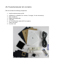
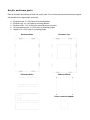
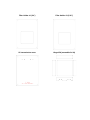
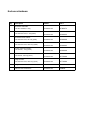
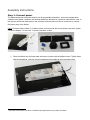
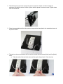
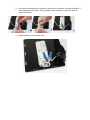
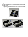
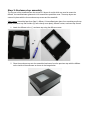
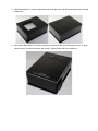
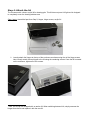
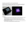
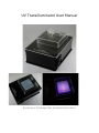
UV Transilluminator User Manual
Enclosure v 2.0 design files and build instructions
Introduction
Open source enclosure design files
UV Transilluminator kit contents
Acrylic enclosure parts
Enclosure Hardware
Assembly Instructions
Step 1: Connect power
Step 2: Enclosure base assembly
Step 3: Enclosure top assembly
Step 4: Attach the lid
Viewing a gel with the UV Transilluminator
Introduction
UV-transilluminators are used in molecular biology labs to view DNA (or RNA) that has been separated
by electrophoresis through an agarose gel. During or immediately after electrophoresis, the agarose gel
is stained with a fluorescent dye which binds to nucleic acid. Exposing the stained gel to a UVB light
source causes the DNA/dye to fluoresce and become visible. This technique is used wherever the
researcher needs to be able to view their sample, for example sizing a PCR product, purifying DNA
segment after a restriction enzyme digest, quantifying DNA or verifying RNA integrity after extraction.
This User Manual describes how to make a narrowband UV-B transilluminator with a 7.5 x 7.5 cm
window suitable for viewing and imaging DNA mini-gels. The kit contains all of the materials for making
the transilluminator. Assembly time is approx. 30-60 mins. No additional tools required.
Specifications:
●
●
●
Enclosure: 19.8 cm long x 14.9 cm wide x 6.5 cm tall
Viewing window: 7.5 cm x 7.5 cm
Output wavelength: 305-315 nm with a peak at 311 nm. See attached spec sheet for more
information on the UVB bulb
Open source enclosure design files
All of the enclosure designs files and BOM for the transilluminator are published by IO Rodeo on our
bitbucket site under Open Source licenses. The design of this current version 2.0 of the UV
Transilluminator is a slight modification of the UV Transilluminator v 1.0 described in a previous
Instructable tutorial. The design has been modified slightly as described below:
●
●
●
●
●
●
●
●
Viewing window increased to 7.5 cm x 7.5 cm (v 1.0 was 7 cm2)
Design now includes a 9 cm2 UV transmissive diffuser which sits above the UV bulb
Power entry switch now sits on the side of the box for easier access within a commercial
Imaging Enclosure
Acrylic material used to make the five parts of the enclosure base and sides has been changed
to 1/8" black acrylic (v1.0 was 1/4" black acrylic)
An additional part on the top has been included in this design to prevent any light leakage
around the sides of the transilluminator glass
New enclosure dimensions: 19.8 cm long x 14.9 cm wide x 6.5 cm tall
Changes to the hardware (see the project on Bitbucket for the new BOM)
Safety lid (clear or amber) has been increased to 10 cm x 10 cm (v1.0 was 8.2 cm x 10 cm)
UV Transilluminator kit contents
Each kit contains the following components:
1.
2.
3.
4.
5.
6.
7.
8.
Acrylic enclosure parts and lid;
Hardware (4 x standoffs, 24 x screws, 2 x hinges, 2 x wire connectors);
Mini-screwdriver;
Ballast with lampholder;
UVB bulb;
UV Transilluminator glass (8.25 cm square);
Power connector;
6’ power cord
Acrylic enclosure parts
Each kit contains the following 16 laser cut acrylic parts. Five of the acrylic parts have been pre-tapped
with threads for the appropriate screw size:
●
●
●
●
●
Enclosure base: 2 x 8-32 holes for mounting ballast
Enclosure top: 4 x 4-40 holes for mounting diffuser
Enclosure side: 2 x 5-40 holes for mounting power connector
UV transmissive cover: 4 x 8-32 holes for mounting hinges
Hinged lid: 4 x 8-32 holes for mounting hinges
Enclosure Base
Enclosure Top
Enclosure Sides
Solacryl diffuser
Power connector adapter
Filter Holder #1 (1/4”)
Filter Holder #2 (1/16”)
UV transmissive cover
Hinged lid (assembled in kit)
Enclosure Hardware
Qty
Description
Vendor
Part #
4
Enclosure standoffs:
mcmaster-carr
91780A174
mcmaster-carr
91249A123
mcmaster-carr
91249A108
mcmaster-carr
91249A102
mcmaster-carr
91249A108
mcmaster-carr
91772A188
8-32 machine screw, 3/16” long (silver)
mcmaster-carr
91771A189
2
Hinges
mcmaster-carr
1598A52
2
Twist-on wire connectors
mcmaster-carr
7108K81
4-40 hex standoffs, 2” long
4
Enclosure top screws:
4-40 machine screw, 1” long (black)
4
Enclosure base screws:
4-40 machine screw, 3/8” long (black)
4
Diffuser screws:
4-40 machine screw, 3/16” long (black)
2
Power connector screws:
5-40 Thread, ½" long (silver)
2
Ballast screws:
8-32 Thread, 1/8" long (silver)
8
Hinge screws:
Assembly Instructions
Step 1: Connect power
The ballast and power entry with switch in the kit are partially assembled - wires have already been
soldered to the power connector and the lamp ballast as described in a previous Instructables 1 step. In
the step you will mount these parts to the enclosure and use twist-on wire nut connectors to connect
the power entry to the ballast.
Parts: Enclosure base; ballast; 2 x ballast screws; enclosure side with cutout; power connector; power
connector adapter; 2 x wire nuts; 2 x power connector screws.
1. Place the ballast onto the base plate and secure in place with the ballast screws. Tighten down
with the screwdriver. Note the correct orientation of the ballast on the base plate below.
1
http://www.instructables.com/id/UV-Transilluminator/step3/Connect-AC-power-to-ballast/
2. Thread the power connector through the power connector adapter and then through the
enclosure side with the cutout. Secure in place with the power connector screws. Tighten down
with the screwdriver.
3. Place the assembled part from the previous step onto the base plate in the orientation shown in
the picture below.
4. The twist-on wire nut connectors will be used to connect the two neutral (white) and live (black)
wires.
a. Take the ends of the two black wires and line up the frayed ends. Twist the wires
together.
b. Insert the wire bundle into the connector and twist the connector clockwise until tight. It
should fit tightly on the wires. Test by pulling on the connector to ensure if does not
come off the wires.
c. Repeat steps for the two white wires.
Step 2: Enclosure base assembly
Step 2 parts: Assembled part from Step 1; 3 x enclosure sides; 4 x enclosure standoffs; 4 x enclosure
base screws; UV-B bulb.
1. Take one of the enclosure base screws and thread it through the corner holes on the enclosure
base. On the opposite side of the enclosure, screw in one of the enclosure standoffs. Repeat for
all 4 corners of the enclosure base.
2. Insert the UV-B bulb into the ballast and place the remaining enclosure sides into the slots in the
enclosure base.
Step 3: Enclosure top assembly
The top part of the transilluminator has a total of 4 layers of acrylic which are used to mount the
diffuser, the transilluminator glass and a UV transmissive protective cover. These top layers are
secured in place with the four enclosure top screws and the standoffs.
Step 3 parts: Assembled part from Step 2; diffuser, UV transilluminator glass, four remaining acrylic top
plates (enclosure top, filter holders (2) and solacryl cover plate), diffuser screws, enclosure top screws.
1. Attach the diffuser to the ⅛” enclosure top using the diffuser screws.
2. Place the enclosure top onto the assembled enclosure from the previous step with the diffuser
on the inside of the enclosure as shown in the image below.
3. Place filter holder # 1 onto the enclosure top. Next, place the transilluminator glass into the filter
holder slot.
4. Next, place filter holder # 2 onto the enclosure followed by the UV-transmissive cover. In each
corner screw in the four enclosure top screws. Tighten down with the screwdriver.
Step 4: Attach the lid
The kit comes with a clear1 acrylic lid for viewing gels. This lid does not pass UV light and is designed
to completely cover the viewing window area.
Step 4 parts: Assembled part from Step 3; hinges, hinge screws, acrylic lid.
1. Loosely attach the hinges to the top of the enclosure as shown using four of the hinge screws.
Next, loosely attach the two hinges to the lid using the remaining screws. Once the lid is seated
on the enclosure, tighten all of the screws.
1
Note, this lid can be swapped with an amber lid. When switching between lids, simply unscrew the
hinges from the lid and replace it with the new lid.
Viewing a gel with the UV Transilluminator
Once you have your mini-gel prepared and stained, place it onto the transilluminator underneath the
hinged lid as shown in the Images below. Always operate the UV-B bulb with the hinged lid closed.
Switch on the transilluminator. At this point you should see your DNA bands.
Safety Notes:
1. The gel above has been stained with ethidium bromide. As ethidium bromide is a toxic chemical
with strict safety protocols, it is only recommended that you use this dye in a lab with
established handling, storage and waste disposal procedures in place. Other users are
strongly recommended to use the less toxic dyes such as SYBR-Safe instead, which can be
handled and disposed of more safely.
2. The transilluminator does come with a safety lid for viewing the gel. However, when the lid is not
in place, safety glasses must be worn when operating the UV-B bulb.