1
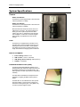
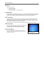
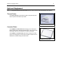
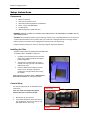
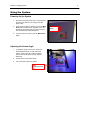
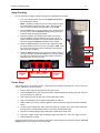
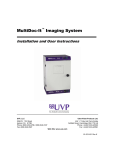
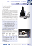
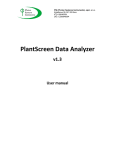
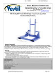
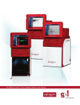
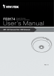
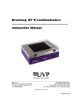
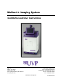
BioDoc-It® Imaging System Installation and User Instructions UVP, LLC 2066 W. 11th Street Upland, CA 91786 Phone: (800) 452-6788 / (909) 946-3197 Fax: (909) 946-3597 Ultra-Violet Products Ltd. Unit 1, Trinity Hall Farm Estate Nuffield Road, Cambridge CB4 1TG UK Phone: +44(0)1223-420022 Fax: +44(0)1223-420561 Web Site: www.uvp.com 81-0301-01 Rev E BioDoc-It Imaging Systems 2 System Introduction BioDoc-It® Imaging System The BioDoc-It Imaging System enables simple documentation of fluorescent and non-fluorescent gels, membranes, blots, film plates and assays with the ability to save images to a USB storage device for later quantitative analysis or enhancement for publication. Images are saved in 8-bit TIFF or JPEG formats, allowing saved images to be read by most PC or MAC programs. The BioDoc-It Imaging System is a cost effective solution for capturing quality images in a compact standalone package, as no external computer is required. The BioDoc-It comes in two configurations: BioDoc-It 220 Imaging System includes a high resolution, 1.3 megapixel camera, 8-48mm zoom lens and side access doors. BioDoc-It 210 Imaging System includes a 0.3 megapixel camera and an 8-48mm zoom lens. BioDoc-It Imaging Systems 3 System Components BioDoc-It Components Refer to the packing slip and pictured components for parts included with the system. FluorCam 210 or 220 Camera and Zoom Lens 8” LCD Touch Screen with Tilt Capability Filter Tray (located under the camera) with EtBr Filter USB Drive Main System Power Button Wide Access Door UV Gel Viewer Window White Light and Darkroom Power Switches UV to White Light Converter Plate (order separately) Side Access Doors (on BioDoc-It 220 models) Transilluminator BioDoc-It Imaging Systems System Specifications Camera BioDoc-It 220 Models: The BioDoc-It 220 is equipped with a FluorCam 220 Camera (resolution of 1.3MP). BioDoc-It 210 Models: The BioDoc-It 210 is equipped with a FluorCam 210 Camera (resolution of 0.3MP). Both the FluorCam 220 and FluorCam 210 use a USB 2.0 PC connection. All camera settings are factory pre-set for optimum performance when viewing gels, films, or membranes under low light level conditions. Contact UVP Technical Support before making any adjustments to the camera settings. Lens The BioDoc-It is equipped with an 8-48mm zoom lens fitted with a close-up diopter and step-up ring, allowing the camera to be held in a fixed position. The diopter is for focusing on objects at the focus length of the BioDoc-It Imaging System’s darkroom. Built-In Computer Internal Storage: 60GB or more USB 2.0 Ports: 1 front, 4 in the back USB Storage Device Capacity: 1GB (minimum) Software: TS software Ethidium Bromide Filter (EtBr) The Ethidium Bromide (EtBr) filter (50mm sq) UV blocking band pass interference filter blocks UV and IR radiation emitted from the transilluminator. The filter is placed in the filter tray below the camera/lens assembly. The filter allows visualization of fluorophores from 580-630nm, targeting the EtBr emission peak of 605nm. The EtBr filter can be substituted for other specific fluorophore filters or removed when imaging nonfluorescent media (protein gels, colony plates, etc.) in order to produce brighter images. 4 BioDoc-It Imaging Systems 5 Darkroom Darkroom features include: UV gel viewer window Overhead white light Wide access door with UV safety interlock switch Transilluminator A transilluminator is included with the BioDoc-It system. UVP offers a variety of transilluminators, from benchtop models with 8-watt, single wavelength and single intensity to models with multiple wavelengths and high/low intensities. UVP also offers the high-end FirstLight®, a highly uniform, 302nm UV transilluminator. LCD Touch Screen The display is an 8-inch VGA color touch screen with tilt adjustment connected to the darkroom cabinet. The touch screen allows the user to preview, snap, save and print images, as well as select certain preference options, without the need to use an external mouse or keyboard. However, should the user desire, a mouse and/or keyboard (not included) can be used with the BioDoc-It. A stylus pen is included for increased pointer control for selecting software options on the touch screen. UVP Focus Target The UVP Focus Target fluoresces when placed on a transilluminator or when exposed to overhead UV. The target provides sharp, fluorescent images to aid in adjusting the focus of the camera. Removable USB Stick The removable USB stick, included with the system, has 1GB memory (minimum) and connects to the system to allow for saving and transferring of images. UVP Focus Target BioDoc-It Imaging Systems 6 Optional Equipment Refer to the Replacement Parts and Accessories section of this manual for optional equipment part numbers. Thermal Printer The Thermal Printer provides archive quality, 256 grayscale prints and five optional cost-effective print sizes. Thermal Printer Converter Plates The UV/White Converter Plate allows imaging of non-fluorescent stained media with an ultraviolet transilluminator. The converter plate is specially coated to convert 302nm UV output to white light. The Visi-Blue™ Converter Plate (not shown) converts UV to 460470nm and is designed for use with blue excitation samples such as SYBR Green, SYPRO Orange and GFP stains. UV/White Converter Plate BioDoc-It Imaging Systems 7 Setup Instructions Components BioDoc-It Darkroom CCD Camera and Zoom Lens Camera/Lens Mounting Bracket and Hardware Power, Jumper and USB Cables Transilluminator USB Storage Device (1GB minimum) WARNING: DO NOT ATTEMPT TO CONNECT ANY WIRING WHILE THE EQUIPMENT IS CONNECTED TO THE POWER SUPPLY! CAUTION: Do not install the system in places with high moisture, dust, or high temperatures. Do not use any oil or petroleum based cleaners on the cabinet. Use only a mild soap or detergent solution for cleaning. Ensure that the system is turned OFF and is unplugged from its power source during cleaning. Keep the equipment away from motors or other large magnetic equipment apparatus. Installing the Filter Systems include a 50mm sq Ethidium Bromide (EtBr) filter. To install the filter in the BioDoc-It darkroom: 1. Carefully remove the filter from the protective plastic case, holding the filter at the edges to prevent fingerprints. 2. The filter tray is located under the camera bracket on the top right side of the darkroom. Slide the tray open. 3. Place the filter inside the filter tray. Ensure that the text on the edge of the filter is positioned so it is right side up when facing the installer. Additional filters are available. Refer to Replacement Parts and Accessories for ordering information. Camera Setup The camera and zoom lens are assembled at the UVP factory. Step-up ring Note: The zoom lens shipped may appear different than the one pictured at right. 1. Remove the cap from the lens. 2. If not already assembled, attach the step-up ring and diopter to the lens. The step up ring and diopter will only fit one way. Diopter BioDoc-It Imaging Systems 3. 4. Using the four brass thumb screws provided, secure the bracket to the base. Slide the camera and lens assembly into the camera bracket. Slide the lens through the center hole in the gasket on the base and use the gasket to form a light-tight seal around the lens. 8 Camera bracket Black thumb screw Camera USB cable Camera and lens assembly Brass thumb screws secure the bracket to the base 5. Insert and tighten the black thumb screw and washer in the central hole in the camera to secure the camera to the bracket. 6. Plug the camera cable into the top of the camera and the other end into a USB port on back of the darkroom. 7. Connect the jumper cord from the darkroom to the transilluminator. 8. Connect the main power cord from the back of the darkroom to a surge-protected power outlet. Base Connection for the main darkroom power Connection for jumper cord to the transilluminator USB port Stylus and Holder The BioDoc-It screen is touch sensitive. Use the stylus included with the system to operate the software controls. For easy access to the stylus when operating the system, remove the tape from the back of the stylus holder and adhere it to the BioDoc-It. Slide the stylus into the holder. BioDoc-It Imaging Systems 9 Using the System Powering Up the System 1. Ensure that the main power cord is connected from the back of the darkroom to a surge-protected power outlet. 2. Power up the system by pressing once on the Main Power button located on the right side of the unit. All internal components will now have power and the TS software will automatically load. 3. To power down the system, push the Main Power button. Adjusting the Screen Angle 1. To adjust the angle of the screen, loosen the black rubberized knobs on each side of the monitor. Twist each knob counter-clockwise (note that the knobs will be turning opposite directions). 2. Tilt the screen to the desired angle. 3. Turn each knob clockwise to tighten. Black Rubberized Knob Main Power Button BioDoc-It Imaging Systems 10 Operating the TS Software Once the Main Power button is pressed, the system will go through the boot-up process. Upon completion, the LCD monitor will display the TS software screen similar to the one below: To shut down the TS software, touch the X on the bottom left corner of the screen. To turn the system off, press the Main Power button or power down from the Windows icon on the bottom right corner of the screen. Refer to the TS Software User Manual for further instructions on using the software. Using the Transilluminator Once the BioDoc-It darkroom power is turned on, power is supplied to all components. This includes the jumper cable that supplies power to the transilluminator. To use the transilluminator, turn ON the two transilluminator power switches. One switch is on the front of the BioDoc-It unit and is labeled UV Trans. The other switch is located on the front of the transilluminator itself, directly below the darkroom door. Refer to the Transilluminator Manual for additional instructions on using the transilluminator. Using the UV Gel Viewer Window The UV Gel Viewer Window has a metal cover to block out ambient lighting and to protect the UV-safe glass. The cover is held in the closed position by two small magnets built into the UV-safe glass. To open the window cover, pull down on the metal tab. The cover will pop open. To close the cover, pivot it up until it reengages with the two small magnets. The glass is UV blocking while providing a clear, UV-safe view to the transilluminator surface for visibility of samples. Metal tab BioDoc-It Imaging Systems 11 Image Focusing Prior to capturing any images, prepare the image focus capabilities of the system: 1. Turn on the transilluminator and place the UVP Focus Target on the transilluminator surface. NOTE: The BioDoc-It darkroom has a UV safety switch that turns the transilluminator off when the door is open. After closing the door, be sure the overhead white light switch is turned OFF. 2. Press the LIVE button on the TS software screen. While watching the LCD screen, rotate the Aperture adjustment ring on the lens so that the image is as bright as possible. 3. Using the integration time settings at the bottom of the screen, press the mSec time interval selector square. Then, use the + button to increase integration time until the desired brightness is achieved. Readjust the Aperture adjustment ring if needed. 4. Rotate the Focus adjustment ring on the lens. Adjust this so that the image appears in clear focus on the LCD monitor. Note: Once the proper zoom range is set, the lens will have to be refocused when zoomed in completely. 5. Rotate the Zoom adjustment ring on the lens so that the image is as large as possible. Readjust the Focus ring on the lens, making the image clear. Adjust the zoom so that the object of interest is within the picture on the LCD monitor. Aperture Zoom Focus Decrease Integration Time Min / Sec / mSec Time Interval Selectors Increase Integration Time Printer Setup The thermal printer is an optional accessory. If this order did not include a thermal printer, move on to the next section. Otherwise, to set up the printer: 1. Plug the power cable from the printer into the power source. 2. Press the Open button to open the lid of the printer and load the paper by allowing the loose end of the roll to come off the top of the roll. 3. After shutting the printer lid, tear off the excess paper that is visible. 4. Plug in the USB cable from the printer into the BioDoc-It USB port. 5. With the BioDoc-It turned on, press the “Windows” button on the lower-right portion of the TS software screen. 6. To set the printer settings click “Start” at the lower left of the computer. Next, click “Printers and Faxes”, then right-click on the appropriate printer icon and select “Printing Preferences”. 7. Choose the following settings: High Density paper, 1280X1280, Portrait mode. 8. Click on the “Option” tab and click the “Enlarge Image to Fit Paper” box. Then, click “Apply” and “OK”. 9. Restart the BioDoc-it system. If the thermal printer does not work correctly, contact UVP Technical Support for assistance. See the Technical Support section of this manual for contact information. BioDoc-It Imaging Systems 12 Service Procedures Return Procedure A Returned Goods Authorization (RGA) number must be obtained from UVP Customer Service before returning any product. Replacement Parts and Accessories To order accessories or replacement parts for the BioDoc-It Imaging System, contact UVP’s offices. Part Description Part Number Filter, Ethidium Bromide, 50mm Square Filter, SYBR Green, 50mm Square Filter, SYBR Gold, 50mm Square 38-0220-01 38-0219-01 38-0221-01 White Light Converter Plate, 21x26cm White Light Converter Plate, 25x26cm Visi-Blue Converter Plate, 21x26cm Visi-Blue Converter Plate, 25x26cm 38-0191-01 38-0191-04 38-0200-01 38-0200-04 Gel-Cutter Gel-Ruler Gel-Scooper Gel-Tray, small Gel-Sentry DNA Preparation Plate Fluorescent Standard Step Tablet 85-0002-01 85-0003-01 85-0006-01 85-0007-01 97-0076-01 33-0014-02 ® Doc-It LS Analysis Software 97-0185-02 Spectacles, UV Blocking (UVC-303) Goggles, UV Blocking (UVC-503) Faceshield, UV Blocking (UVC-803) 98-0002-01 98-0002-02 98-0002-04 Troubleshooting No Power to the Darkroom or Transilluminator 1. Recheck the main power cord connection to the BioDoc-It darkroom as well as the power cables between the darkroom and transilluminator. 2. Check the fuses located at the back of the unit next to the power port. A flat-head screwdriver will be required. Turn the fuseholder cap counterclockwise and the fuse holder will pop out. Inspect the thin wire within the glass fuse to see if there is a break in the wire. If so, replace the fuse(s). If fuses are blowing repeatedly, contact UVP Technical Support for additional troubleshooting. Transilluminator Will Not Turn On 1. Make sure to turn ON the two transilluminator power switches and that both switches are glowing green. One switch is on the front of the BioDoc-It unit and is labeled UV Trans. The other switch is located on the front of the transilluminator itself, directly below the darkroom door. If the switches do not glow green, refer to “No Power to the Darkroom or Transilluminator” above. 2. Be sure the darkroom cabinet’s door is completely closed. There is a UV exposure safety cut-off switch that turns the transilluminator off when the darkroom cabinet’s door is opened. 3. Be sure the transilluminator’s power jumper cord is securely connected at both the ends of the cable. BioDoc-It Imaging Systems 13 Touch Screen Not Accurate 1. If touching or clicking on the buttons becomes inaccurate, the touch screen may need to be recalibrated. Please follow all instructions in the touch screen calibration instructions included in the TS software CD. Error Messages Appear on the Screen 1. An error message that is related to the TS software interface or Microsoft Windows may appear on the screen. If the message is related to Microsoft Windows, such as a reminder to activate or update the copy of Windows, please contact your system administrator for assistance. 2. If an error message appears repeatedly and your system administrator does not recognize it as a Microsoft Windows error, contact UVP Technical Support for further assistance. Technical Support UVP offers technical support on all of its products. If there are questions about the product’s use, operation or repair, please contact UVP’s offices at the locations below. Or go to UVP’s web site and click the Tech Support > BioImaging Systems. If in North America, South America, East Asia or Australia: If in Europe, Africa, the Middle East of Western Asia: Call (800) 452-6788 or (909) 9463197, and ask for Customer Service during regular business days, between 7:00 am and 5:00 pm, PST. Call +44(0) 1223-42002, and ask for Customer Service during regular business days between 9:00 am and 5:30 pm. E-mail your message to: [email protected] E-mail your message to: [email protected] Fax Customer Service, and send it to (909) 946-3597 Fax Customer Service, and send it to: +44(0) 1223-420561 Write to: UVP, LLC 2066 W. 11 Street, Upland, CA 91786 USA th Write to: Ultra-Violet Products Ltd Unit 1, Trinity Hall Farm Estate, Nuffield Road, Cambridge CB4 1TG UK Warranty UVP's products are guaranteed to be free of defects in materials, workmanship and manufacture for one (1) year from date of purchase. Consumable and disposable parts including, but not limited to tubes and filters, are guaranteed to be free from defects in manufacture and materials for ninety (90) days from date of purchase. Transilluminators carry a two (2) year warranty from date of purchase. If equipment failure or malfunction occurs during the warranty period, UVP shall examine the inoperative equipment and have the option of repairing or replacing any part(s) which, in the judgment of UVP, were originally defective or became so under conditions of normal usage and service. No warranty shall apply to this instrument, or part thereof, that has been subject to accident, negligence, alteration, abuse or misuse by the end-user. Moreover, UVP makes no warranties whatsoever with respect to parts not supplied by UVP or that have been installed, used and/or serviced other than in strict compliance with instructions appearing in this manual. In no event shall UVP be responsible to the end-user for any incidental or consequential damages, whether foreseeable or not, including but not limited to property damage, inability to use equipment, lost business, lost profits, or inconvenience arising out of or connected with the use of instruments produced by UVP. Nor is UVP liable or responsible for any personal injuries occurring as a result of the use, installation and/or servicing of equipment. This warranty does not supersede any statutory rights that may be available in certain countries. BioDoc-It, Doc-It and FirstLight are registered trademarks of UVP, LLC. Visi-Blue is a trademark of UVP, LLC.