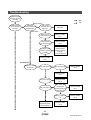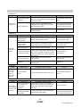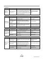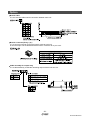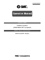
1
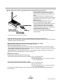
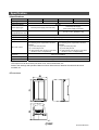
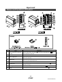
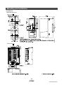
No.EX##-OMI0032-B PRODUCT NAME Fieldbus system (PROFIBUS DP compliant) MODEL / Series / Product Number EX510-GPR1 Series Table of Contents Safety Instructions 3 Model Indication and how to order 8 Names and Functions of Product 9 Definition and terminology 10 Common Specification 12 EX510 GW Unit Names and Functions of Product 13 Mounting and Installation 14 Installation 14 Wiring 15 Setting 19 Specification 31 Specifications 31 Dimensions 32 SI Unit Names and Functions of Product 33 Mounting and Installation 35 Installation 35 Wiring 36 Setting 40 Specification 40 Specifications 40 Dimensions 41 Output Unit Names and Functions of Product 42 Mounting and Installation 43 Installation 43 Wiring 44 Specification 47 Specifications 47 Dimensions 47 -1No.EX##-OMI0032-B Input Unit Names and Functions of Product 48 Mounting and Installation 49 Installation 49 Wiring 51 Specification 54 Specifications 54 Dimensions 54 Maintenance 55 Troubleshooting 56 Option 61 -2No.EX##-OMI0032-B Safety Instructions These safety instructions are intended to prevent hazardous situations and/or equipment damage. These instructions indicate the level of potential hazard with the labels of "Caution", "Warning" or "Danger". They are all important notes for safety and must be followed in addition to International standards (ISO/IEC)*1) and other safety regulations. *1) ISO 4414: Pneumatic fluid power -- General rules relating to systems ISO 4413: Hydraulic fluid power -- General rules relating to systems IEC 60204-1: Safety of machinery -- Electrical equipment of machines (Part 1: General requirements) ISO 10218-1: Manipulating industrial robots -Safety. etc. Caution : Warning : Danger : CAUTION indicates a hazard with a low level of risk which, if not avoided, could result in minor or moderate injury. WARNING indicates a hazard with a medium level of risk which, if not avoided, could result in death or serious injury. DANGER indicates a hazard with a high level of risk which, if not avoided, will result in death or serious injury. Warning 1. The compatibility of the product is the responsibility of the person who designs the equipment or decides its specifications. Since the product specified here is used under various operating conditions, its compatibility with specific equipment must be decided by the person who designs the equipment or decides its specifications based on necessary analysis and test results. The expected performance and safety assurance of the equipment will be the responsibility of the person who has determined its compatibility with the product. This person should also continuously review all specifications of the product referring to its latest catalog information, with a view to giving due consideration to any possibility of equipment failure when configuring the equipment. 2. Only personnel with appropriate training should operate machinery and equipment. The product specified here may become unsafe if handled incorrectly. The assembly, operation and maintenance of machines or equipment including our products must be performed by an operator who is appropriately trained and experienced. 3. Do not service or attempt to remove product and machinery/equipment until safety is confirmed. 1. The inspection and maintenance of machinery/equipment should only be performed after measures to prevent falling or runaway of the driven objects have been confirmed. 2. When the product is to be removed, confirm that the safety measures as mentioned above are implemented and the power from any appropriate source is cut, and read and understand the specific product precautions of all relevant products carefully. 3. Before machinery/equipment is restarted, take measures to prevent unexpected operation and malfunction. 4. Contact SMC beforehand and take special consideration of safety measures if the product is to be used in any of the following conditions. 1. Conditions and environments outside of the given specifications, or use outdoors or in a place exposed to direct sunlight. 2. Installation on equipment in conjunction with atomic energy, railways, air navigation, space, shipping, vehicles, military, medical treatment, combustion and recreation, or equipment in contact with food and beverages, emergency stop circuits, clutch and brake circuits in press applications, safety equipment or other applications unsuitable for the standard specifications described in the product catalog. 3. An application which could have negative effects on people, property, or animals requiring special safety analysis. 4. Use in an interlock circuit, which requires the provision of double interlock for possible failure by using a mechanical protective function, and periodical checks to confirm proper operation. -3No.EX##-OMI0032-B Caution The product is provided for use in manufacturing industries. The product herein described is basically provided for peaceful use in manufacturing industries. If considering using the product in other industries, consult SMC beforehand and exchange specifications or a contract if necessary. If anything is unclear, contact your nearest sales branch. Limited warranty and Disclaimer/Compliance Requirements The product used is subject to the following "Limited warranty and Disclaimer" and "Compliance Requirements". Read and accept them before using the product. Limited warranty and Disclaimer 1. The warranty period of the product is 1 year in service or 1.5 years after the product is delivered.∗2) Also, the product may have specified durability, running distance or replacement parts. Please consult your nearest sales branch. 2. For any failure or damage reported within the warranty period which is clearly our responsibility, a replacement product or necessary parts will be provided. This limited warranty applies only to our product independently, and not to any other damage incurred due to the failure of the product. 3. Prior to using SMC products, please read and understand the warranty terms and disclaimers noted in the specified catalog for the particular products. ∗2) Vacuum pads are excluded from this 1 year warranty. A vacuum pad is a consumable part, so it is warranted for a year after it is delivered. Also, even within the warranty period, the wear of a product due to the use of the vacuum pad or failure due to the deterioration of rubber material are not covered by the limited warranty. Compliance Requirements 1. The use of SMC products with production equipment for the manufacture of weapons of mass destruction (WMD) or any other weapon is strictly prohibited. 2. The exports of SMC products or technology from one country to another are governed by the relevant security laws and regulation of the countries involved in the transaction. Prior to the shipment of a SMC product to another country, assure that all local rules governing that export are known and followed. -4No.EX##-OMI0032-B Operator ♦This operation manual is intended for those who have knowledge of machinery using pneumatic equipment, and have sufficient knowledge of assembly, operation and maintenance of such equipment. Only those persons are allowed to perform assembly, operation and maintenance. ♦Read and understand this operation manual carefully before assembling, operating or providing maintenance to the product. ■Precautions Warning ■Do not disassemble, modify (including changing the printed circuit board) or repair. An injury or failure can result. ■Do not operate the product outside of the specifications. Do not use for flammable or harmful fluids. Fire, malfunction, or damage to the product can result. Verify the specifications before use. ■Do not operate in an atmosphere containing flammable or explosive gases. Fire or an explosion can result. This product is not designed to be explosion proof. ■If using the product in an interlocking circuit: •Provide a double interlocking system, for example a mechanical system. •Check the product regularly for proper operation. Otherwise malfunction can result, causing an accident. ■The following instructions must be followed during maintenance: •Turn off the power supply. •Stop the air supply, exhaust the residual pressure and verify that the air is released before performing maintenance. Otherwise an injury can result. Caution ■After maintenance is complete, perform appropriate functional inspections. Stop operation if the equipment does not function properly. Safety cannot be assured in the case of unexpected malfunction. ■Provide grounding to assure the safety and noise resistance of the GW unit. Individual grounding should be provided close to the product with a short cable. -5No.EX##-OMI0032-B ■NOTE ○Follow the instructions given below when designing, selecting and handling the product. •The instructions on design and selection (installation, wiring, environment, adjustment, operation, maintenance, etc.) described below must also be followed. ∗Product specifications •The direct current power supply to combine should be UL1310 Class2 power supply when conformity to UL is necessary. •Use the specified voltage. Otherwise failure or malfunction can result. •Reserve a space for maintenance. Allow sufficient space for maintenance when designing the system. •Do not remove any nameplates or labels. This can lead to incorrect maintenance, or misreading of the operation manual, which could cause damage or malfunction to the product. •Product handling ∗Installation •Do not drop, hit or apply excessive shock to the fieldbus system. Otherwise damage to the product can result, causing malfunction. •Tighten to the specified tightening torque. If the tightening torque is exceeded the mounting screws may be broken. •Never mount a product in a location that will be used as a foothold. The product may be damaged if excessive force is applied by stepping or climbing onto it. ∗Wiring •Avoid repeatedly bending or stretching the cables, or placing heavy load on them. Repetitive bending stress or tensile stress can cause breakage of the cable. •Wire correctly. Incorrect wiring can break the product. •Do not perform wiring while the power is on. Otherwise damage to the fieldbus system and/or I/O device can result, causing malfunction. •Do not route wires and cables together with power or high voltage cables. Otherwise the fieldbus system and/or I/O device can malfunction due to interference of noise and surge voltage from power and high voltage cables to the signal line. Route the wires (piping) of the fieldbus system and/or I/O device separately from power or high voltage cables. •Confirm proper insulation of wiring. Poor insulation (interference from another circuit, poor insulation between terminals, etc.) can lead to excess voltage or current being applied to the product, causing damage. •Take appropriate measures against noise, such as using a noise filter, when the fieldbus system is incorporated into equipment. Otherwise noise can cause malfunction. •Separate the power line for output devices from the power line for input devices and controlling GW. Otherwise noise or induced surge voltage can cause malfunction. -6No.EX##-OMI0032-B ∗Environment •Do not use the product in area that is exposed to corrosive gases, chemicals, sea water, water or steam. Otherwise failure or malfunction can result. •Do not use in an area where surges are generated. If there is equipment which generates a large amount of surge (solenoid type lifter, high frequency induction furnace, motor, etc.) close to the fieldbus system, this may cause deterioration or breakage of the internal circuit of the fieldbus system. Avoid sources of surge generation and crossed lines. •When a surge-generating load such as a relay or solenoid is driven directly, use an fieldbus system with a built-in surge absorbing element. Direct drive of a load generating surge voltage can damage the fieldbus system. •The product is CE marked, but not immune to lightning strikes. Take measures against lightning strikes in the system. •Prevent foreign matter such as remnant of wires from entering the fieldbus system to avoid failure and malfunction. •Mount the product in a place that is not exposed to vibration or impact. Otherwise failure or malfunction can result. •Do not use the product in an environment that is exposed to temperature cycle. Heat cycles other than ordinary changes in temperature can adversely affect the inside of the product. •Do not expose the product to direct sunlight. If using in a location directly exposed to sunlight, shade the product from the sunlight. Otherwise failure or malfunction can result. •Keep within the specified ambient temperature range. Otherwise malfunction can result. •Do not operate close to a heat source, or in a location exposed to radiant heat. Otherwise malfunction can result. ∗Adjustment and Operation •Set the switches by using a sharp-pointed screwdriver etc. It may damage set switches. •Perform settings suitable for the operating conditions. Incorrect setting can cause operation failure. For details of each setting, refer to page 20 to 30 of this manual •Please refer to the PLC manufacturer's manual etc. for details of programming and addresses. For the PLC protocol and programming refer to the relevant manufacturer's documentation. ∗Maintenance •Turn off the power supply, stop the supplied air, exhaust the residual pressure and verify the release of air before performing maintenance. There is a risk of unexpected malfunction. •Perform regular maintenance and inspections. There is a risk of unexpected malfunction. •After maintenance is complete, perform appropriate functional inspections. Stop operation if the equipment does not function properly. Otherwise safety is not assured due to an unexpected malfunction or incorrect operation. •Do not use solvents such as benzene, thinner etc. to clean the each unit. They could damage the surface of the body and erase the markings on the body. Use a soft cloth to remove stains. For heavy stains, use a cloth soaked with diluted neutral detergent and fully squeezed, then wipe up the stains again with a dry cloth. -7No.EX##-OMI0032-B Model Indication and how to order •GW unit: PROFIBUS DP compatible •Input unit •SI unit •Output unit For the detail of part no. of solenoid valve manifold and independent solenoid valve with SI unit, refer to Operation Manual or other equivalent documents of used solenoid valve. -8No.EX##-OMI0032-B Names and Functions of Product •System structure •Capable of decentralized control of 64 input points/64 output points. Decentralized control of 4 input branches (maximum points of 16×4 branches) and 4 output branches (maximum points of 16×4 branches) per one GW unit is possible. •Easy setting and wiring Slave side does not need switch settings, but GW unit needs them such as address setting. It is possible to adjust length of branch cable and crimp branch cable without dedicated tool. Each slave does not need individual power supply because the branch cable is 4-core flat cable including a power supply line. •Compact design Small and compact design is applied for all of GW unit which realizes decentralized control, Input unit which connects input equipments such as sensor, and SI unit which connects output equipment such as solenoid valve. •Flexible setting of number of occupied station Utilize I/O point effectively by setting number of occupied station of GW unit. •Applicable to each type of solenoid valves SMC’s solenoid valves can be easily wired for serial communication. (See Manifold Valve for applicable valve.) The extra output of SI unit can be used to actuate 2-port valve etc, with a cable assembly for output. -9No.EX##-OMI0032-B ■Definition and terminology Terms A B C D E Meaning Address (Station address) A number allocated to identify the unit connected on the PROFIBUS DP network. It is not allowed to be duplicated. Attenuation factor A dissipation of signal wave form in proportion to a length of communication line. Normally, indicated by dB/ft (decibel per feet). BF Abbreviation of BUS FAULT. It shows the communication of the GW unit. Branch wiring A method to branch and connect a communication line and power line from GW unit to SI unit and Input unit. Class 2 master Master for control, commissioning, and configuration functions. Communication connector A connecting part to transmit a communication signal which goes and returns between equipments in field bus. Communication port A connection port to distribute a communication line and power line from GW unit to SI unit and Input unit. Communication speed A speed at which data is sent and received in field bus etc. It depends on an equipment (PLC etc.) at high side and is indicated by bps (bit per second). Connector lock pin A pin that prevents the connector for connecting load to be connected to SI unit from coming off. Conductor resistance A electric resistance of a conductor. It is a value to show ease of current flow. Current consumption A current necessary to operate a product normally. In this case, the current applied to a load is not included. Current sink type (NPN output) An output configuration of an input equipment which uses NPN transistor for signal outputting part. It sinks current with input and that is the reason why it is called sink. Current source type (PNP output) An output configuration of an input equipment which uses PNP transistor for signal outputting part. It sources current with input and that is the reason why it is called source. Data rate An amount of data which can be sent from one equipment to the other equipment. Referred to as transmission speed of data. DIN rail A metallic rail conforming with DIN (German Federation) standard. DIA Abbreviation of Diagnosis. It shows the GW unit status. Enclosure (IP) An abbreviation of Ingress Protection. It is a standard related to protection of a product from foreign matters (hand, steel ball, steel wire, dust, water etc.). Diagnosis information from GW unit. It is composed of standard diagnosis Enhancing diagnosis information information provided with PROFIBUS DP and peculiar diagnosis information to the GW unit. F FG An abbreviation of frame ground meaning a body ground. Used to show a ground simply. Field bus A standard which uses digital communication to transmit a signal between an equipment running at factory and field (instrumentation and operation equipment) and controller. FREEZE function Function that input data of GW unit synchronizes with FREEZE command from master. GND An abbreviation of ground meaning reference voltage for signal. It has a same potential level as a shield wire (sheath) of signal line and connector and is referred to as a reference potential to transmit an electrical signal. GSD file File which describes the master data of product. G -10No.EX##-OMI0032-B No. Terms G I L M GW unit A unit used to connect protocols conforming with different standards in one network. In this system, it is regarded as a unit to adjust between PROFIBUS DP protocol and SMC dedicated protocol and connect them. ID number Number of 16bit allocated from PNO to identify product. Impedance A resistance generated when alternating current is applied to a circuit. Referred to as alternating current resistance. Input delay time Refer to "Transmission delay". Input point The number of point which can receive information from an input equipment (sensor, switch etc.). LED An abbreviation of Light Emitting Diode meaning a kind of semiconductor element which emits light when current is applied. Manifold A component used to join many valves into one. NPN output An output configuration which operates an output equipment by using NPN transistor. Referred to as positive common type because positive potential is applied to common wire of power supply. Opt-coupler insulation A method for insulation by converting an electric signal to an optic signal once and using an element called opt-coupler which shows "1" and "0" when turned on and off. An opt-coupler has a part to convert an electric signal to an optic signal or opposite of it and so can be separated electrically and insulated. Output point The number of point which can operate an output equipment (solenoid valve, light and motor starter etc.) N O P PLC An abbreviation of Programmable Logic Controller. It controls timely along with a (Programmable Logic Controller) program for logic algorithm, sequential operation and arithmetic operation. PNP output An output configuration which operates an output equipment by using PNP transistor. Referred to as negative common type because negative potential is applied to common wire of power supply. Power supply connector A connecting part to apply power to a product. Power supply voltage range A range of power supply voltage to operate a product normally. PROFIBUS DP Fieldbus jointly developed by Siemens, Bosch, ABB, etc. in Germany in 1980’s. PNO (PROFIBUS Nutzerorganisation e.V) starts for the PROFIBUS DP spread. Rated voltage A optimum value of power supply voltage applied to a product. It can ensure normal operation of a product with this voltage in specified operating environment. Serial transmission A method to enable large information to be sent and received sequentially in one communication line by aligning them in line. Short protection A method to protect an internal circuit from being damaged when power supply and GND terminal are shorted. SI unit An abbreviation of serial interface. It sends and receives data by bit through a couple of signal lines, convert it to parallel and correspondingly control connected load. (A serial-to-parallel converting unit) SYNC function A function that the output data of the GW unit synchronizes with the SYNC command from the master. Terminating resistor A resistor mounted on both ends of wiring for connecting equipment to field bus. It prevents reflection of a signal at the end and subsequent disturbance of the signal. Transmission delay A time delay from when a specified input passes a reference point until when an output reaches the reference point. R S Meaning T -11No.EX##-OMI0032-B Common Specification •EX510 series common specifications Item Rated voltage Specification 24 VDC Allowable instantaneous electrical stop 1 msec. or less Protection class IP20 Applicable standard UL/CSA, CE Withstand voltage 500 VAC 1 minute (between FG and external terminal block) Insulation resistance 10 MΩ or more (500 VDC is given between FG and external terminal block) Ambient temperature Operating: -10 to 50 oC Storage: -20 to 60 oC Ambient humidity 35% to 85%RH (No dew condensation) Operating environment No corrosive gas Pollution degree For use in Pollution Degree 2 Environment -12No.EX##-OMI0032-B EX510 GW unit Names and Functions of Product No. Parts Purpose 1 Communication socket (BUS) Connect to PROFIBUS DP line with a communication connector for PROFIBUS DP ( ). Connect a terminating resistor ( ) to both end units of a transmission route. 2 Power supply socket (PWR(V)) Supplying power for output devices such as a solenoid valve with a power supply connector ( ). 3 Power supply socket (PWR) Supplying power for controlling GW and for input devices such as a sensor with a power supply connector ( ). 4 GW unit side branch connector (for input) Connecting an Input unit etc. by using branch cables (EX510-FC 5 GW unit side branch connector (for output) Connecting an SI unit (manifold valve) etc. by using branch cables (EX510-FC ). 6 Ground terminal (FG) Used for grounding. 7 Mounting hole Used when an unit is mounted with two M4 screws. 8 DIN rail mounting slot Used when an unit is mounted to DIN rail. 9 Display/switch setting part Sets up the switch on such as LED display and address, I/O points. ). -13No.EX##-OMI0032-B Mounting and Installation ■Installation •Screw installation •DIN rail installation Put claw 1 of the body under DIN rail and push it upward. Push down Claw 2 to the opposite rail until the claw clicks securely on to rail. (Mounting procedure and ) For removing, lever up the DIN rail fixing plate of the body with a flat blade screwdriver, and remove it by tilting Claw 2 side forward. (Removal procedure and ) -14No.EX##-OMI0032-B ■Wiring •Internal circuit and wiring The wirings are described in the following order. 1. Communication wiring: Connection with PROFIBUS DP. ↓ 2. Power supply wiring: Connections of power supplies for output and input devices and controlling GW. ↓ 3. Branch wiring: Connection from GW unit to SI unit or Input unit. -15No.EX##-OMI0032-B 1. Communication wiring The method to connect a PROFIBUS DP detected cable and a GW unit PROFIBUS DP communication connector is shown below. Connecting cable •Make sure to connect the signal cables to designated pins (Refer to Fig. 1). •Be sure to connect a "Terminating resistor" to both ends of transmission line. (Refer to Fig. 2). Tighten the connector securely to 0.5 to 0.6 Nm tightening torque. Connecting terminating resistor •Be sure to connect a terminating resistor to both ends of transmission line (Refer to Fig. 3). Tighten the connector securely to 0.5 to 0.6 Nm tightening torque. •The terminating resistor to be used differs depending on the specification of the cable. The following terminal resistance value is based on the specification of type A cable. -16No.EX##-OMI0032-B 2. Power supply wiring Connect power supply wiring to the two power supply 2-pin connectors. Power supply consists of 2 systems, but they it can be used with both of single power supply and separate power supplies. Also, other units do not need individual power supply. Make sure of connection with the designated pin. Tighten the connector securely to 0.5 to 0.6 Nm tightening torque. Refer to Fig. 4 about how to connecting. When SI unit etc. (EX510-S 0 ) is used besides the external power supply type Output unit, it is necessary to supply power for output to the GW unit and the Output unit. NOTE Ground the FG terminal. -17No.EX##-OMI0032-B 3. Branch wiring Each unit is wired with a branch cable, and connected with a branch connector. Two branch connectors are attached to each of SI unit, Input unit and Output unit. Pressure welding for branch connector The method of pressure welding for branch connector is explained. -18No.EX##-OMI0032-B Wiring of branch cables How to connect branch cable is shown below. Connect the branch connectors for GW unit in order from the bottom one (COM A, B, C, and D). Setting •Display for setting Display PWR(V) Contents The power for output is supplied at specified voltage: Lights up The power for output is not supplied at specified voltage: Goes off RUN The power for input and GW unit controlling part is supplied: Lights up The power for input and GW unit controlling part is not supplied: Goes off DIA ∗1 DIA error: Lights up Normal DIA: Goes off BF PROFIBUS DP communication error: Lights up Normal PROFIBUS DP communication: Goes off COM A COM A is receiving data: Lights up ∗2 COM A is having no data to receive: Goes off COM B COM B is receiving data: Lights up ∗2 COM B is having no data to receive: Goes off COM C COM C is receiving data: Lights up ∗2 COM C is having no data to receive: Goes off COM D COM D is receiving data: Lights up ∗2 COM D is having no data to receive: Goes off ∗1: DIA LED lights up in red when the Input unit connected to the input port (COM A-D) is not in a normal status (open fuse, broken wire, miswriting, loosening of joint of the branch cable) or the Input unit is not connected. DIA LED does not light up in red if the Input unit is connected to the unused input port. ∗2: Only when Input is connected and communicated normally. COM A-D LED does not light up if the port is not set to be “used” by input point setting. -19No.EX##-OMI0032-B •Switch setting NOTE 1. Open the cover, and set DIP switch with a flat blade driver, etc. 2. Make sure that switch setting is performed with power supply turned off. 3. Be sure to perform this setting of the switch before use. 1. Setting of Address • UNIT STATUS • HOLD/CLR • HW/SW mode (SW1) Setting of address is performed with SW1. •Address setting (Switch No.1 to 7) All setting are turned OFF at shipment and the Address is set to 0. Make sure to set the Address within the range of 0 to 125. ADDRESS 64(No.1) 32(No.2) 16(No.3) 8(No.4) 4(No.5) 2(No.6) 1(No.7) 0 OFF OFF OFF OFF OFF OFF OFF 1 OFF OFF OFF OFF OFF OFF ON 2 OFF OFF OFF OFF OFF ON OFF 3 OFF OFF OFF OFF OFF ON ON 4 OFF OFF OFF OFF ON OFF OFF : : : : : : : : 24 OFF OFF ON ON OFF OFF OFF 25 OFF OFF ON ON OFF OFF ON : : : : : : : : 125 ON ON ON ON ON OFF ON 126 ON ON ON ON ON ON OFF 127 ON ON ON ON ON ON ON ∗: Setting of 126 and 127 are invalid. •UNIT STATUS setting (Switch No.8) The setting is as follows. Refer to page 23 for the memory map of GW status information. At the time of shipment from the factory, the switch is set to off and the GW unit status information is not sent to master side as an input data. UNIT STATUS No.8 Function OFF OFF The GW unit status information is not sent to master side as an input data. ON ON The GW unit status information is sent to master side as an input data. ∗: If the address setting is turned on, an input setting for PLC is required. Refer to page 24 for the details of diagnosis information. •HOLD/CLR setting (Switch No.9) The setting is as follows. The setting at shipment is turned OFF, set to CLR. HOLD/CLR No.9 Function CLR OFF Output is cleared when an communication error occurs. HOLD ON Output is held when an communication error occurs. *: HOLD/CLR setting is made available per one point by parameter setting. Refer to page 29 for detail. -20No.EX##-OMI0032-B •HW/SW mode setting (Switch No.10) The setting is as follows. The setting at shipment is turned OFF, set to HW mode. Mode No.10 Function HW OFF Set Address with No.1 to 7 (SW1). SW ON Addresses are set by network. Class 2 master is required for the setting via network. It is set at 126 when delivery. ∗: No.1 to 7 (SW1) are ignored. •HW/SW mode How to remove the exchange number change prohibition When the exchange number change is set to be prohibited for the class 2 master, take the procedure below to cancel the setting. When address locking is activated in Class 2 master, follow the procedure below to release it. 1. Set up the address at 127 (Turn the No.1 to 7 of SW1 ON) in HW mode. 2. Turn the power source (Power supply for input and GW unit control) ON. 3. Set the address at 126. (Turn the No.7 of SW1 OFF.) (Operation becomes invalid unless it is set within 10 seconds.) 4. Check that the RUN_LED blinks. 5. Turn the power source (Power supply for input and GW unit control) OFF. -21No.EX##-OMI0032-B 2. Flexible setting of I/O point (SW2) I/O point can be changed with SW2. •Input setting (Switch No.1 to 3) The setting at shipment is turned OFF, set to 64. No.1 No.2 No.3 Input point COM A COM B COM C COM D OFF OFF OFF 64 16 16 16 16 OFF OFF ON 0 - - - - OFF ON OFF 16 8 8 - - OFF ON ON 24 8 8 8 - ON OFF OFF 32 8 8 8 8 ON OFF ON 48 16 16 16 - ON ON OFF ON ON ON Reserve ∗: It cannot be set to 0 simultaneously for input and output point. •Output setting (Switch No.4 to 6) The setting at shipment is turned OFF, set to 64. No.4 No.5 No.6 Output point COM A COM B COM C COM D OFF OFF OFF 64 16 16 16 16 OFF OFF ON 0 - - - - OFF ON OFF 16 8 8 - - OFF ON ON 24 8 8 8 - ON OFF OFF 32 8 8 8 8 ON OFF ON 48 16 16 16 - ON ON OFF ON ON ON Reserve ∗: It cannot be set to 0 simultaneously for input and output point. -22No.EX##-OMI0032-B 3. Setting I/O Memory map GW unit occupies memory area as follows according to the number of I/O point set up on the front page. Ex.) Input point: 64, Output point: 64 (Setting at shipment) In case of the input data, the sensor signal data of the Input unit which was connected with the COM A port, occupies "Word (a)" of the input area. If a sensor signal is stored in the "0 bit" of the Input unit, it becomes like the figure below. In the same way, in the case of the output data, the contents displayed in "Word (c)" of the output area. •Memory map of input data Data (2 byte) Input area Branch connector (INPUT) MSB LSB MSB 15 8 LSB 7 0 Word (a) COM A byte (b+1) Word (a+1) COM B byte (b+3) byte (b+2) Word (a+2) COM C byte (b+5) byte (b+4) COM D byte (b+7) byte (b+6) byte (b+9) byte (b+8) byte (b+11) byte (b+10) Word (a+3) Word (a+4) ※ Word (a+5) ※ : GW unit status information byte (b) : (a, b=0 to) *: Only when the GW unit status is set to "on", status information can be assigned after the entry of input data. •Memory map of output data Data (2 byte) Output area Branch connector (OUTPUT) MSB LSB MSB 15 8 LSB 7 0 Word(c) COM A byte (d+1) byte (d) Word(c+1) COM B byte (d+3) byte (d+2) Word(c+2) COM C byte (d+5) byte (d+4) Word(c+3) COM D byte (d+7) byte (d+6) : : (c, d=0 to) NOTE Read carefully the user manual of PLC which is used as a master. The method of PLC setup, reading from or writing to memory differ from one PLC manufacturer to another. -23No.EX##-OMI0032-B 4. Diagnosis information Diagnosis information of the GW unit is composed of 6 bytes standard diagnosis information and 5 bytes GW unit status information, 11 bytes in total, as specified in PROFIBUS DP. When the GW unit is in a non-standard state, it will send an error message to the master as diagnosis information, and light up the DIA display. GW unit status information is as follows. Function Contents Output device open fuse surveillance It detects when the fuse for the valve in the GW unit (COM A to D at output side) is broken, and the valve power supply is turned off. Surveillance of output device power supply voltage It detects when the voltage of the output device lowers to approximately 20 V or less. Input unit communication monitoring Detection of communication error in A to D on the input side due to the broken fuse of the Input unit. Refer to PROFIBUS specifications and manual of the master, etc. for how to refer to diagnosis information on the master. The composition of diagnosis information is as follows. (The value when it is normal is indicated. "X" means the value is changeable.) Byte0: Station Status 1 Bit 7 0 0 0 0 X 0 0 0 0 Diag. Master_Lock “1” when SW unit is set as the other master Diag. Station_Non_Existent “1” when GW unit is not recognized by the master Diag. Prm_Fault “1” when the parameter regarding the GW unit is wrong Diag. Station_Not_Ready “1” when the GW unit is not ready for data transmission Diag. Invalid_Slave_Response “1” when the response from the GW unit is wrong Diag. Cfg_Fault “1” when the GW unit configuration information transmitted from the master is wrong Diag. Not_Support “1” when the diagnosis is not supported Diag. Ext Indicates the status of enhanced diagnosis region (bytes 6 to 10) -24No.EX##-OMI0032-B Byte1: Station Status 2 Bit 7 0 X X X 0 1 0 X 0 Diag. Prm_Req “1” when the GW unit setting is rewritten by the master Diag. Deactivated “1” when GW unit is stopped Reserved Diag. Stat_Diag “1” when it has a diagnosis Diag. Sync_Mode “1” when Sync command is received Diag. WD_on The watchdog is in active state Diag. Freeze_Mode “1” when Freeze command is received Byte2: Station Status 3 Bit 7 0 X X X X X 0 X X Reserved Diag. Ext_Overflow “1” when the enhancing diagnosis data causes overflow Byte3: Diag.Master_Add Indicates the master address. Byte4, 5: Ident_Number Indicates ID No. of GW unit. (140 dh) Byte6: Diag.Header Indicates how many bits the enhancing diagnosis data has. (4 byte: fixed) Byte7: GW unit status information Bit 7 0 0 0 0 0 0 0 0 0 SOLV (F) “1” when the fuse for the power for output devices is broken. SOLV “1” when the solenoid valve power voltage decreases. Reserved -25No.EX##-OMI0032-B Byte8: GW unit status information Bit 7 0 0 0 0 0 0 0 0 0 “1” when COM A port of the input unit is abnormal “1” when COM B port of the input unit is abnormal “1” when COM C port of the input unit is abnormal “1” when COM D port of the input unit is abnormal Reserved *: Unit status information sends information of above byte 7 and 8 to the master through switch setting. Byte9 to Byte10: Reserved (all 00h) -26No.EX##-OMI0032-B ∗: Precautions for setting •Set-up steps of Unit Status (1)Turn on the Unit Status bit of hardware SW on GW unit. (Turn on the eighth bit of SW1 is turned on) Click "EX510 icon" on the STEP7 screen. (2) Drag & Drop "Unit Status" in the slot. ∗: Unit Status should be inserted below than Input slot. (∗pts. Input) ① ② ∗ PLC software “STEP7” manufactured by Siemens AG is shown above. ”STEP7” is a registered trademark of Siemens AG. -27No.EX##-OMI0032-B (3)Double-click "EX510 icon". "Properties" window is displayed. (4)Click "Parameter Assignment" tab. In the "Device-specific parameters" folder, Change parameter from "OFF" to "ON". (5)Click "OK". (6)Download the above setting to PLC. Click "Save & Compile". After completion, Click "Download to Module". "Unit Status" It is set completion in the above. ⑧ ⑨ ③ ④ ⑤ ⑥ ⑦ PLC software “STEP7” manufactured by Siemens AG is shown above. ”STEP7” is a registered trademark of Siemens AG. -28No.EX##-OMI0032-B •Set-up steps of EX510-GPR1 Hold/Clear (1)Double-click "EX510 icon" on the STEP7 screen, and "Properties" window is displayed. (2)Click "Parameter Assignment" tab. In the "Hold/Clear Setting" parameter, change the value from "By DIP SW" to "By Parameter". (3)Click "OK". ① ② ③ ④ ⑤ PLC software “STEP7” manufactured by Siemens AG is shown above. ”STEP7” is a registered trademark of Siemens AG. -29No.EX##-OMI0032-B (4)Double-click "Output" part of "Order Number/Designation". "Properties" window is displayed. (5)Set Hold/Clear individually. <Exp.> In case of OUT00 from Clear to Hold. Click "Parameter Assignment" tab. In the "Device-specific parameters" folder, Change "Out_00 Hold/Clear" parameter from "Clear" to "Hold". (6)Click "OK". (7)Download the above setting to PLC. Click "Save & Compile". After completion, Click "Download to Module". It is set completion in the above. ⑪ ⑫ ⑦ ⑧ ⑨ ⑥ ⑩ PLC software “STEP7” manufactured by Siemens AG is shown above. ”STEP7” is a registered trademark of Siemens AG. -30No.EX##-OMI0032-B Specification ■Specifications •Basic specifications Rated voltage 24 VDC Power supply voltage Power supply for input and controlling: 24 VDC±10% Power supply for output: 24 VDC+10%/-5% (Warning for voltage drop is given at approx. 20 V) Rated current Power supply for input and controlling: Max.4.1 A Inside GW unit: 0.1 A Input unit: 4 A Power supply for output: Max. 6 A Input/Output point Input point: Max.64/Output point: Max.64 (Changeable by switch settings) Weight 160 g (including accessories) •Higher-level bus Protocol PROFIBUS DP V0 Bus interface EIA RS-485 Freeze function Available Synchronous function Available Address setting range 0 to 125 ID No. 140d HEX Device data file GSD file ∗ ∗: This file is necessary for automatic device setting. •Lower-level bus Number of branches for input/output 4 branches for input, 4 branches for output Communication type Communication protocol: dedicated for SMC Communication speed: 750kbps Current for input branch ∗ Max.1 A per branch Current for output branch Max.1.5 A per branch Branch cable length Within 20 m (See diagram below for details.) ∗: Maximum value in total of current consumption and load current of connected input equipments. •Transmission speed PROFIBUS DP communication line uses a twist pair cable with a shield. The maximum cable length is determined by transmission speed. Also, the specifications of the cable length is based on type A cable. •Network length Communication speed [kbps] 9.6 19.2 Communication speed [kbps] 500 1500 Max. cable length [m] ∗ 400 200 Max. cable length [m] ∗ 45.45 93.75 187.5 6000 12000 1200 3000 1000 100 ∗: Maximum cable length differs depending on the specifications of a cable. The above cable length is based on type A cable. •Cable specification Impedance 135 to 165 Ω Capacitance between conductors 30 pF/m or less Conductor resistance 110 Ω/km or less Cable diameter 0.64 mm or more Conductor area 0.34 mm2 or more -31No.EX##-OMI0032-B ■Dimensions •GW unit (EX510-GPR1) -32No.EX##-OMI0032-B SI unit Names and Functions of Product SI unit is the unit to be combined with manifold solenoid valves to communicate with GW unit. It can be used with a plug lead type and plug in type solenoid valves. Single solenoid valve can be operated by using empty ports. (Only for EX510-S 01 ) -33No.EX##-OMI0032-B No. Parts Purpose 1 Branch connector on the SI unit side 2 Load mounting connector Connecting output equipment such as solenoid valve. 3 Power supply LED Lights up: Power ON (Normal) Goes off: Power OFF 4 Communication LED Lights up: Data received Goes off: No data received Used to crimp branch connector ( ) into branch cable (EX510-FC ) and connected them to GW unit. 5 Mounting hole Used to mount the unit with two M3 screws. 6 Connector locking pin inserted hole Receiving connector locking pin ( 7 Mounting bracket Possible to mount on DIN rail. 8 Adapter cable assembly Connects a plug-in valve manifold. (Only for EX510-S ). ∗: Only mounting direction of the SI unit to the mounting bracket is different between EX510-S 02 A and EX510-S ) B. Mounting direction can be changed from horizontal to vertical by changing the screws which construct the mounting bracket. Mounting direction of the EX510-S 02C cannot be changed to vertical as the its mounting bracket is exclusive for horizontal mounting. -34No.EX##-OMI0032-B Mounting and Installation ■Installation Each SI unit is mounted and removed as shown on the following figure. •Mounted by screw •Mounted on DIN rail 1, Hook claw 1 over the upper side and claw 2 over the low side of DIN rail respectively. 2, Tighten the screw by Phillips screw driver until DIN rail is secured. (Tightening torque: 0.6 Nm) 3, When the DIN rail is disconnected, loosen the screw and unengaged claw 2 and then claw 1 in order. -35No.EX##-OMI0032-B ■Wiring •Internal circuit and wiring •EX510-S001 •EX510-S101 -36No.EX##-OMI0032-B •EX510-S002 •EX510-S102 -37No.EX##-OMI0032-B •Wiring of the branch cable and connector for connecting load (Connector for connecting load: Applicable only to EX510-S 01 ) •Wiring of branch cables and load mounting connector are shown below. •Insert load mounting connector with pinsette. After insertion at all load mounting connectors is completed, insert connector locking pin. The output no. of each load mounting connector can be found on the below. *: For crimping of a branch connector, refer to page 18. •Load connecting connector pin assignment (EX510-S 01 ) •EX510-S001 Function No. Name 4 COM 3 Output (n) OUT0 OUT2 OUT4 OUT6 OUT8 2 Output (n+1) OUT1 OUT3 OUT5 OUT7 OUT9 1 COM No. Name 4 Output (n) 3 COM Load actuating common (−) 2 COM Load actuating common (−) 1 Output (n+1) CN0 CN1 CN2 CN3 CN4 CN5 CN6 CN7 OUT10 OUT12 OUT14 OUT11 OUT13 OUT15 Load actuating common (+) Load actuating common (+) •EX510-S101 Function CN0 CN1 CN2 CN3 CN4 CN5 CN6 CN7 OUT0 OUT2 OUT4 OUT6 OUT8 OUT10 OUT12 OUT14 OUT13 OUT15 OUT1 OUT3 OUT5 OUT7 OUT9 OUT11 -38No.EX##-OMI0032-B •Output connector (MIL20pin) pin assignment (EX510-S 02 ) •EX510-S002 Terminal No. 1 3 5 7 9 11 13 15 17 Output No. 0 2 4 6 8 10 12 14 - Type - - - - - - - - Terminal No. 2 4 6 8 10 12 14 16 18 20 Output No. 1 3 5 7 9 11 13 15 - 24 V Type - - - - - - - - Terminal No. 1 3 5 7 9 11 13 15 17 19 Output No. 0 2 4 6 8 10 12 14 - 0V Type + + + + + + + + 19 24 V +COM +COM •EX510-S102 -COM Terminal No. 2 4 6 8 10 12 14 16 18 20 Output No. 1 3 5 7 9 11 13 15 - 0V Type + + + + + + + + ∗: Only a flat cable type manifold (P kit) can be connected to EX510-S 02 -COM . It cannot be connected to PCW type (G/J kit) according to the different pin assign. •Use of remaining output (Only for EX510-S 01 ) Remaining output of SI unit can be used by using a cable assembly for output. (Refer to the figure below.) Refer to "SI unit specification" on page 40 for the load current restriction of SI unit. Power consumption of each valve series is shown in the table below. Refer to the catalog of each valve series for detail. Valve series Power consumption SY3000/5000/7000/9000 Standard: 0.4 W (approx. 17 mA) With power saving circuit: 0.1 W (approx. 4 mA) SYJ3000/5000/7000 Standard: 0.4 W (approx. 17 mA) With power saving circuit: 0.1 W (approx. 4 mA) VQZ1000/2000/3000 Standard: 1.0 W (approx. 42 mA) Low wattage: 0.5 W (approx. 21 mA) Refer to "Wiring of the diversion cable and connector for connecting load" on page 38 for how to wire the cable assembly for output. NOTE Do not pull the cable assembly for output strongly. It can cause defective connection or broken wire. -39No.EX##-OMI0032-B Setting •Setting of display Display Contents Power supply LED Lights up: The power for output is supplied at specified voltage. Goes off: The power for output is not supplied at specified voltage. Communication LED Lights up: Data is being received from a GW unit Goes off: No data is being received. Specification ■Specifications •SI unit specification Item Specification Model No. EX510-S001 Output type , EX510-S002 EX510-S101 NPN output (Sink type) , EX510-S102 PNP output (source type) Number of output points 16 points Rated load voltage 24 VDC Meet the three following conditions: (1) 1 point: 0.25 A or less (2) 1 unit: 1.4 A or less (3) Total current of OUT0 to OUT7: 1 A or less, Total current of OUT8 to OUT15: 1 A or less Max. load current Protection Built-in protection circuit for short circuit Current consumption 50 mA or less (inside of SI unit) EX510-S 01: 40 g/EX510-S 01A, B: 80 g/EX510-S 02: 50 g EX510-S 02A, B, C: 90 g (including accessories) Weight •Applicable solenoid valve series The following manifold valve can be used for EX510 series. •Non-plug in type Valve series Model No. SY 3000, 5000, 7000, 9000 SYJ 3000, 5000, 7000 S0700 0700 VQZ 1000, 2000, 3000 •Plug-in type Valve series Model No. SJ 2000, 3000 SZ 3000 SY 3000, 5000 SQ 1000, 2000 VQ 1000, 2000 Refer to the catalogs and Operation Manual of each valve series for solenoid valve and manifold, etc. -40No.EX##-OMI0032-B ■Dimensions •EX510-S 01 •EX510-S 01A •EX510-S 01B •EX510-S 02 •EX510-S 02A •EX510-S 02B •EX510-S 02C Refer to the catalogs and Operation Manual of each valve series for dimensions of the manifold valve. -41No.EX##-OMI0032-B Output unit Names and Functions of Product No. Parts Application 1 Branch connector on the Output unit side Used to crimp branch connector ( connected them to GW unit. 2 Output terminal block Used to connect output load, etc. 3 Power supply LED Lights up: Power ON (normal) Goes off: Power OFF 4 Communication LED Lights up: Receiving data Goes off: No communication data 5 Display LED Lights up: Output signal ON Goes off: Output signal OFF 6 Fuse Fuse is replaceable. 7 Mounting slot Used to mount DIN rail on the unit. 8 Mounting hole The unit is mounted by two M4 screws. 9 Cover Used to protect cable and provided with marker plate ( 10 Terminal block for auxiliary power supply Used to supply power for the loads. (EX510-DYN4, EX510-DYP4) ) into branch cable (EX510-FC ) and ) on the top. -42No.EX##-OMI0032-B Mounting and Installation ■Installation •Mounted by screw •Mounted on DIN rail (Common for EX510-DX 1 and 2) Put claw 1 at the body under DIN rail and push it upward. Push down claw 2 to the opposite rail unit the and ) claw clicks to be set stably. (Mounting procedure For removing, push up DIN rail fixing plate at the body with a flat screwdriver, and remove it by tilting claw 2 side forward. (Removal procedure and ) -43No.EX##-OMI0032-B ■Wiring •Internal circuit and wiring •EX510-DYN3: Output unit for NPN (Internal power supply type) •EX510-DYN4: Output unit for NPN (Auxiliary power supply type) -44No.EX##-OMI0032-B •EX510-DYP3: Output unit for PNP (Internal power supply type) •EX510-DYP4: Output unit for PNP (Auxiliary power supply type) -45No.EX##-OMI0032-B •Wiring of the branch cable, and load electric wire and terminal block connector •Insert flat blade watch driver from slots on a terminal block connector to the end position. •Hold clamping part opened with a blade of the driver. •Insert electric wire into a clamping unit of a terminal block and pull the driver to finish wiring. •Applicable electric wire size is 0.08 to 1.5 mm2 (AWG 16 to 28). •Wire sheath stripped length is 5 to 6 mm. •Too long stripped length might expose conductor and cause insulation failure, and too short stropped length might get the sheath caught or make the conductor unclamped or clamped improperly resulting in contact failure or disconnection of electric wire. •The flat blade watch driver shall have 2.5 mm x 0.4 mm blade end width and hold the clamp opened. *: For crimping of a branch connector, refer to page 18. The terminal block connector can be connected with the following electric wires. •Solid wire, fine stranded wire, stranded conductor ultrasonically bonded, stranded conductor with ferrule, stranded conductor with pin terminal. Wiring of power supply line and terminal block for external power supply. •Applicable electric wire size is 0.14 to 1.5 mm2 (AWG 16 to 26). •Wire sheath stripped length is 4 to 6 mm. •Too long stripped length might expose conductor and cause insulation failure, and too short stripped length might get the sheath caught or make the conductor unclamped or clamped improperly resulting in contact failure or disconnection of electric wire. •The flat blade watch driver shall have 2.5 mm x 0.4 mm blade end width and hold the clamp opened. •Tightening torque for terminal block: 0.22 Nm at minimum. Maximum load current Internal power supply type (EX510-DYN3, DYP3) •The following three requirements shall be satisfied: (1) 0.5 A or less per point. (2) 1 A or less per unit. (3) Total current from OUT0 to 7 and from OUT8 to 15 is 1 A respectively. Auxiliary power supply type (EX510-DYN4, DYP4) •The following three requirements shall be satisfied: (1) 0.5 A or less per point. (2) 3 A or less per unit. (3) Total current from OUT0 to 7 and from OUT8 to 15 is 1.5 A respectively. For the load to the light, place an in-rush current restriction resistor to prevent potential fusing due to in-rush current. -46No.EX##-OMI0032-B Specification ■Specifications Model No. Output type EX510-DYN3 EX510-DYP3 EX510-DYN4 EX510-DYP4 NPN PNP NPN PNP Rated load voltage Power supply type Power supply connector acceptable electric wire 24 VDC Internal power supply (from GW unit) External power supply (from power supply connector) - 0.14 to 1.5 mm2 (AWG16 to 26) Output point 16 Output connector type Acceptable electric wire Max. load current Cage clamp type 0.08 to 1.5 mm2 (AWG16 to 28) The following three requirements shall be satisfied. (1) 0.5 A or less per point. (2) 1 A or less per unit. (3) Total current from OUT0 to 7 and from OUT8 to 15 is 1 A respectively. Enclosure The following three requirements shall be satisfied. (1) 0.5 A or less per point. (2) 3 A or less per unit. (3) Total current from OUT0 to 7 and from OUT8 to 15 is 1.5 A respectively. Short circuit installed Current consumption 50 mA or less (Internal unit) Weight 130 g (Include accessories) •Applicable manifold valve series The Output unit can drive the 2-port valve of VX, VCW, VDW series, etc. Refer to the catalogs and Operation Manual of each valve series for detail of the solenoid valve and manifold, etc. ■Dimensions -47No.EX##-OMI0032-B Input unit Names and Functions of Product No. Parts Application 1 Branch connector on the Input unit side Used to crimp branch connector ( connected them to GW unit. 2 e-con socket Used to connects sensor. 3 Power supply LED Lights up: Power ON (normal) Goes off: Power OFF 4 Display LED Lights up: Sensor signal input ON Goes off: Sensor signal input OFF 5 Fuse Fuse is replaceable. 6 Mounting slot Used for mounting the unit on DIN rail and with attached bracket ( (thread mounting). 7 Mounting hole Used to mount the unit with two M4 screws. (EX510-DX 8 Cover Used to protect sensor cable and provided with marker plate ( ) into branch cable (EX510-FC ) and ) only) ) on the top. -48No.EX##-OMI0032-B Mounting and Installation ■Installation •Mounted by screw •EX510-DX 1 •EX510-DX 2 -49No.EX##-OMI0032-B •Mounted on DIN rail (Common to EX510-DX 1 and 2) Put claw 1 at the body under DIN rail or bracket and push it upward. Push down claw 2 to the opposite rail until the claw clicks to be set stably. (Mounting procedure and ) For removing, push up DIN rail fixing plate at the body with a flat screwdriver, and remove it by tilting Claw 2 and ) side forward. (Removal procedure -50No.EX##-OMI0032-B ■Wiring •Internal circuit and wiring •EX510-DXB1: Input unit for 2-wire type (1 connector 2-input type) •EX510-DXN1: Input unit for NPN (1 connector 2-input type) •EX510-DXP1: Input unit for PNP (1 connector 2-input type) -51No.EX##-OMI0032-B •EX510-DXN2: Input unit for NPN (1 connector 1 input type) •EX510-DXP2: Input unit for PNP (1 connector 1 input type) -52No.EX##-OMI0032-B •Wiring of branch cables and e-con •Insert the branch connector at cable side into mating connector at Input unit side. •Connect e-con after removal of cover. *: For crimping of a branch connector, refer to page 18. •Sensor connection Utilize e-con to connect the sensor to the Input unit. •Strip the sensor wire as shown in the right figure. (Refer to the table below for correspondence between connector and electrical wire gauge.) Lead Wire Table SMC Product No. (1 pc) Color of cover Applicable gauge of cable (φ) ZS-28-CA-1 Orange 0.6 to 0.9 ZS-28-CA-2 Red 0.9 to 1.0 ZS-28-CA-3 Yellow 1.0 to 1.15 ZS-28-CA-4 Blue 1.15 to 1.35 ZS-28-CA-5 Green 1.35 to 1.60 ZS-28-C Red 0.8 to 1.0 ZS-28-C-1 Yellow 1.0 to 1.2 − Transparency to 1.5 or less Nominal sectional area (mm2) Product No. 3-1473562-4 (AMP) 0.1 to 0.5 (AWG26 to 20) 1-1473562-4 (AMP) 1473562-4 (AMP) 2-1473562-4 (AMP) 4-1473562-4 (AMP) 0.14 to 0.3 (AWG26 to 24) 0.08 to 0.5 (AWG28 to 20) 37104-3101-000FL (Sumitomo 3M) 37104-3122-000FL (Sumitomo 3M) XN2A-1430∗ (OMRON) ∗: Note: If given tensile force more than 12N, cable may separate from connector. •Insert the cable to the end with checking correspondence between color of cable and number stamped on e-con. (Refer to page 51 "Internal circuit and wiring") •It checks that the above-mentioned preparation work has been performed correctly, and "A" part shown in the left figure is pushed by hand and makes temporary connection. •"A" part's center is straightly pushed in by tools, such as pliers. •e-con is cannot be reused once crimped for connection. For the connection failure such as incorrect order of wire and incomplete insertion, please use the new e-con for sensor. -53No.EX##-OMI0032-B Specification ■Specifications Item Model No. Applicable sensor Number of input points Specification EX510-DXN EX510-DXP NPN output PNP output 24 VDC Max. supply current for sensor 0.2 A/1 point, 0.9 A/1 unit 100 mA or less (inside of Input unit) Input resistance 5.6 kΩ Rated input current Approx. 4 mA 17 V or more/2.5 mA or more ON voltage/ON current (Between input terminal and +24 V for sensor) 7V or less/1mA or less OFF voltage/OFF current (Between input terminal and +24 V for sensor) LED display Weight 2 wire type 16 points (See diagram below for details.) Supply voltage for sensor Current consumption EX510-DXB1 17 V or more/2.5 mA or more (Between input terminal and 0 V for sensor) 7 V or less/1mA or less (Between input terminal and 0 V for sensor) Green LED (lights up during ON time) EX510-DX 1: 90 g, EX510-DX 2: 110 g (including accessories) ■Dimensions •EX510-DX 1 •EX510-DX 2 -54No.EX##-OMI0032-B Maintenance •Mounting and wiring conditions Check items Confirm the connectors of each unit (communication, power supply, input and output) is firmly connected. Confirm the terminating resister is connected to both ends of network. (If this system is located at termination of network.) Confirm there is no breakage of connecting cable. Condition Solution No looseness Give an additional tightening. No defect on appearance Replace with a new one if there is a defect found on appearance. •Service parts Check items Condition Solution PROFIBUS DP compatible cable for moving parts (if used) No defect on appearance and conductor resistance Replace with a new one if there is a defect found on appearance and conductor resistance. Display and operation No defect on operating conditions and display Replace with new unit if there is unintentional operation and defect found on display. •Power supply Check items Condition Solution Measure the voltage at both ends of input and GW controlling part power supply and confirm 24 VDC±10% the voltage is within specifications. Investigate the cause of fluctuation of the voltage and take measure. Measure the voltage at both ends of output power supply and confirm the voltage is within 24 VDC+10%/-5% specifications. Investigate the cause of fluctuation of the voltage and take measure. How to reset the product for power cut or forcible de-energizing Supply power to the product. The output status just before the power failure is not maintained when power supply is recovered. Start operation after confirming safety of the entire equipment. -55No.EX##-OMI0032-B Troubleshooting A fieldbus system does not operate normally Yes No During check A solenoid valve do not operate normally Check the condition of manifold solenoid valve LED of only solenoid valve lights up ∗ A solenoid valve fails. PWR_LED of SI unit goes off Refer to trouble No.1 COM_LED of SI unit goes off Refer to trouble No.2 A solenoid valve comes to operate normally SV solenoid valve manifold comes to operate normally. ⇒ To Condition B After check Refer to trouble No.3 Condition B Check the condition of GW unit RUN_LED goes off BF_LED Light up Refer to trouble No.4 Refer to trouble No.5 BF_LED Light up Refer to trouble No.6 DIA_LED Light up A port COM_LED to show the connection with low side goes off Refer to trouble No.7 PWR(V)_LED goes off Refer to trouble No.8 GW unit comes to operate normally. ⇒To Condition D Refer to trouble No.9 -56No.EX##-OMI0032-B During check The information Condition C about input Check the condition DIA_LED Light up equipment can not of GW unit be recognized After check A fielfbus system comes to operate normally A port COM_LED to show the connection with low side goes off GW unit comes to operate normally. ⇒To Condition D GW unit fails. LED for power supply of input unit goes off Refer to trouble No.10 Refer to trouble No.7 Condition D Check the condition of Input unit Display LED corresponding to input signal goes off or mis-light up Input unit comes to operate normally Refer to trouble No.11 Input unit comes to operate normally. ⇒A fieldbus system comes to operate normally. Refer to trouble No.12 ∗: Some types of output equipment do not have LED display. For such equipment, check the Output unit voltage to judge if it is normal or not. Trouble No.1 Trouble Possible cause Incorrect branch cable connection PWR_LED of Incorrect output power unit goes off. supply connection Output power supply failure Investigation method of cause Confirm there is no breakage, incorrect connection and looseness at connecting part of the branch cable. Solution Fix the connection of the branch cable. There is no incorrect connection between GW unit power supply and Output unit power Fix connection. supply connector. Confirm the condition of output power supply. Supply 24 VDC+10%/-5% for GW unit power supply and Output unit power supply. -57No.EX##-OMI0032-B Trouble No.2 Trouble Possible cause Incorrect branch cable connection COM_LED of unit goes off. Branch cable failure Investigation method of cause Solution Confirm there is no breakage, incorrect connection and looseness at connecting part of the branch cable. Fix connection of the branch cable. Confirm there is no equipment and high voltage line which might generate a noise around the branch cable. Take a proper measure such as by separating the branch cable from the noise source. Check the length of the branch cable and use of dedicated cable. Fix connection. Trouble No.3 Trouble Solenoid valve falls in failure. Possible cause Investigation method of cause Solution Incorrect connection between unit and solenoid valve Confirm there is no looseness of the connector Fix the connection between between unit and solenoid valve. unit and solenoid valve. Incorrect wiring between unit and solenoid valve Confirm there is no breakage and failure of wiring between unit and solenoid valve. Fix the wiring between unit and solenoid valve. System setting error Confirm the GW unit is set correctly. Fix the setting. Confirm the power supply voltage from the unit is within power supply voltage specified for the Operate within the Incorrect solenoid valve sensor. Also, confirm the length of a branch specifications. power supply voltage cable and current for the unit are within their specifications. Solenoid valve failure Replace with new one and check the operation again. Read the troubleshooting of solenoid valve. Unit failure Replace with a new one and check the operation again. Replace unit. Trouble No.4 Trouble RUN_LED goes off or BF_LED lights up. (DIA_LED flashes.) Possible cause Incorrect address setting Investigation method of cause Confirm the address isn’t set to 126 or 127. Solution Set the address between 0 and 125. Trouble No.5 Trouble Possible cause Incorrect input and GW unit controlling part RUN_LED or power supply BF_LED goes connection off. (DIA_LED Input and GW unit goes off.) controlling part power supply failure Investigation method of cause Solution Confirm there is no incorrect connection between input and GW unit controlling part power supply and GW unit power supply connector. Fix the connection. Confirm the condition of input and GW unit controlling part power supply. Supply 24 VDC±10% for input and GW controlling part power supply of the GW unit. -58No.EX##-OMI0032-B Trouble No.6 Trouble Possible cause Investigation method of cause Solution Confirm the signal line from PLC is connected Fix the connection. correctly. BF_LED lights up. PROFIBUS communication error. Address setting error: [In hardware mode] Confirm the address setting of DIP switch is performed correctly. [In software mode] Confirm the address set through network is correct. Fix the setting of the GW unit. Confirm the number of I/O points are set correctly. Fix the setting. Check the length of communication line in respect to the communication speed, presence of the terminating resistor at both ends of transmission line and use of PROFIBUS dedicated cable. Fix the connection and setting. Confirm UNIT STATUS at GW unit side consists the one at master side. Fix the setting. Confirm there is no equipment and high voltage line which might generate a noise around the communication line. Take a proper measure such as by separating the communication line from the noise source. Trouble No.7 Trouble Possible cause Incorrect branch cable connection A port COM_LED to show the Branch cable failure connection with low side goes off. (COM_LED of the port set as unused Unconnected Input unit remains off. Broken Input unit fuse Investigation method of cause Solution Confirm there is no breakage, incorrect connection and looseness at connecting part of the branch cable. Fix the connection of the branch cable. Confirm there is no equipment and high voltage line which might generate a noise around the branch cable. Take a proper measure such as by separating the branch cable from the noise source. Check the length of the branch cable and use of dedicated cable. Fix the connection. Confirm the Input unit is connected after the Input port. It is not breakage. However, if an Input unit is used, incorrect connection is also possible cause. In that case, fix the connection. Confirm the fuse is not broken. Replace with a new one. Trouble No.8 Trouble Possible cause Incorrect output power PWR(V)_LED supply connection goes off. Output power supply failure Investigation method of cause Solution Confirm there is no incorrect connection between output power supply and GW unit power supply connector. Fix the connection. Confirm the condition of output power supply. Supply 24 V DC +10%/-5% for output power supply. -59No.EX##-OMI0032-B Trouble No.9 Trouble Others (DIA_LED lights up.) Possible cause Broken solenoid valve fuse (GW unit) Investigation method of cause Solution Confirm the fuse for the solenoid valve is not broken. (The information of broken fuse is sent Replace with new GW unit to PLC as extensive diagnosis result and so and check the operation you can check on program software. The fuse again. is mounted on an internal board and this check method is recommended.) Trouble No.10 Trouble Possible cause Investigation method of cause Solution Confirm there is no breakage, incorrect connection and looseness at connecting part of the branch cable. Fix the connection of the branch cable. Confirm there is no incorrect connection between input and GW unit controlling part power supply and GW unit power supply connector. Fix the connection. Input and GW unit controlling part power supply failure Confirm the condition of input and GW unit controlling part power supply. Supply 24 VDC±10% for input and GW controlling part power supply of the GW unit. Broken Input unit fuse Confirm the fuse is not broken. Replace with a new one. Incorrect branch cable connection Incorrect input and GW unit controlling part Input unit power supply power supply LED goes off. connection Trouble No.11 Trouble Possible cause Display LED Incorrect sensor cable corresponding connection to input signal goes off. Sensor failure Investigation method of cause Confirm e-con connector does not have looseness at its connecting part. Solution Connect the sensor cable correctly. Confirm there is no incorrect connection of the Fix the connection. sensor cable. Replace with new one and check the operation again. Replace sensor. Trouble No.12 Trouble Possible cause Inconsistence of used sensor’s polarity Investigation method of cause Confirm the specification of the sensor is compatible to the one of the Input unit (PNP, NPN). Confirm the power supply voltage from the Input unit falls Input unit is within power supply voltage Improper sensor power in an specified for the sensor. Also, confirm the supply voltage operating length of a branch cable and current for the failure. Input unit are within their specifications. Incorrect system setting Confirm a GW unit is set correctly. Input unit failure Replace with new one and check the operation again. Solution Remount the Input unit or sensor to make them compatible. Operate within specifications. Fix the setting. Replace Input unit. -60No.EX##-OMI0032-B Option •Branch cable It is a 4-core flat cable used for connection between each unit. •Branch connector (Every 1 pc.) It is a connector used to connect the branch cable to each unit. SI unit and Input unit are attached with the branch connector for 2 pcs. each. •Cable assembly for output entry It is a cable assembly to take the remaining output of the SI unit out of it. -61No.EX##-OMI0032-B •e-con It is a connector used for connecting a sensor to the Input unit (EX510-DX ). Refer to "Sensor connection" on page 53 for the connector part number and the applicable electric wire size. •Fuse for replacement It is a fuse for replacement used for Input unit (EX510-DX ) and Output(EX510-DY ) unit. •Terminating resistor Used to prevent signal reflections on the end of transmission line and to connect a communication connector with a GW unit. -62No.EX##-OMI0032-B Revision history A: Add the explanation of the setting method for each function. Correct words. B: Add the contents. Note: Specifications are subject to change without prior notice and any obligation on the part of the manufacturer. © 2009-2010 SMC Corporation All Rights Reserved No.EX##-OMI0032-B