1
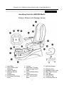
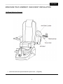
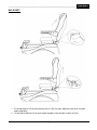
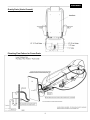
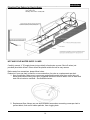
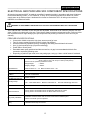
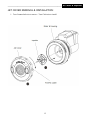
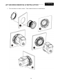
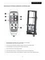
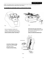
Pioneering “Smart” Pedi-Spas PEDICURE SPA USER MANUAL LIBERTE Before Operating the unit, please read this manual thoroughly and retain it for future reference. RECEIVING AND INSPECTION: PLEASE TAKE NOTE! Thoroughly inspect each shipment immediately upon arrival. It is important that you notify the driver and insist on a notation of the damage. Make this notation directly on the freight company’s waybill or bill of lading. Failure to note damage on the waybill or bill of lading may impede and/or prevent any claims that you may have against the freight carrier. If missing parts or damage is found. Please notify the carrier at once and request an inspection. DO NOT DISCARD THE SHIPPING BOX. If you give the carrier a clear receipt for goods that have been damaged in transit, you do so at your own risk and expense. TRADEMARK DISCLAIMER V-Spa, Elite Platinum, Mystique, Versas, Vista, Elite Ultra, Q-Spa, Sani-Drain, PureFlo, Pioneering “SMART” Pedi-Spa, Auto-Fill, AutoClean, and TT350 and Tru-Touch are the registered trademarks of Lexor, Inc. Reproduction or reuse of part or all of trademarks are expressly prohibited without written permission from Lexor, Inc. Due to limitation of the printing process, product colors shown might look different from actual colors. Lexor will not be responsible for any misprint of this advertisement. Lexor’s footspa specification and prices may change without prior notice. Pedicure Spas are intended for professional used only, always follow your State Board’s sanitation and disinfectant guideline. Table of Contents RECEIVING AND INSPECTION: .................................................................1 SAFETY PRECAUTIONS: ...........................................................................3 Identifying Parts for LIBERTE® Model .....................................................4 MANICURE TRAY/ ARMREST / BACK REST INSTALLATION ................6 Up/Down Swinging Armrest: .......................................................................................6 BACK REST: ..............................................................................................................7 Plumbing Connections: .............................................................................8 Power Drain: ...............................................................................................................8 Gravity Drain (Under Ground):....................................................................................9 Plumbing Flow Pattern for Power Drain: .....................................................................9 Plumbing Flow Pattern for Gravity Drain:..................................................................10 HOT AND COLD WATER SUPPLY LINES ..............................................................10 ELECTRICAL AND PEDICURE SPA COMPONENT SPECIFICATIONS 12 OPERATION AND CARE INSTRUCTIONS ..............................................13 Auto-Fill™:...............................................................................................................................13 JET COVER REMOVAL & INSTALLATION: ............................................15 JET HOUSING REMOVAL & INSTALLATION .........................................16 MASSAGE SYSTEM & REMOTE CONTROLLER: ..................................17 Safety Requirements for Pedicure Spas ....................................................................................19 2 ________________________________________________________________Safety Precautions READ AND FOLLOW INSTRUCTIONS CAREFULLY SAFETY PRECAUTIONS: Warning THIS PRODUCT IS FOR INDOOR USE ONLY DISCONNECT POWER SUPPLY CORD BEFORE SERVICING This product is to be connected to a branch circuit outlet protected by a Class A GROUND FAULT CIRCUIT INTERRUPTER (GFCI), and the GFCI shall be tested regularly for continued protection and correct operation. If a Class A GFCI protected outlet is not available, DO NOT USE THIS PRODUCT! Please contact a licensed electrician for installation of a Class A GFCI according to local electric codes, or equivalent. Warning DO NOT USE if you are diabetic, have poor circulation, or if any area of your feet or legs is inflamed or has an open sore. Consult your physician before using if you have any kind of fungal infection, swelling, fracture or persistent pain. Warning • • • TO REDUCE RISK OF INJURY, DO NOT PERMIT CHILDREN TO USE THIS UNIT UNLESS THEY ARE CLOSELY SUPPERVISED AT ALL TIME LIRE LES INSTRUCTION DU FABRICANT AVANT DE METTRE EN MARCHE UTILISER SEULEMENT A L’INTERIEUR COUPER LE COURANT AVANT DE PROCEDRE AU DEPANNAGE, AU NETTOYAGE Warning 1. Excessive water temperature is dangerous and should be checked BEFORE use. 2. Maximum temperature of the water should never exceed 100 degrees F. 3. DO NOT STEP/ STAND IN FOOT BASIN. 4. Always enter and exit the Pedicure Spa slowly and carefully. 5. NEVER bring and / or operate any electrical devices into or near the Pedicure Spa. 6. Maximum load in spa chair is 250lbs (114kg). Warning If a crack in the GLASS BOWL occurs, DO NOT handle unless the proper attire and equipment is used. Discontinue use of the bowl until proper equipment is replaced. You may be held accountable for any injury that may occur. Lexor, Inc. is not liable for any injury that may occur. STATES’ NOTICE In the common wealth of most of the States, all pedicure spas shall be installed for Commercial usage in the states, are required to have backflow preventer. This equipment shall be installed between the water inlets and the spa at Salon’s cost. 3 PLEASE SAVE THESE INSTRUCTIONS FOR FUTURE REFERENCE ________________________________________________________ Identifying Parts Identifying Parts for LIBERTE® Model Pedicure Whirlpool with Massage System 1. Head Rest 2. Chair Cushion with Massage 3. Armrest Cushion 4. Massage Remote Control 5. Angelic Bowl 6. Flex Water Filler/Spray Spout 7. Footrest 8. Sani-Drain™ System with discharge On/Off Knob 9. Hot/Cold Water Mixer Valve 10. Dual Function AutoFill™ & Jet On/Off Knob 4 11. Up/Down Armrest 12. Manicure-Tray 13. Handbag (Purse) Hook 14. Water Level Sensors 15. Tub Light 16. Drain Stopper 17. Pure-Flo™ Jet 18. Low Profile Stool for Pedicure ________________________________________________________________ Installation SPA to SPA RECOMMENDED CLEARANCE: Wall Clearance: 5 ________________________________________________________________ Installation MANICURE TRAY/ ARMREST / BACK REST INSTALLATION Up/Down Swinging Armrest: 1. Insert the manicure trays and attach the purse hook. (1 Supplied) 6 ________________________________________________________________ Installation BACK REST: 1. To set backrest up: Lift up the backrest until a “Click” is heard. Make sure the lever is locked before operating. 2. To fold down backrest: Lift up lever handle located on the left side / bottom of Chair. 7 _______________________________________________________________ Installation Plumbing Connections: Warning Before any connection, pay attention to these subjects: 1. Debris or residue may become lodged into the Hot and Cold hoses during construction, which may clog the Hot and Cold Mixer. To clean, drain a good amount of water from water hoses to bucket before connecting them to the pedicure spa. Failure to do so may void your Warranty. 2. Hooking up a used Hot/Cold flex hose is not recommended since debris from broken rubber seal might clog water mixer. Failure to do so may void your Warranty. 3. Backflow preventer: Due to differences in construction lay-out of your Salon and City’s plumbing code, please contact your local Plumber to fulfill your needs as required. Backflow Preventers are not supplied by the pedicure spa manufacturer. 4. Check valve is an optional part and supplied free of charge for your convenience. Factory is not liable for this Check valve. 5. Maximum Inlet water pressure must be under 75 PSI. Power Drain: 8 _______________________________________________________________ Installation Gravity Drain (Under Ground): Plumbing Flow Pattern for Power Drain: 9 _______________________________________________________________Installation Plumbing Flow Pattern for Gravity Drain: HOT AND COLD WATER SUPPLY LINES Carefully connect ½” ID supply hoses (not provided) to fresh water sources. Shut-off valves (not provided) should be utilized. Valves should be placed outside the tub for easy access. Before water line connections, please follow below: Determine if your spa chair is used for a new construction of a salon or a replacement spa chair. 1. New construction: Make sure to remove any and all debris and/or dust from current hot cold water pipes before hooking up to spa. Suggested direction to remove debris: turn on water and drain into a bucket or container. See illustration below: 2. Replacement Spa: Always use new hot/cold water hoses when connecting a new spa chair to prevent debris, such as old rubber particles, from clogging drain. 10 _________________________________________________________________Installation CONNECT DRAIN WITH POWER DRAIN (PUMP) Using ¾” schedule 40 PVC (Power Drain) and appropriate traps. Connect drain to meet local plumbing codes. Rubber connection to the drain should be removable for easy service and should not be permanent to prevent damages. 11 ______________________________________________________ Spa Specifications ELECTRICAL AND PEDICURE SPA COMPONENT SPECIFICATIONS All electrical connections MUST be made by a qualified, licensed electrician in accordance with Local & National Electrical and Building Codes. A 110V-50/60 Hz, 15 Amp, GFCI protected grounded circuit MUST be used to supply power to the Pedicure Spa. A dedicated circuit must be used with a GFCI. All wiring must conform to National & Local Electrical Codes. WARNING: IT IS EXTREMELY IMPORTANT THAT THE FOOT SPA OPERATES WITH GFCI PROTECTION VERY IMPORTANT Both back of chair and seat are adjustable. When both are at maximum positions one must allow 18”(44cm) from back wall to foot spa. This minimum distance assures unobstructed recline. Failure to follow this required dimension might damage your spa components and plumbing connections, which will void your warranty. PEDICURE SPA SPECIFICATIONS: • • • • • • • Construction: Marble composite, high gloss, acetone-proof gel coat. Two (2) electro-mechanical knobs control the drain and whirlpool. Electro-mechanically operated reclining, massaging, and sliding seat with hand held control. One (1) pipe-less whirlpool jet. (Pipe-free technology) Power drain or Gravity drain Extendable water spray positioned well above water line, air gap is accommodated with back-flow prevention required by plumbing code Depending on pedicure spa model, arms may swing open, swing up / down or slide forward / backward. SPECIFICATIONS Spa Dimensions & Weights Adjustable Stool Spa Water Capacity All Spa (seat up-right): L≈51”-52”(129-132cm), Versas® model Length = 50” (127cm) W=31”(79cm) w/ Tray ≈45”-46”(114-116cm) H=56”(142cm) *Clearance of 18” (20.32cm) needed for recline Empty Weight: ~ 200 lbs. Shipping Weight: ~ 260 lbs. Pedicure Stool: 12” – 13”. Manicure Stool: 16.25” – 20” ~ 5 US Gallon Jet Motor 120 VAC. at 85W 60Hz Massage Motors, Seat Sliding & Reclining 24VDC, 2.5A x 5 Discharge Pump Motor – 120V at 85W 60 Hz Maximum vertical lift: 3ft . Flow rate 500 GPH @ floor level Power source 115 VAC, 60HZ. Power needed per spa chair = 6 Amp Electrical Switches One (1) electro-mechanical knob for the Whirlpool. Rated at 5A contact. One (1) electro-mechanical knob for the Drain. Rated at 5A contact. Plug & Play Installation Installation should be made with connection at the external interface parts. Please consult with your local plumber. Safety Liberte® Pedicure Spa is UL listed. 12 _______________________________________________________ Operation and Care OPERATION AND CARE INSTRUCTIONS Auto-Fill™: Automatic Auto-Fill™ cycle: Water will automatically turn-off when optimal water level is detected by 2 sensors It is followed with the immediate start of Whirlpool jet for a duty cycle of thirty (30) minutes. The Auto-Fill™ cycle is safely protected by 2 sensors, 3-minute time out and can be extended with a manually operative shut-off valve located at the front panel. Please note: The 3-minute time out is designed for overflow protection in case of an emergency. If water flow rate is too weak due to current plumbing, you may notice the water stops before reaching water sensor. This is because the 3-minute time out has been activated. To continue filling, turn the Auto-Fill knob clockwise. Important! Must scrub and clean water sensors frequently to ensure that water stops right at sensor level. If necessary, clean using sponge buffer. Manual conversion: Auto-Fill™ option can be simply reset to normal manual mode as a contingent system when automatic operation becomes unavailable. Please call our Customer care for step by step instructions. Panel Functional Switches & Operating Instructions: Hot/Cold water faucet located at the center of the front panel. 1.1 Use faucet knob to adjust optimal water temperature at “H” (Left) or “C” (Right) directory. 1.2 Pull out and tilt down faucet knob to shut off water any time during the automatic or manual operational cycle. Warning Must be used when spa chair is left unattended or for overnight procedures to shut off water supply to basin. 13 _______________________________________________________ Operation and Care Auto-Fill™ / Jet Switch: (Dual-functional momentary switch located on the right side of the front panel) 1. To turn water on: Turn knob clockwise for 1 second and release. Water will fill up to reach the sensor level and activate the whirlpool jets to proceed a running duration of thirty (30) minutes automatically. 2. To turn water off: Turn knob clockwise for 1 second and release to turn off water. The switch can be activated to turn on or turn off water any time during the Auto-Fill™ cycle, EXCEPT when water is at sensor level. 3. To turn On / Off the whirlpool jet: Turn knob clockwise for 1 second and release. This Jet cannot be turned on if water level is not at sensor level. Drain Switch: (Dual Action Electro-mechanical Switch located on the left side of the front panel) When activating the switch, it will raise the drain-stopper and power up the drain pump (if exist) at the same time. 3.1 To drain water: Turn the drain knob clockwise. Switch is activated. 3.2 To turn off the drain pump: Turn the drain knob counterclockwise. 14 _______________________________________________________ Jet Cover & Impeller JET COVER REMOVAL & INSTALLATION: 1. Turn Counterclockwise to remove. Turn Clockwise to install. 15 _______________________________________________________ Jet Housing JET HOUSING REMOVAL & INSTALLATION 1. Turn clockwise to remove motor. Turn counterclockwise to install motor. 16 ______________________________________________________________ Operation and Care MASSAGE SYSTEM & REMOTE CONTROLLER: 1. Press Auto Button to start Auto mode. Press again to turn off massage. Auto and Manual mode will run for duration of 15min. 2. Press any button (Rolling/Spot, Kneading, Tapping, Combine) to enter Manual mode. 3. Press Rolling/Spot to stop rolling up/down and stop at desired spot. 4. Press Intensity button to select tapping intensity. 5. Vibro Button/LED is an option. Pressing this button will resume with Tapping action. 6. Press any chair button (Recline, Incline, Backward, Forward) to move the chair to desired positions. 17 _______________________________________________________ Operation and Care NOTE : If the Massage Chair is not provided, then the end-user will need to install a UL listed and cUL/CSA certified massage chair with a suitable Class 2 Power Supply. TOP MASSAGE CHAIR BASIC INSTALLATION INSTRUCTIONS: Fig.2 Fig.1 Install seat cushion with 2 screw-Knobs Lever the back massage and secure 2 hinge screws onto the metal brackets.(Do not turn the screws all the way in ) Leave 1/4” thread screw head for sliding Install back shell with 4 screws as Fig.3 Drill 4 mounting holes ½”.Width=16.5” Length=11 .Install seat frame and secure 4 screws from bottom base.Using the provided stand-off to adjust the height of seat frame as needed to allow seat frame to travel freely. . Controller PCB Lift up back massage to engage locking device. (Manually adjust actuator rod to lock as needed) Install back cushions. Plug AC cord to power strip Located inside of the tub base. Fig.3 18 WARNING You must always refer to your state or local guidelines for cleaning requirements. Overnight soaking with overdosed Chlorine may damage rubber part in basin CLEANING PROCEDURE IS REQUIRED BY STATE BOARDS Note: *** A cleaning log should be kept with each pedicure spa *** Each State will have slight differences in cleaning policies, please check with your state’s Bureau of Barbering and Cosmetology or Regulatory Authority for specific details. Safety Requirements for Pedicure Spas The Bureau of Barbering and Cosmetology requires that salons using whirlpool pedicure foot spas must follow these disinfecting procedures to ensure proper cleaning and maintenance of the equipment and to prevent the spread of bacterial or parasitic disease. Violation of this section may result on an administrative fine and/or disciplinary action. Each foot spa that is not in compliance with this section may result in a separate violation. NOTE: Authority cited: Section 7312, Business and Profession Code. Reference: Section 7312 (e), Business and Professsion Code. Below is a suggestion for your pedicure spa chair’s cleaning procedure: After Each Customer 1. All water shall be drained and all debris shall be removed from the spa basin. 2. The spa basin must be cleaned with soap or detergent and water 3. The spa basin must be disinfected with an EPA-registered disinfectant with demonstrated bactericidal, fungicidal, and virucidal activity, which must be used according to manufacturer’s instructions. 4. The spa basin must be wiped dry with a clean towel. At the End of Each Day 1. The screen shall be removed, all debris trapped behind the screen shall be removed, and the screen and the inlet shall be washed with soap or detergent and water. 2. Before replacing the screen, the screen shall be totally immersed in an EPA-registered disinfected with demonstrated bactericidal, fungicidal and virucidal activity, which must be used according to the manufacturer’s instructions. 3. The spa system shall be flushed with low sudding soap and warm for at least 10 minutes, after which the spa shall be rinsed and drained. At Least Once A Week 1. The spa basin shall be filled completely with warm water and 1 teaspoon of 5.25% bleach for each gallon of water, or a solution of Sodium Hypochlorite of approximately 50ppm used according to manufacturer’s instructions. 2. The spa system shall be flushed with the bleach and water solution, or Sodium Hypochlorite solution, for 5-10 minutes and allowed to sit for 6-10 hours. 3. The spa system shall be drained and flushed with water before use upon a patron. 19 WARNING PROPER INSTALLATION ACCORDING TO THIS MANUAL IS REQUIRED. FAILURE TO DO SO MAY RESULT IN SERIOUS INJURY AND/OR WARRANTY WILL BE NULL. YOU MUST HAVE A QUALIFIED LICENSED PLUMBER TO CONNECT THE SPA IN PLACE SAFELY. UL SAFETY RECOGNIZED FOR UNITED STATES AND CANADA. ©2012 All Rights reserved. Design and Specifications are subject to change without notice V3.0 20