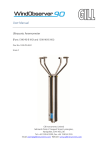
1
WindSonic
Doc No 1405 PS 0019 Issue 15
WindSonic
User Manual
Doc No. 1405-PS-0019
Issue 15
Gill Instruments Limited
Saltmarsh Park,
67 Gosport Street,
Lymington,
Hampshire.
SO41 9EG
UK
Tel: +44 (0) 1590 613500
Fax: +44 (0) 1590 613501
E-mail: [email protected]
Website: www.gill.co.uk
1
August 2006
WindSonic
Doc No 1405 PS 0019 Issue 15
August 2006
Contents
1
2
3
4
5
6
FOREWORD ................................................................................................................ 4
INTRODUCTION ........................................................................................................ 4
FAST TRACK SET-UP................................................................................................ 4
PRINCIPLE OF OPERATION ................................................................................... 5
SPECIFICATION......................................................................................................... 7
PRE-INSTALLATION................................................................................................. 9
6.1
EQUIPMENT SUPPLIED ............................................................................................... 9
6.2
PACKAGING.............................................................................................................. 9
6.3
INSTALLATION REQUIREMENTS ............................................................................... 10
6.4
CABLE ASSEMBLY .................................................................................................. 11
6.5
WINDCOM ............................................................................................................. 14
7
INSTALLATION........................................................................................................ 15
7.1
INSTALLATION GUIDELINES .................................................................................... 15
7.2
BENCH SYSTEM TEST .............................................................................................. 16
7.3
ELECTRICAL ........................................................................................................... 16
Cable............................................................................................................................. 16
Power supply ................................................................................................................ 17
Configuring Hyperterminal .......................................................................................... 18
Auto Mode..................................................................................................................... 18
Connecting to a PC using RS232 (Options 1, 2 or 3) ................................................... 19
Connecting to a Gill WindDisplay ................................................................................ 20
Connecting to a PC using RS422 (Option 2 or 3)......................................................... 21
Networking using RS485 (Option 2 or 3)...................................................................... 22
Using the Analogue Output (Option 3) ......................................................................... 23
Connecting to an SDI-12 Interface (Option 4).............................................................. 24
7.4
MECHANICAL ......................................................................................................... 25
Orientation.................................................................................................................... 25
Alignment...................................................................................................................... 25
Mounting....................................................................................................................... 25
8
USING WITH THE GILL WindDisplay .................................................................. 27
9
MESSAGE FORMATS .............................................................................................. 28
9.1
GILL FORMAT– POLAR, CONTINUOUS (DEFAULT FORMAT) ..................................... 28
9.2
GILL FORMAT – UV, CONTINUOUS ......................................................................... 30
9.3
GILL FORMAT – POLLED (POLAR OR UV)............................................................... 31
9.4
NMEA FORMAT .................................................................................................... 31
9.5
ANALOGUE OUTPUTS AND OPTIONS ......................................................................... 32
10
CONFIGURING ..................................................................................................... 34
10.1
ENTERING CONFIGURATION MODE ...................................................................... 34
10.2
RETURNING TO MEASUREMENT MODE ................................................................ 34
10.3
CHECKING THE CONFIGURATION ......................................................................... 34
10.4
CHANGING A SETTING ......................................................................................... 35
10.5
MEASUREMENT SETTINGS ................................................................................... 35
10.6
OUTPUT UNITS ................................................................................................... 35
2
WindSonic
Doc No 1405 PS 0019 Issue 15
August 2006
10.7
ASCII OUTPUT FORMAT ..................................................................................... 35
10.8
MESSAGE TERMINATOR ...................................................................................... 36
10.9
OUTPUT RATE .................................................................................................... 36
10.10
BAUD RATE ........................................................................................................ 36
10.11
DATA AND PARITY OPTIONS ................................................................................ 36
10.12
POWER-UP MESSAGE .......................................................................................... 37
10.13
NODE ADDRESS .................................................................................................. 37
10.14
COMMUNICATIONS PROTOCOL ............................................................................ 37
10.15
ANALOGUE SETTINGS ......................................................................................... 38
Polar mode direction calculation.................................................................................. 38
Magnitude scaling......................................................................................................... 38
Error conditions............................................................................................................ 39
Disabled outputs ........................................................................................................... 39
10.16
CONFIGURATION / DIAGNOSTIC INFORMATION.................................................... 39
11
SDI-12 COMMANDS ............................................................................................. 40
12
MAINTENANCE & FAULT-FINDING ........................................................ 42
12.1
CLEANING .......................................................................................................... 42
12.2
SERVICING ......................................................................................................... 42
12.3
FAULT FINDING .................................................................................................. 42
12.4
RETURNING UNIT ............................................................................................... 43
12.5
STATUS .............................................................................................................. 43
13
TESTS...................................................................................................................... 44
13.1
BENCH TEST ....................................................................................................... 44
13.2
SELF-TEST (STILL AIR) ...................................................................................... 45
13.3
CALIBRATION ..................................................................................................... 46
14
APPENDICES ......................................................................................................... 47
14.1
GLOSSARY & ABBREVIATIONS ........................................................................... 47
14.2
GUARANTEE ....................................................................................................... 47
14.3
ELECTRICAL CONFORMITY ................................................................................. 48
3
WindSonic
Doc No 1405 PS 0019 Issue 15
August 2006
WindSonic
Doc No 1405 PS 0019 Issue 15
August 2006
4 PRINCIPLE OF OPERATION
1 FOREWORD
Thank you for purchasing the WindSonic manufactured by Gill Instruments Ltd. The unit
has no customer serviceable parts and requires no calibration or maintenance. To achieve
optimum performance we recommend that you read the whole of this manual before
proceeding with use. Do NOT remove black “rubber” transducer caps.
Gill products are in continuous development and therefore specifications may be subject to
change and design improvements without prior notice.
The information contained in this manual remains the property of Gill Instruments and
should not be copied or reproduced for commercial gain.
The WindSonic measures the times taken for an ultrasonic pulse of sound to travel from the
North transducer to the South transducer, and compares it with the time for a pulse to travel
from S to N transducer. Likewise times are compared between West and East, and E and W
transducer.
If, for example, a North wind is blowing, then the time taken for the pulse to travel from N
to S will be faster than from S to N, whereas the W to E, and E to W times will be the same.
The wind speed and direction can then be calculated from the differences in the times of
flight on each axis. This calculation is independent of factors such as temperature.
2 INTRODUCTION
The Gill WindSonic wind sensor is a very robust, lightweight unit with no moving parts,
outputting wind speed and direction. The units of wind speed, output rate and formats are all
user selectable.
The WindSonic can be used in conjunction with a PC, datalogger or other device, provided it
is compatible with one of the standard communication formats provided by the WindSonic.
WindSonic (option 2 or 3 only) is designed to connect directly to the Gill WindDisplay unit
to provide a complete wind speed direction system without any configuration by the user.
WindSonic (options 1, 2 and 3) may be configured using WindCom software which is
available, free of charge, from the Gill website www.gill.co.uk.
WindSonic (option 4) SDI-12 may not be re-configured in any Gill output format.
The output message format can be configured in Gill format, in Polar or UV (2-axis) format,
and to either Polled (requested by host system) or Continuous output. Alternatively, it can be
configured in NMEA (0183 Version 3) or SDI-12 (V1.3). These are described in Section 9
MESSAGE FORMATS and Section 11 SDI-12 COMMANDS.
3 FAST TRACK SET-UP
If you are in a hurry to try out the WindSonic (options 1, 2 or 3) and are familiar with Gill
equipment and coupling to a PC using RS232, go to the following sections :
Section 7 INSTALLATION
Section 9 MESSAGE FORMATS
Section 10 CONFIGURING
After you have successfully set up the WindSonic, we strongly advise that you then go back
and read the rest of the manual to ensure that you get the best results from the WindSonic.
Figure 1 Time of Flight details
4
5
WindSonic
Doc No 1405 PS 0019 Issue 15
August 2006
WindSonic
Doc No 1405 PS 0019 Issue 15
August 2006
5 SPECIFICATION
Output
Units of measure
Output frequency
Parameters
or
Wind Speed
Range
Accuracy
Resolution
Wind Direction
Range
Accuracy
Resolution
Analogue output
formats
0-5V
4-20mA
Digital output
formats
Gill
Figure 2 Compass Points
Marine – NMEA
Data Logger
Communication
formats
WindSonic Option 1
WindSonic Option 2
WindSonic Option 3
WindSonic Option 4
Anemometer status
Environmental
Moisture protection
Temperature
Humidity
EMC
Standards
6
Metres/second (m/s),
Knots, Miles per hour (mph),
Kilometres per hour (kph),
Feet per minute (fpm)
1, 2, or 4 outputs per second
Digital
Analogue
Polar - Speed and Direction Polar - Speed and Direction
UV - 2 axis, signed Speed
Tunnel - U Speed and U Direction
0 – 5m/s, 0 – 10m/s, 0 – 20m/s,
0 – 60 m/s
0 – 30m/s, 0 – 50m/s, 0 – 60m/s,
± 2% (at 12m/s)
± 2% (at 12m/s)
0.01 m/s
0.01 m/s
0 - 359°
or 0 - 539° (Wraparound mode)
±3° (at 20m/s)
1°
0 - 359°
± 3° (20m/s)
1°
± 1% of full scale N.B. Analogue output impedance = 1KΩ
Continuous or Polled (output on request by host system)
Polar (Speed and Direction ) or UV (2 axis, signed Speed)
NMEA 0183 version 3
SDI-12 V1.3
RS232
RS232, RS422, RS485
RS232, RS422, RS485, and Analogue (0 – 5V or 4 – 20mA)
SDI-12
Note: WindSonic Option 4 is not compatible with WindCom
Status OK and Error codes included as part of standard output
message
IP65
Operating -35°C to +70°C Storage -40°C to +80°C
Operating <5% to 100%
EN 61000-6 - 3 (Emissions)
EN 61000-6 - 2 (Immunity)
Manufactured within ISO9001: 2000 quality system
7
WindSonic
Power requirement
Mechanical
Size / weight
Mounting
Material
Doc No 1405 PS 0019 Issue 15
August 2006
9 – 30 V DC. Current drain depends on variant i.e. RS232
approximately 14mA rising to 44mA for Analogue variant.
142mm diameter x 160mm
0.5kg
Pipe mounting 1.75 inches (44.45mm) diameter
External - Acrylate Styrene Acrylonitrile, Polycarbonate blend.
WindSonic
Doc No 1405 PS 0019 Issue 15
August 2006
6 PRE-INSTALLATION
6.1
Equipment supplied
Item
Quantity
WindSonic
1
Connector assembly comprising
9 Way connector
Contacts
Sealing Gland
Washer
Washer shake proof
Screws – M5 stainless steel
User Manual
1
9
1
1
4
4
1
WindCom software is available free of charge from the Gill website – www.gill.co.uk
NOTE:
WindSonic Option 1 – RS 232 output only
WindSonic Option 2 – RS 232, 422 & 485 output
WindSonic Option 3 – RS 232, 422, 485 & analogue output
WindSonic Option 4 – SDI-12
Optional extras:
Item
Part No
Cable 4 Pair (Option 3 & 4 WindSonic)
026-03156
Cable 3 Pair (Option 1 & 2 WindSonic)
026-02660
WindSonic connector (1 supplied as standard see above)
1405-PK-050
WindSonic Support Tube
1405-30-056
6.2
Packaging
Whilst the WindSonic is being moved to its installation site, the unit should be kept in its
inner packaging. All the packaging should be retained for use if the unit has to be returned at
any time, or if a self test is performed.
8
9
WindSonic
6.3
Doc No 1405 PS 0019 Issue 15
August 2006
Installation requirements
Host system - One of the following:
PC fitted with a suitable interface to match the chosen communication format
(RS232, RS422, or RS485), compatible with the WindSonic option selected,
and a suitable Terminal Emulation software package. (For example
Hyperterminal for Windows™ 9x, Windows™ 2000 and XP or Terminal for
Windows™ 3.n will normally be available on your PC.) WindCom is
available from the Gill website.
Gill WindDisplay (WindSonic option 2 or 3 only)
Other equipment with input/output compatibility to the WindSonic Option
selected.
For example, Chart recorder or Data logger, using the WindSonic Analogue
output or SDI-12 output.
Cable
- To connect between the WindSonic and the host system
See Section 7.3 Cable type for cable specification.
There are restrictions on the maximum cable lengths for correct operation.
The cable should be routed up the inside of the mounting tube.
WindSonic
6.4
Doc No 1405 PS 0019 Issue 15
Cable Assembly
Open the pack of parts provided with the WindSonic or as 1405-PK-050
Strip the cable and solder the contact pins to the cores (please note that the connector
supplies the correct strain relief for cables with an outside diameter of 6-12mm).
Put the parts on the cable in the order as shown below.
Whilst squeezing the red retainer in the direction of ARROWS A, pull in the direction of
ARROW B.
A
A
Mounting tube
Standard tube 1.75 inches (44.45mm) Outside Diameter x 3mm wall
thickness
See Figure 3 in section 7.4 Alignment & Mounting Details
For non-hostile environments, Aluminium tube can be used.
For hostile environments, you should select a material suitable for the
intended environment. For example, stainless steel 316 for marine use.
B
Your connector should now resemble the connector in the picture below.
10
August 2006
11
WindSonic
Doc No 1405 PS 0019 Issue 15
August 2006
Insert each contact pin until you feel a slight click. If you have inserted the contact into the
incorrect hole it can be removed at this point by simply pulling it out. Please note there will
be some resistance.
WindSonic
Doc No 1405 PS 0019 Issue 15
August 2006
Continue to insert all of the contacts you require. Once all of the contacts are inserted push
the red retainer into place. NB. The retainer can only be pushed back into place if the
contacts are fully engaged.
Fit the connector to the WindSonic so that you can finish assembling the connector.
Rear View of Connector
1
8
7
2
9
Screw the backshell onto the connector until it is fully in place. Please note that the final
rotations can be slightly stiff.
3
4
6
5
12
13
WindSonic
Doc No 1405 PS 0019 Issue 15
August 2006
Now screw the next part of the connector into place.
WindSonic
Doc No 1405 PS 0019 Issue 15
August 2006
7 INSTALLATION
Do NOT remove the black “rubber” transducer caps. Warranty is void if the coloured
security seal is damaged or removed.
7.1
Installation Guidelines
The WindSonic has been designed to meet and exceed the stringent standards listed in its
specification. Operating in diverse environments all over the world, WindSonic requires no
calibration and adjustment whatsoever.
Now screw the cable-clamping nut into place.
As with any sophisticated electronics, good engineering practice should be followed to
ensure correct operation.
•
Always check the installation to ensure the WindSonic is not affected by other
equipment operating locally, which may not conform to current standards, e.g.
radio/radar transmitters, boat engines, generators etc.
Guidelines –
o Avoid mounting in the plane of any radar scanner – a vertical separation
of at least 2m should be achieved.
o Radio transmitting antennas, the following minimum separations (all
round) are suggested
VHF IMM – 1m
MF/HF – 5m
Satcom – 5m (avoid likely lines of sight)
•
Use cables recommended by Gill. If cables are cut and re-connected incorrectly
(perhaps in a junction box) then EMC performance may be compromised if cable
screen integrity is not maintained.
•
Earth loops should not be created – wire the system in accordance with the
installation guidelines.
The connector can now be removed from the WindSonic.
NOTE: To disassemble the connector, reverse this procedure.
6.5
WindCom
WindCom is available for the customer to download, free of charge, from the Gill
Instruments Ltd website www.gill.co.uk.
WindCom features include:
•
Data Display
•
Data Logging
•
Wind Alarms
•
Avoid turbulence caused by surrounding structures that will affect the accuracy of the
WindSonic such as trees, masts and buildings. The WMO make the following
recommendations:
•
NOTE: WindCom is not compatible with WindSonic Option 4 – SDI-12.
14
Ensure the power supply operates to the WindSonic specification at all times.
The standard exposure of wind instruments over level open terrain is 10m above the
ground. Open terrain is defined as an area where the distance between the sensor and
any obstruction is at least 10 times the height of the obstruction.
15
WindSonic
7.2
Doc No 1405 PS 0019 Issue 15
August 2006
Bench system test
Doc No 1405 PS 0019 Issue 15
August 2006
Cable length
Note : Prior to physically mounting the WindSonic in its final location, we
strongly recommend that a bench system test is carried out to confirm the
system is configured correctly, is fully functional and electrically
compatible with the selected host system and cabling (preferably utilising
the final cable length). The required data format, units, output rate, and
other options should also all be set up at this stage.
7.3
WindSonic
The maximum cable length is dependent on the chosen communication format (RS232,
RS422 or RS485), the baud rate, and, to a lesser extent, on the cable type and the local
electrical ‘noise’ level.
The table shows the typical maximum lengths at the given baud rates, using the
recommended cable. If any problems of data corruption etc are experienced, then a slower
baud rate should be used. Alternatively, a thicker or higher specification cable can be tried.
WindSonic
Option
Electrical
Cable
Cable type
A RS422 compatible cable should be used, with the number of twisted pairs matching the
application.
Communication format
RS232
9600
6.5 m (20 ft)
Option 2
RS422/485
9600
1 km (3200 ft)
Option 3
Analogue – Voltage o/p
N/A
6.5 m (20 ft)
Analogue – Current o/p
N/A
Resistance dependent
(max 300 Ω)
SDI-12
1200
90m (300ft)
Option 4
The table shows some suitable manufacturers’ references; other manufacturers’ equivalents
can be used.
Power supply
No. of pairs
Gill ref.
WindDisplay
2
-
RS 232
3
RS 422/485
4
SDI-12
2
Belden ref.
Batt
electronics
ref.
9729
-
026-02660
9730
91030
026-03156
9728
91199
9729
-
-
16
Max. cable length
Option 1
Generic description – Twisted pairs with drain wire, screened with aluminised tape,
with an overall PVC sheath. Wire size 7/0.2mm (24 AWG)
Application
Baud rate
The WindSonic requires a DC supply of between 9 – 30 V DC. Current drain depends on
variant i.e. RS232 approximately 14mA rising to 44mA for Analogue variant.
Note that the relative polarity of the connection of the DC supply to the WindSonic can be
reversed. This is used for options 2 & 3, when the unit is configured in AUTO mode, to
select the communication format.
See Section 10 Configuring
17
WindSonic
Doc No 1405 PS 0019 Issue 15
August 2006
Configuring Hyperterminal
1.
2.
3.
4.
5.
6.
WindSonic
August 2006
Connecting to a PC using RS232 (Options 1, 2 or 3)
Note – Other terminal emulators are configured in a very similar way.
Decide on an available Com port that you want to use (Usually Com1).
Run Hypertrm.exe (Typically accessed via Start Programs Accessories
Hyperterminal)
Create a New Connection (File New Connection)
Enter a Name (eg WindSonic 1) .
Change ‘Connect Using’ to ‘Direct to Com 1’ (or other Com port as required)
Adjust the Port settings to match WindSonic settings. WindSonic default settings are :
Bits per second 9600
Data bits 8
Parity None
Stop bits 1
Flow Control (Handshaking) None
Notes
1. Some PCs have a Serial RS232 interface and a suitable terminal emulation package
already installed, which can easily be utilised with the WindSonic. (Hyperterminal for
Windows™ 9x, Windows™ 2000 and XP or Terminal for Windows™ 3.n)
2. The cable length for reliable operation is limited to 6.5m (20ft).
( See Section 7.3 Cable length.)
3. For longer cable runs, we recommend using the WindSonic configured with RS422
output, and a RS422/232 converter at the PC. See Connecting to a PC using RS422.
WindSonic
PC
9 Way circular connector
Typical 9 Way ‘D’ Connector
Example of message format:
Q, 229, 002.74, M, 00,
Doc No 1405 PS 0019 Issue 15
06
See Section 10 Configuring if you need to change WindSonic settings.
Auto Mode
WindSonic (options 1, 2 and 3) are factory configured in Auto Mode (E1). This facility
enables the customer to select RS232 or RS422/RS485 output when available by changing
the wiring on the mating connector, see the following sections for further details.
WindSonic option 4 SDI-12 is factory configured in SDI-12 mode, see Section 11 SDI-12
Commands for details.
Signal names
Pin nos.
Cable – 3 twisted
pairs
Signal names
Pin nos
TXD
5
RXD
2
RXD
7
TXD
3
Signal
Ground
1
Signal Ground
5
Do NOT
connect
at this end
N/A
Chassis
ground
N/A
V supply
2
Screen and drain
wires
–
DC Power supply
9 – 30V
V supply
3
+
NOTE: Options 2 and 3 only reverse the polarity of the DC power supply to select RS422
output.
18
19
WindSonic
Doc No 1405 PS 0019 Issue 15
August 2006
WindSonic
Doc No 1405 PS 0019 Issue 15
August 2006
Connecting to a PC using RS422 (Option 2 or 3)
Connecting to a Gill WindDisplay
WindSonic
For further details see Section 8 USING WITH THE GILL WINDDISPLAY,
and the WindDisplay User Manual for the method of operation.
Notes
1.
2.
3.
WindSonic Option 2 or 3 must be used.
Use the WindSonic in the factory default mode – i.e. do not reconfigure.
The WindDisplay can provide power to the WindSonic
WindSonic
9 Way circular connector
Signal names
Pin nos.
TXD +
TXD –
4
5
Do NOT connect
at this end
N/A
V supply
2
V supply
3
WindDisplay
Cable – 2 twisted pairs
Screen and drain wires
Signal
names
Terminal
nos.
TXD +
TXD –
8
7
Ground (Earth)
+
O
Default Settings
The WindSonic is factory configured with the following default settings:
M2, U1, O1, L1, P1, B3, F1, H1, NQ, E3
See Section 10 Configuring for further details
20
PC with RS422/232
converter
9 Way circular connector
Signal names
Pin nos.
Cable – 4 twisted pairs
Signal names
TXD+
4
RXD +
TXD –
5
RXD –
RXD+
6
TXD +
RXD –
7
TXD –
Signal Ground
1
Signal Ground
Do NOT connect
at this end
N/A
V supply
2
+
V supply
3
–
Screen and drain wires
Chassis ground
2
1
Configure the terminal emulator as previously described.
See Section 10 Configuring if you need to change WindSonic settings.
21
DC Power
supply
9 – 30V
WindSonic
Doc No 1405 PS 0019 Issue 15
August 2006
WindSonic
Doc No 1405 PS 0019 Issue 15
August 2006
Networking using RS485 (Option 2 or 3)
Using the Analogue Output (Option 3)
Notes
1. Up to 10 WindSonic units can be “daisy chained”.
2. WindSonics must be set in Polled mode, with each device given a unique node address.
See Section 9.1 WindSonic node address.
3. Customers may poll using terminal software (NOT supplied).
Notes
1. If the Current output is used, the total output load MUST be below 300 ohms, including
the cable resistance.
2. The current output loads must be returned to Signal Ground.
3. Reconfiguration of the analogue output requires a digital connection (See sections 9 &
10)
4. In addition, the digital output can be connected if required using RS232, 422 or 485, as
shown in the previous sections.
WindSonic
9 Way circular connector
Signal names
Pin
nos.
TXD+
RXD+
4
6
TXD –
RXD –
PC with RS485 card
Cable – 3 twisted pairs
Signal names
WindSonic
Data logger or
Chart recorder
9 Way circular connector
T/RXD +
Signal names
Pin
nos.
5
7
T/RXD –
Analogue Channel 1
8
Analogue Channel 1
Signal Ground
1
Signal Ground
Analogue Channel 2
9
Analogue Channel 2
Signal Ground
Do NOT connect
at this end
N/A
1
Signal Ground
Do NOT connect
at this end
N/A
V supply
2
+
DC Power supply
V supply
3
–
9 – 30V
V supply
2
+
DC Power supply
V supply
3
–
9 – 30V
Screen and drain wires
Chassis ground
To
Next
Screen and drain wires
Chassis ground
Note: Power supply connections above provide for analogue and RS422 outputs.
Reverse wires on pins 2 and 3 for analogue and RS232 output.
Unit
NOTE: Power needs to be supplied to each unit in the network
NOTE: WINDCOM will not work in polled mode
22
Signal names
Cable – 3 twisted pairs
23
WindSonic
Doc No 1405 PS 0019 Issue 15
August 2006
Connecting to an SDI-12 Interface (Option 4)
WindSonic
7.4
Doc No 1405 PS 0019 Issue 15
August 2006
Mechanical
Before installing, see note at Section 7.2 Bench system test.
Orientation
WindSonic
Data logger or
Chart recorder
9 Way circular connector
Signal names
Pin
nos.
Signal GND
1
V-
3
GND
V+
2
+12V
TXD-
5
RXD-
7
Signal names
Serial Data Line
Normally the WindSonic is mounted on a vertical tube, ensuring a horizontal Measuring
Plane.
See Figure 3 Alignment & Mounting details
For indoor use the unit may be mounted with the Measurement Plane set to any required
orientation.
Alignment
The WindSonic should be aligned to point to North, or any other reference direction –for
example, the bow of a boat.
There are two arrows, a coloured rectangle, and an alignment notch to aid alignment.
See Figure 3 Alignment & Mounting Details
Note : It is usually simpler to work first with a compass at ground level and identify a
suitable landmark and its bearing.
Mounting
The support tube requires three 3 equally spaced holes, tapped M5, 7.5mm from the top of
the tube. Pass the cable (fitted with the 9 way Clipper plug) through the tube.
Note: the customer must fit appropriate strain relief to the cable.
Connect the plug by twisting it whilst pushing it gently into the socket on the WindSonic.
When it locates, twist the outer sleeve clockwise to connect and lock the plug.
Fix the WindSonic to the tube using the 3 stainless steel screws provided. (Maximum
mounting screw torque 4 Nm.)
It is the responsibility of the customer to ensure that the WindSonic is mounted in a position
clear of any structure which may obstruct the airflow or induce turbulence.
Do NOT mount the WindSonic in close proximity of high powered radar or radio
transmitters. A site survey may be required if there is any doubt about the strength of
external electrical noise.
24
25
WindSonic
Doc No 1405 PS 0019 Issue 15
August 2006
WindSonic
Doc No 1405 PS 0019 Issue 15
August 2006
8 USING WITH THE GILL WindDisplay
The WindSonic is designed to link directly to the Gill WindDisplay unit to provide a
complete wind speed and direction system.
After coupling to a WindDisplay, the Wind Speed units and the Averaging period can be
selected using the WindDisplay controls. See the WindDisplay User Manual.
Important :
WindSonic Option 2 or 3 must be used, connected as shown in Section 7.3
Connecting to a Gill WindDisplay.
The WindSonic must be used as supplied, set to the factory default settings.
It must NOT be reconfigured.
Note that although the WindDisplay can display wind speed in various units,
these are calculated within the WindDisplay. The data coming to the
WindDisplay must be in metres/sec (ie the factory default output setting).
Figure 3 Alignment & Mounting details
Figure 4 WindDisplay
26
27
WindSonic
Doc No 1405 PS 0019 Issue 15
August 2006
Doc No 1405 PS 0019 Issue 15
August 2006
WindSonic node address
9 MESSAGE FORMATS
On applying power to the WindSonic, it will provide wind measurements in one of the
following formats:
Gill – Polar, Continuous (default format)
Gill - UV, Continuous
Gill – Polled (Polar or UV)
NMEA
SDI-12 (Polled)
Each of these is described below.
Information on how to change the formats and settings follows in Section 10
CONFIGURING. If you purchased a WindSonic Option 4 SDI-12 refer to Section 11
SDI-12 COMMANDS. Sections 9 and 10 do NOT apply to WindSonic Option 4 SDI-12.
9.1
WindSonic
The default setting is ‘Q’. If there is more than one WindSonic in a network, the others must
be renamed (R to Z), so that each WindSonic is uniquely identified.
Wind direction
Indicated in degrees, from 0 to 359°, with respect to the WindSonic North marker.
In fixed field mode and when the wind speed is below 0.05 metres/sec, the direction will not
be calculated, but the last calculated direction above 0.05 m/s will be output.
Wind speed and units
Shows the Wind Speed in the Measurement Plane (See Figure 3 Alignment & Mounting
details) in one of the following units:
Units
Identifier
Metres per second (default)
Knots
Miles per hour
Kilometres per hour
Feet per minute
Gill format– Polar, Continuous (Default format)
<STX>Q, 229, 002.74, M, 00, <ETX> 16
M
N
P
K
F
Status
WindSonic
node address
Wind
direction
Wind
speed
Units
Status
Check
sum
This indicates either
Where:
or
<STX>
WindSonic node address
Wind direction
Wind speed
Units
Status
=
=
=
=
=
=
<ETX>
Checksum
=
=
Start of string character (ASCII value 2)
Unit identifier
Wind Direction
Wind Speed
Units of measure (knots, m/s etc)
Anemometer status code (see Section 12.5
for further details)
End of string character (ASCII value 3)
This is the EXCLUSIVE – OR of the bytes
between (and not including) the <STX>
and <ETX> characters.
28
Correct operation Code 00
Error codes
See Section 12.5 for explanation of codes.
Checksum
This enables the host system to check that the data has been correctly received. This is the
EXCLUSIVE – OR of the bytes between (and not including) the <STX> and <ETX>
characters.
Output rate (not displayed)
The WindSonic samples continuously and delivers wind information at 1 (default setting), 2,
or 4 outputs / second.
29
WindSonic
9.2
Doc No 1405 PS 0019 Issue 15
August 2006
9.3
Gill format – UV, Continuous
In this mode, the output is given as signed (ie. positive or negative) speeds along the
‘U’ (= South – North) axis and the ‘V’ (= East – West) axis.
<STX>Q, +001.59, - 002.74, M, 00, <ETX> 2D
WindSonic
node
address
U axis
speed and
polarity
V axis
speed and
polarity
Units
Status
Check
sum
Where:
<STX>
WindSonic node address
U axis
V axis
Units
Status
WindSonic
=
=
=
=
=
=
Start of string character (ASCII value 2)
Unit identifier
speed & polarity
speed & polarity
Units of measure ( knots, m/s etc)
Anemometer status code (see Section 12.5
for further details)
<ETX>
=
End of string character (ASCII value 3)
Checksum
=
This is the EXCLUSIVE – OR of the bytes
between (and not including) the <STX>
and <ETX> characters
The WindSonic unit identifier, Units, and Checksum are as described in Section 9.1 above.
Figure 4 shows the polarity of U and V if the wind components along the U and V axis are
blowing in the direction of the respective arrows.
Doc No 1405 PS 0019 Issue 15
Gill format – Polled (Polar or UV)
When in the Polled mode, an output is only generated when the host system sends a Poll
signal to the WindSonic consisting of the WindSonic Unit Identifier – that is, the relevant
letter Q – Z.
The output formats are otherwise as described in Sections 9.1 and 9.2.
The commands available in this mode are :
Description
30
Command
WindSonic Unit Identifier
Q ….. Z
WindSonic response
Wind speed output generated
Enable Polled mode
?
(none)
Disable Polled mode
!
(none)
Request WindSonic Unit Identifier
&
Q ….. Z (as configured)
Enter Configuration mode
*<N>
CONFIGURATION MODE
Where <N> is the unit identifier (See Section 10.13).
9.4
NMEA Format
$ IIMWV, 120, R, 002.10, M, A*5D
Wind direction
Start of
string
Figure 4 UV Polarity
August 2006
Instrument
type
Wind speed
Units
Relative wind measurement
Status
Check sum
The Wind Direction, Wind Speed, and Units are as described in Section 9.1.
The Instrument Type – IIMWV - is a mnemonic for Integrated Instrument Mean Wind
direction & Velocity.
The Status codes are :
A
Valid measurement
V
Invalid measurement
A typical WindSonic configuration suitable for NMEA (See Section 10):
M5, U1, O1, L1, P1, B2, F1, H1, NQ, E1
Consult specification NMEA 0183 version 3 (available on the web) for complete interface
details.
31
WindSonic
9.5
Doc No 1405 PS 0019 Issue 15
August 2006
WindSonic
Doc No 1405 PS 0019 Issue 15
Low wind speeds in polar mode
Analogue outputs and options
Note : Analogue outputs are only available from WindSonic Option 3.
Voltage or Current output
The WindSonic (Option 3) can be configured for either Voltage (0 – 5 V) or Current (4 – 20
mA) outputs.
Important :
1. When using the current outputs, the load resistance between the Analogue outputs (Pins
8 & 9) and Signal Ground must be <= 300 ohms, including cable resistance.
This is to ensure that the voltage levels on Pins 8 & 9 do not exceed 5V.
2. The current outputs must be returned to Signal Ground (Pin 1).
Polar and Tunnel modes
If the WindSonic is configured in Gill Polar mode or NMEA mode, the analogue outputs
will be in Polar mode.
If the WindSonic is configured in Gill UV mode, the analogue outputs will be in ‘Tunnel’
mode.
Analogue outputs
Polar mode
Tunnel mode
Channel 1 (Pin 8)
Channel 2 (Pin 9)
Wind speed
Wind direction
U speed
U direction
Whilst the wind speed is below 0.05 metres/sec, the wind direction will not be calculated.
In CSV mode, the Channel 2 output will switch between 0 and 5V (or 4 and 20mA) at the
output rate selected.
In fixed field mode, the last valid direction will be output until a new value can be
calculated.
Wind Speed scaling
The Wind Speed output can be configured such that full-scale output represents 5, 10, 20,
30, 50 or 60 metres/sec.
In all cases zero Wind Speed is represented by 0V or 4mA.
Tunnel mode
When configured in Tunnel mode, Channel 1 output represents the wind speed along the U
axis (South – North) scaled as described above.
Channel 2 gives the direction of the wind along the U axis, where a –U vector (= wind from
the N direction) is represented by 0V (or 4mA), and a +U vector is represented by 5V (or
20mA).
Polar mode direction wraparound
The Wind Direction in Polar mode can be configured for either Standard (0 - 359°) or
Wraparound (0 - 539°) options. If the Standard mode is used with a chart recorder, large
swings of the recorder pen will be experienced each time the wind direction passes between
0 and 359°. Using the Wraparound mode, when the wind first changes from 0° to 359°, there
will be a step change on the output, but after this first time the output will change smoothly
each time the wind passes through 360°. (Similarly, the first time the wind veers from 539°
to 180°, there will be a step change, after which the output will change smoothly).
Wind direction
(degrees)
Voltage output (V)
Standard
0
180
360
540
0
2.5
5.0
n/a
Wraparound
0
1.67
3.33
5.0
32
August 2006
Current output (mA)
Standard
Wraparound
4.00
12.00
20.00
n/a
4.00
9.33
14.67
20.00
33
WindSonic
Doc No 1405 PS 0019 Issue 15
August 2006
WindSonic
Doc No 1405 PS 0019 Issue 15
August 2006
10 CONFIGURING
10.4 Changing a setting
WindCom may be used to configure WindSonic, alternatively, the user may elect to use
another terminal emulator package.This section describes the commands used to change
User and Communications settings.
To change a setting, refer to the sections below, and enter the command of the new setting
required, followed by ENTER . If successful, the new setting will be sent as a message by
the WindSonic.
For example, to change the message format to NMEA, enter
M 5
ENTER
The WindSonic will reply M5 . When the unit is returned to the Measurement mode, it will
be in NMEA format.
10.1 Entering Configuration mode
From Continuous mode
From Polled mode
* <N>
*
Note : The factory-set (default) settings are shown in bold in the following sections.
where <N> is the Unit identifier
The WindSonic responds with a CONFIGURATION MODE message, stops reporting wind
measurements, and waits for a command (as detailed below).
10.2 Returning to Measurement mode
Q
ENTER
The WindSonic responds with wind measurements immediately when in Continuous mode,
or on receipt of a Poll signal when in Polled mode.
10.3 Checking the configuration
We recommend that, as a standard procedure, you use this command prior to, and after,
changing any settings. It shows the current settings for all the alterable settings.
10.5 Measurement settings
Item
Message
format
The WindSonic responds with the default settings shown below:
Gill, UV, Continuous
Gill, Polar, Continuous
Gill, UV, Polled
Gill, Polar, Polled
NMEA
Item
Output
3 ENTER
Command
M1
M2
M3
M4
M5
10.6 Output Units
*
D
Options
units
M2, U1, O1, L1, P1, B3, F1, H1, NQ, E1
Options
Metres per second
Knots
Miles per hour
Kilometres per hour
Feet per minute
Command
(M)
(N)
(P)
(K)
(F)
U1
U2
U3
U4
U5
We suggest you note down the settings, so that you can easily return to them.
Return to measurement mode
Q
ENTER
All of these settings are explained in the following sections.
10.7 ASCII output format
Item
ASCII output format
34
Options
Command
Comma separated format (CSV)
O1
Fixed field
O2
35
WindSonic
Doc No 1405 PS 0019 Issue 15
August 2006
10.8 Message Terminator
Options
<CR> <LF>
<CR>
Command
L1
L2
10.9 Output Rate
Item
Options
1 per second
4 per second
2 per second
Output rate
Command
P1
P2
P3
10.10 Baud rate
Item
Options
2400
4800
9600
19200
38400
Baud rate
Doc No 1405 PS 0019 Issue 15
August 2006
10.12 Power-up Message
Item
Message terminator
WindSonic
Command
B1
B2
B3
B4
B5
If a request is sent to change the Baud rate, before it changes it must be confirmed by
entering B ENTER at the new Baud rate.
eg. If set to B3 (9600 baud), to change to B5 (38400 baud), enter B 5 ENTER ,
change host terminal to 38400 baud, and confirm by entering B ENTER.
Item
Power –up message
Options
ON
OFF
Command
H1
H2
If the power up message is On, then a message similar to that below is output,
whenever the unit goes into Measurement mode (ie. when power is first applied to
the unit, or unit returns to Measurement mode from Configuration mode).
WINDSONIC (Gill Instruments Ltd)
FIRMWARE: 2231 - 102
RS232 (CFG)
RS 232(Auto)
CHECKSUM ROM 9F5E 9F5E *PASS*
CHECKSUM FAC 04F4 04F4 *PASS*
CHECKSUM ENG 0824 0824 *PASS*
CHECKSUM CAL DFBF DFBF *PASS*
If any of these checksums fail, the word PASS will be replaced by FAIL and the unit
will use its default settings. If the checksum repeatedly fails after power on – contact
your supplier.
NOTE: The exact message above will vary.
10.13 Node Address
Item
Node Address
Options
Q……..Z
Command
N<Q>
NOTE: a random echo will be generated after the B5 confirmation
10.14 Communications Protocol
10.11 Data and parity options
Item
Data and parity options
Options
8 bits, no parity
Command
F1
Item
Communications protocol
Options
AUTO
RS422 / RS485
RS232
Command
E1
E2
E3
Changes must be confirmed by entering E ENTER.
e.g. If set to E1 (AUTO), to change to E2 (RS422/RS485), enter E 2 ENTER,
change over the communications wiring (unit must remain powered up) and then
confirm in terminal package by entering E ENTER.
36
37
WindSonic
Doc No 1405 PS 0019 Issue 15
August 2006
WindSonic
Doc No 1405 PS 0019 Issue 15
August 2006
10.15 Analogue settings
The following commands are only valid for the WindSonic Option 3 :
Item
Voltage or Current
output
Analogue
range
Analogue
Wraparound
Options
Command
Error conditions
0 - 5 Volt
4 – 20 mA
T1
T2
If a valid wind measurement cannot be calculated (for example all paths blocked), the
outputs 1 and 2 will switch between 0 and 5V ( or 4 to 20mA) at the output rate selected.
0 – 10 metres per second
0 – 20 metres per second
S1
S2
Disabled outputs
0 – 30 metres per second
0 – 50 metres per second
0 – 60 metres per second
0 – 5 metres per second
Analogue output disabled
S3
S5
S6
S7
S9
Wrap around
0 – 539°
C1
Normal
0 - 359°
C2
If the analogue outputs are not required, they can be disabled (Command S9).
10.16 Configuration / Diagnostic Information
Each of these commands causes a response from the WindSonic.
Item
Where:
Analogue range
Analogue wraparound
Voltage or current output
=
=
=
Customer selected range
Chart recorder facility
Output type
Polar mode direction calculation
The system will not calculate a wind direction when the measured velocity falls below
0.05m/s. When configured for fixed field mode the direction output will hold the last setting
until a new direction can be calculated. If the unit is in CSV mode, the output will switch
between 0 and 5V (or 4 to 20mA) at the output rate selected.
Command
D1
TYPE: Y
Type and serial No.
SERIAL NO.: 012345
Software version
D2
FIRMWARE: 2231-102
Unit configuration
D3
M2,U1,O1,L1,P1,B3,F1,H1,NA,E3,
D4
EXP MOD ID: 0
D4 = 0 (No Analogue outputs)
Analogue ID (if present)
Magnitude scaling
The magnitude output can be scaled such that the full scale output represents either 5, 10, 20,
30, 50 or 60ms-1.
38
Response
D4 = 1 (Analogue outputs enabled)
Self test
D6
See Section 13.2 Self-Test (Still Air)
39
WindSonic
11
Doc No 1405 PS 0019 Issue 15
August 2006
SDI-12 COMMANDS
WindSonic Option 4 complies with SDI-12 Interface Standard V1.3
We advise that you download the full SDI-12 specification from www.sdi-12.org
All other commands not defined below respond with a ‘zero data values ready’ response.
All units of measurement are in metres per second. This cannot be re-scaled.
Name
Continuous Measurement
(Polar)
Continuous Measurement
(UV)
Continuous Measurement
with CRC (Polar)
Continuous Measurement
with CRC (UV)
Command
aR0!
Gill Output
a<dir><mag><status><CR><LF>
aR1!
a<U><V><status><CR><LF>
aRC0!
a<dir><mag><status><CRC><CR><LF>
aRC1!
a<U><V><status><CRC><CR><LF>
Start Measurement
(Polar)
Send Data
Start Measurement (UV)
Send Data
Start Measurement with
CRC (Polar)
Send Data
Start Measurement with
CRC (UV)
Send Data
aM!
a0003
aD0!
aM1!
aD0!
aMC!
a<dir><mag><status><CR><LF>
a0003
a<U><V><status><CR><LF>
a0003
aD0!
aMC1!
a<dir><mag><status><CRC><CR><LF>
a0003
aD0!
a<U><V><status><CRC><CR><LF>
a!
aI!
aAb!
?!
aXLPM!
aXHPM!
a<CR>< LF>
a13GillInst 1405 SDI v101 <sn><CR><LF>
b<CR><LF>
a<CR><LF>
0LP<CR><LF>
0HP<CR><LF>
Acknowledge Active
Send Identification
Change Address
Address Query
Measurement on demand
Continuous Reading
WindSonic
Doc No 1405 PS 0019 Issue 15
Gill Output Message Format
a13GillInst 1405 SDIv***
SDI-12
address
SDI-12
version
Gill
Model No
*** Software Version may change
Default operating mode aXHPM!
40
August 2006
41
Gill WindSonic
Software Version
WindSonic
Doc No 1405 PS 0019 Issue 15
August 2006
WindSonic
12.4
12
12.1
MAINTENANCE & FAULT-FINDING
Servicing
There are no moving parts or user-serviceable parts requiring routine maintenance.
Opening the unit or breaking the security seal will void the warranty and the calibration.
In the event of failure, prior to returning the unit to your authorised Gill distributor, it is
recommended that :
1. All cables and connectors are checked for continuity, bad contacts, corrosion etc.
2. A bench test is carried out as described in Section 13.1.
3. You contact your supplier for advice
12.3
August 2006
Returning Unit
If the unit has to be returned, it should be carefully packed in the original packaging and
returned to your authorised Gill distributor, with a full description of the fault condition.
Cleaning
If there is any build up of deposit on the unit, it should be gently cleaned with a cloth
moistened with soft detergent. Solvents should not be used, and care should be taken to
avoid scratching any surfaces. The unit must be allowed to defrost naturally after being
exposed to snow or icy conditions, do NOT attempt to remove ice or snow with a tool.
Do NOT remove black “rubber” transducer caps.
12.2
Doc No 1405 PS 0019 Issue 15
12.5
Status
The Status code is sent as part of each wind measurement message.
Code
Status
Condition
00
01
02
04
08
09
10
OK
Axis 1 failed
Axis 2 failed
Axis 1 and 2 failed
NVM error
ROM error
System gain at
maximum
-
Sufficient samples in average period
Insufficient samples in average period on U axis
Insufficient samples in average period on V axis
Insufficient samples in average period on both axes
NVM checksum failed
ROM checksum failed
Wind velocity reported could be in error
A
V
NMEA data valid
NMEA data invalid
Fault Finding
Symptom
Solution
No output
Check DC power to WindSonic, cable and connections.
Check comms settings of WindSonic (as detailed in Section
10) and host system match, including correct Com port
Check unit is in Continuous mode
Check that in-line communication devices are wired correctly.
NOTE: It is usual for Anemometer TX + to be connected to
converter device RX +
Corrupted output
Check comms settings of WindSonic and host system match.
Try a slower baud rate.
Check cable lengths and type of cable.
One way
communication
Failed / Incorrect
WindSonic ouput, data
invalid flag
Check WindSonic and host system are both set to the same
protocol RS232, RS422, or RS485.
Check wiring is in accordance with the manual.
Check that transducer path is not blocked
42
43
WindSonic
13
Doc No 1405 PS 0019 Issue 15
August 2006
TESTS
2.
3.
4.
5.
6.
Doc No 1405 PS 0019 Issue 15
August 2006
13.2 Self-Test (Still Air)
13.1 Bench test
1.
WindSonic
Couple the WindSonic to the host system and power supply, using a known working
test cable.
Check that the unit is correctly configured by going into Configuration mode and using
D3 See Section 10.3 Checking the configuration.
Check for normal output data, and that the Status Code is OK – 00 (or A for NMEA
format).
If the status code is other than 00, refer to Section 12.5 Status (error) codes.
Use an office fan or similar to check that the unit is sensing wind, turning the unit to
simulate changing wind direction and to check that both axes are functioning.
Note that this a quick functional test. There are no calibration adjustments; the unit is
designed NOT to require re-calibration within its lifetime.
This test checks Alignment, Gain and Checksums.
Alignment tests : The unit performs a transducer geometry check and compares the result
with its factory setting.
Gain tests : The unit performs a check of its operating gain against its factory setting.
Checksum tests : The unit performs a check of its program and data memory.
Important This test is a stringent laboratory test which will only be passed if carried out
under still air conditions at room temperature (17-23˚C). NOTE: Option 4 SDI-12 units
must be in Gill mode for the self test to function (see Section 11) .
1. Use the original packing box (inner and outer) to enclose the unit. (The packaging is
designed as a zero wind enclosure).
2.
Go into Configuration Mode * ENTER .
3.
Carry out the Self-test by entering D
6 ENTER .
A message similar to that shown below will be generated :
ALIGNMENT LIMITS:0D59,0CF5
ALIGNMENT U:OD15 *PASS*
ALIGNMENT V:OD16 *PASS*
GAIN 0:0001 *PASS*
GAIN 1:0001 *PASS*
GAIN 2:0001 *PASS*
GAIN 3:0001 *PASS*
CHECKSUM ROM:AB7D AB7D *PASS*
CHECKSUM FAC:04F4 04F4 *PASS*
CHECKSUM ENG:082A 082A *PASS*
CHECKSUM CAL:A9C1 A9C1 *PASS*
For each of the Alignment and Gain tests a Pass or Refer to Manual message is
generated.
For each of the Checksum tests a Pass or Fail message is generated.
4.
44
If any of the tests fail, contact your supplier.
If a “refer to manual” message appears please see Section 12.3 Fault Finding.
Note that it will only pass if the specified temperature and zero wind conditions are
met.
Check that there are no visible obstructions or damage to the unit before contacting Gill
or your authorised distributor for further advice.
45
WindSonic
Doc No 1405 PS 0019 Issue 15
August 2006
13.3 Calibration
A Custom calibration is available from Gill Instruments. This must be specified at the time
of order or the unit must be returned to Gill Instruments for retrospective calibration.
WindSonic
14
Doc No 1405 PS 0019 Issue 15
August 2006
APPENDICES
14.1 Glossary & Abbreviations
Item
Meaning
CAL
Calibration
CR
Carriage Return
CSV
Comma Separated Variable
ENG
Engineering
FAC
Factory
KPH
Kilometres per Hour
LF
Line Feed
MPH
Miles per Hour
NMEA 0183
(version 3)
National Marine Electronics Association standard for interfacing
marine electronic navigational devices
NVM
Non-Volatile Memory
PC
IBM compatible Personal Computer
ROM
Read Only Memory
RS232
Communications standard
RS422
Communications standard
RS485
Communications standard
RXD
Received Data
TXD
Transmitted Data
SDI-12
Serial – Data Interface standard for microprocessor based sensors
WMO
World Meteorological Organisation
14.2 Guarantee
For terms of guarantee contact your supplier.
Warranty is void if the coloured security seal is damaged or broken, or the transducer caps
have been damaged.
46
47
WindSonic
Doc No 1405 PS 0019 Issue 15
August 2006
14.3 Electrical Conformity
.
EC DECLARATION OF CONFORMITY
ACCORDING TO COUNCIL DIRECTIVE
89/336/EEC
We, Gill Instruments Ltd., declare under our sole responsibility that the products :
WindSonic Ultrasonic Anemometer – Options 1, 2 , 3 and 4
Manufactured by :
Gill Instruments Ltd
to which this declaration relates, are in conformity with the protection requirements of
Council Directive 89/336/EEC on the approximation of the laws relating to electromagnetic
compatibility.
This Declaration of Conformity is based upon compliance of the product with the following
harmonised standards:
Emissions EN61000 - 6 -3
Immunity EN61000 - 6 -2 *
* Excluding 150kHz to 250kHz Conducted Immunity
Signed by:
A.C.R. Stickland – Director
Date of issue:
30/5/2003
Place of issue:
Gill Instruments Ltd
Saltmarsh Park, 67 Gosport Street,
Lymington, SO41 9EG, UK
48