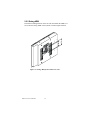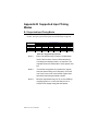
1
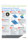
FPM-3175 Series
Industrial Flat Panel
Monitor with 17" LCD in
VGA/Video
Users Manual
Copyright
This document is copyrighted by Advantech Co., Ltd. All rights are
reserved. Advantech Co., Ltd. reserves the right to make
improvements to the products described in this manual at any time. Specifications are thus subject to change without notice.
No part of this manual may be reproduced, copied, translated, or transmitted in any form or by any means without the prior written permission of
Advantech Co., Ltd. Information provided in this manual is intended to
be accurate and reliable. However, Advantech Co., Ltd., assumes no
responsibility for its use, nor for any infringements upon the rights of
third parties which may result from its use.
All brand and product names mentioned herein are trademarks or registered trademarks of their respective holders.
FPM-3175 Users Manual
ii
FCC Class B
This equipment has been tested and found to comply with the limits for a
Class B digital device, pursuant to Part 15 of the FCC Rules. These limits
are designed to provide reasonable protection against harmful interference when the equipment is operated in a residential environment. This
equipment generates, uses and can radiate radio frequency energy. If not
installed and used in accordance with this user's manual, it may cause
harmful interference to radio communications. Note that even when this
equipment is installed and used in accordance with this user’s manual,
there is still no guarantee that interference will not occur. If this equipment is believed to be causing harmful interference to radio or television
reception, this can be determined by turning the equipment on and off. If
the interference is occurring, the user is encouraged to try to correct the
interference by one or more of the following measures:
•Reorient or relocate the receiving antenna
•Increase the separation between the equipment and the receiver
•Connect the equipment to a power outlet on a circuit different from that
to which the receiver is connected
•Consult the dealer or an experienced radio/TV technician for help
Part No. 2002317500
Printed in Taiwan
1st Edition
December 2001
Packing List
Before installing your equipment, make sure that the following materials
have been received:
•FPM-3175 Series flat panel monitor
•Accessory pack, including:
- AC/DC adapter
- Power Chord
- Video signal cable
- Component bag
- Screw bag
- HMI Products, Drivers, Utilities CD
- FPM-3175 Series User's Manual
- RS-232 cable (FPM-3175TVR-T only)
- TSCB-9516 drivers installation guide (FPM-3175TVR-T only)
If any of these items are missing or damaged, contact your
distributor or sales representative immediately.
Additional Information and Assistance
1.Visit the Advantech web site at www.advantech.com where you can
find the latest information about the product.
2.Contact your distributor, sales representative, or Advantech's customer
service center for technical support if you need
additional assistance. Please have the following information ready before
you call:
•Product name and serial number
•Description of your peripheral attachments
•Description of your software (operating system, version, application
software, etc.)
•A complete description of the problem
•The exact wording of any error messages
FPM-3175 Users Manual
iv
Safety Instructions
1. Read these safety instructions carefully.
2. Keep this User's Manual for later reference.
3. Disconnect this equipment from any AC outlet before cleaning. Use a damp
cloth. Do not use liquid or spray detergents for cleaning.
4. For plug-in equipment, the power outlet socket must be located near the equipment and must be easily accessible.
5. Keep this equipment away from humidity.
6. Put this equipment on a reliable surface during installation. Dropping it or letting it fall may cause damage.
7. The openings on the enclosure are for air convection. Protect the equipment
from overheating. DO NOT COVER THE OPENINGS.
8. Make sure the voltage of the power source is correct before connecting the
equipment to the power outlet.
9. Position the power cord so that people cannot step on it. Do not place anything
over the power cord.
10. All cautions and warnings on the equipment should be noted.
11. If the equipment is not used for a long time, disconnect it from the power
source to avoid damage by transient overvoltage.
12. Never pour any liquid into an opening. This may cause fire or electrical shock.
13. Never open the equipment. For safety reasons, the equipment should be
opened only by qualified service personnel.
14. If one of the following situations arises, get the equipment checked by service
personnel:
a. The power cord or plug is damaged.
b. Liquid has penetrated into the equipment.
c. The equipment has been exposed to moisture.
d. The equipment does not work well, or you cannot get it to work according to
the user's manual.
e. The equipment has been dropped and damaged.
f. The equipment has obvious signs of breakage.
15. DO NOT LEAVE THIS EQUIPMENT IN AN UNCONTROLLED
ENVIRONMENT WHERE THE STORAGE TEMPERATURE IS BELOW
-20° C (-4° F) OR ABOVE 60° C (140° F). THIS MAY DAMAGE THE
EQUIPMENT.
The sound pressure level at the operator's position according to IEC 704-1:1982 is
no more than 70dB(A).
DISCLAIMER: This set of instructions is given according to IEC 704-1. Advantech disclaims all responsibility for the accuracy of any statements contained
herein.
Wichtige Sicherheishinweise
1. Bitte lesen sie Sich diese Hinweise sorgfältig durch.
2. Heben Sie diese Anleitung für den späteren Gebrauch auf.
3. Vor jedem Reinigen ist das Gerät vom Stromnetz zu trennen. Verwenden Sie
Keine Flüssig-oder Aerosolreiniger. Am besten dient ein angefeuchtetes Tuch zur
Reinigung.
4. Die NetzanschluBsteckdose soll nahe dem Gerät angebracht und leicht
zugänglich sein.
5. Das Gerät ist vor Feuchtigkeit zu schützen.
6. Bei der Aufstellung des Gerätes ist auf sicheren Stand zu achten. Ein Kippen
oder Fallen könnte Verletzungen hervorrufen.
7. Die Belüftungsöffnungen dienen zur Luftzirkulation die das Gerät vor überhitzung schützt. Sorgen Sie dafür, daB diese Öffnungen nicht abgedeckt werden.
8. Beachten Sie beim. AnschluB an das Stromnetz die AnschluBwerte.
9. Verlegen Sie die NetzanschluBleitung so, daB niemand darüber fallen kann. Es
sollte auch nichts auf der Leitung abgestellt werden.
10. Alle Hinweise und Warnungen die sich am Geräten befinden sind zu
beachten.
11. Wird das Gerät über einen längeren Zeitraum nicht benutzt, sollten Sie es vom
Stromnetz trennen. Somit wird im Falle einer Überspannung eine Beschädigung
vermieden.
12. Durch die Lüftungsöffnungen dürfen niemals Gegenstände oder Flüssigkeiten
in das Gerät gelangen. Dies könnte einen Brand bzw. elektrischen Schlag auslösen.
13. Öffnen Sie niemals das Gerät. Das Gerät darf aus Gründen der elektrischen
Sicherheit nur von authorisiertem Servicepersonal geöffnet werden.
14. Wenn folgende Situationen auftreten ist das Gerät vom Stromnetz zu trennen
und von einer qualifizierten Servicestelle zu überprüfen:
a - Netzkabel oder Netzstecker sind beschädigt.
b - Flüssigkeit ist in das Gerät eingedrungen.
c - Das Gerät war Feuchtigkeit ausgesetzt.
d - Wenn das Gerät nicht der Bedienungsanleitung entsprechend funktioniert oder
Sie mit Hilfe dieser Anleitung keine Verbesserung erzielen.
e - Das Gerät ist gefallen und/oder das Gehäuse ist beschädigt.
f - Wenn das Gerät deutliche Anzeichen eines Defektes aufweist.
Der arbeitsplatzbezogene Schalldruckpegel nach DIN 45 635 Teil 1000 beträgt
70dB(A) oder weiger.
DISCLAIMER: This set of instructions is given according to IEC704-1. Advantech disclaims all responsibility for the accuracy of any statements contained
herein.
FPM-3175 Users Manual
vi
Table of Contents
Contents
Packing List ......................................................................................... iv
Additional Information and Assistance ............................................... iv
Safety Instructions ................................................................................ v
Wichtige Sicherheishinweise............................................................... vi
Chapter 1 Introduction ............................................................2
1.1
1.2
1.3
1.4
1.5
Introduction ................................................................................... 2
Specifications ................................................................................ 2
LCD Specification ......................................................................... 3
Connectors ..................................................................................... 4
Dimensions .................................................................................... 5
Figure 1.1: FPM-3175 Dimensions ................................................... 5
Chapter 2 System Setup ...........................................................8
2.1 Mounting the Monitor .................................................................... 8
2.1.1 Wall Mounting................................................................................. 8
Figure 2-1: Wall Mounting ............................................................... 8
2.1.2 Panel Mounting................................................................................ 9
Figure 2-2: Panel Mounting .............................................................. 9
2.1.3 Rack Mounting .............................................................................. 10
Figure 2-3: Rack Mounting ............................................................. 10
2.2 Desktop, Swingarm mounting ..................................................... 11
2.2.1 Desktop Stand ................................................................................ 11
Figure 2.4: Desktop Stand for the FPM-3175 series....................... 11
2.2.2 Swing-ARM................................................................................... 12
Figure 2.5: Swing-ARM for the FPM-3175 series.......................... 12
Appendix A Touchscreen Driver Installation ......................14
A.1 Introduction ................................................................................ 14
A.2 Touchscreen specifications......................................................... 14
A.3 Installation of Touchscreen Driver ............................................. 15
Appendix B Supported Input Timing Modes.......................18
B.1 Supported Input Timing Modes .................................................. 18
Table B-1: Supported Input formats ............................................... 18
Appendix C OSD Operation ..................................................20
C.1 OSD Operation Keypad .............................................................. 20
Table C-1: Keypad functions .......................................................... 20
C.2 OSD Function ............................................................................. 21
Figure C-1: OSD Menu ................................................................... 21
C.3 Feature Descriptions ................................................................... 21
C H APT E R
1
Introduction
This chapter includes:
•Introduction
•Specifications
•LCD Specification
•Connectors
•Dimensions
1
Chapter 1 Introduction
Chapter 1 Introduction
1.1 Introduction
Advantech's FPM-3175 Series is a 17" color TFT LCD flat panel monitor
built specifically for industrial applications. With the optional touchscreen, the FPM-3175 Series is an excellent and user-friendly system
control interface.
In addition to its usual application as an LCD panel monitor, the FPM3175 comes standard with Direct-VGA and Video interface, which not
only could directly connect to popular PC VGA cards, but also could connect to devices with video output, like cameras. With the FPM-3175,
Advantech is taking a more aggressive initiative to penetrate the industrial HMI market. Its OSD (On Screen Display) function allows you to
adjust the display factors and turn the backlight on and off for the front
view, functions which become critical as more and more industrial HMI
users become aware of the benefits of flat panel monitors. The whole
chassis is of stainless steel, and the front panel is of aluminum with
NEMA4/IP65 compliance.
The FPM-3175 provides a touch screen version (FPM-3175TVR-T) for
option. With an 8-wire resistive type touchscreen, the monitor can be
immediately transformed into a remote control system.
1.2 Specifications
General
• Control: OSD (On Screen Display) control pad on front side
• Mounting: Rackmount, panelmount, wallmount and VESA arm
mounting
• I/O port: VGA connector, Video connector, DC power input, power
switch, and RS-232 port (Touchscreen version only)
• Power Adaptor: External Power Adapter AC 110 V, +12 V @ 5 A
output
• Operating temperature: 0 ° ~ 50 ° C
• Storage temp: -20 ° ~ 60 ° C
• Storage humidity: 5% ~ 95% non-condensing
• Vibration (operating): 5 ~ 17 Hz, double-amplitude displacement
17 ~ 500 Hz, 1.0 G peak to peak
FPM-3175 Users Manual
2
• Dimensions: (W x H x D):482 x 354 x 68 mm (19" x 13.9" x 2.7")
• Weight:13.5 kg (29.8 lb)
• CE, FCC, BSMI, CCIB compliant
Touchscreen (Optional)
• Type: 8 wire, analog resistive
• Resolution: continuous
• Light transmission: 72%
• Operating Pressure: 30 ~ 45 gram for stylus pen, contact bounce <
10 ms
• Controller: RS-232 interface
• Power Consumption: +5 V @ 200 mA
• OS support: MS-DOS, Windows 3.1/95/98/NT/2000
• Life span: 100 million touches
1.3 LCD Specification
• Display type: SXGA TFT LCD
• Display size: 17"
• Max colors: full color (16 million)
• Max resolution: 1280 x 1024
• Dot pitch: 0.264 x 0.264 mm
• View Angle: 120° (H), 100° (V)
• Luminance: 250 cd/m2 4 CCFL
• Storage Temperature: -20° ~ 60° C
• Operating Temperature: 0° ~ 50° C
• Backlight Lifetime: 50,000 hrs
• Contrast Ratio: 300:1
3
Chapter 1 Introduction
1.4 Connectors
The following connectors are situated on the left hand side of the
FPM-3175 Series:
VGA Port (DB-15)
This DB-15 connector can be connected to the system via the external 15pin DB-15 connector located on the left side of the system unit.
Video Port (Mini-DIN 4 pin)
Support NTSC and PAL.
S-Video port
Touchscreen Connector (DB-9) (optional)
This connector will be present only if a touchscreen is installed. It must
be connected to the RS-232 port of the PC. The touchscreen cable is
included with all orders which include the touchscreen option.
DC 12 V Power in
This connector will be connected to the DC 12V Switching Power Supply.
Extended Cable Transmission (optional)
A 5/20/30/50-meter VGA cable is provided for special applications.
Another longer cable is also available. For more detailed information,
please contact our dealers.
FPM-3175 Users Manual
4
1.5 Dimensions
Cutout Dimensions: 451 x 340 mm (17.8" x 13.4")
Figure 1.1: FPM-3175 Dimensions
5
Chapter 1 Introduction
FPM-3175 Users Manual
6
C H APT E R
2
System Setup
This chapter includes:
•Mounting the Monitor
- Wall/Panel/Rack Mounting
- Desktop Stand/Swing-ARM Mounting
7
Chapter 2 System Setup
Chapter 2 System Setup
2.1 Mounting the Monitor
The FPM-3175 Series can be placed as you require. The versatility of
the FPM-3175 mounts enable it to be mounted on your desk or anywhere
else.
2.1.1 Wall Mounting
With wall brackets, the FPM-3175 can be mounted directly to a wall.
If you need to install the FPM-3175 in different ways, release the mounting brackets by detaching the four screws on the rear side.
Figure 2-1: Wall Mounting
FPM-3175 Users Manual
8
2.1.2 Panel Mounting
If you need to install the FPM-3175 series on a panel mount, please
release the mounting brackets by detaching four screws on rear side and
fix them on up and bottom side by screws.
Figure 2-2: Panel Mounting (cut out dimension: 451 mm x 340 mm)
9
Chapter 2 System Setup
2.1.3 Rack Mounting
FPM-3175TVR series products could be directly mount to the industrial
standard 19" rack. There are four screw holes on each side of the panel.
Figure 2-3: Rack Mounting
FPM-3175 Users Manual
10
2.2 Desktop, Swingarm mounting
The FPM-3175 Series can be mounted in other ways. You can place the
desktop stand for desktop use or attach it on a swing-arm bracket.
2.2.1 Desktop Stand
The desktop stand bracket is attached to the rear of the FPM-3175. Simply detach the small bracket at the top of the monitor by unscrewing the
two screws. The lower bracket now becomes the desktop stand bracket.
Figure 2.4: Desktop Stand for the FPM-3175 series
11
Chapter 2 System Setup
2.2.2 Swing-ARM
Detach the mounting brackets on the rear side, then attach the FPM-3175
series onto the Swing-ARM mount (75mm or 100mm square bracket).
Figure 2.5: Swing-ARM for the FPM-3175 series
FPM-3175 Users Manual
12
A p p e n d ix
A
Touchscreen Driver
Installation
•Introduction
•Specification
•Installation
13
Appendix A Driver Installation
Appendix A Touchscreen Driver
Installation
A.1 Introduction
The FPM-3175 Series’ optional touchscreen uses an advanced 8-wire
resistive technology. It provides more accurate sensing capacity than
other technologies. The touchscreen is specially designed for tough
industrial environments, and has been approved to FCC Class A and
Class B standards.
A.2 Touchscreen specifications
Electrical
• Contact bounce: < 10 ms
• Operating voltage: 5 V (typical)
• Contact current: 20 mA (max.)
• Circuit resistance: Open: > 30 mohms
Closed: < 2000 mohms
• Sheet resistance variation: Within one screen: ± 5%
From screen to screen: ± 20%
Durability
Test conditions: 4H hardness, 0.04" stylus pen, 350 gram load
• Point activation:
Single point, position of stylus controlled to ± 0.0005"
Result: > 1 million activations
• Linear activation:
2" diagonal line, position of stylus controlled to ± 0.0005"
Result: > 250,000 cycles
• Chemical resistance: Hard coating is highly resistant to most
solvents and chemicals
Optical
• Visible light transmission: 72% (typical)
• Reflection: > 25% @ 550 nm
FPM-3175 Users Manual
14
Sensor board
• Chemical strengthened glass meets “4H” hardness standard (Test
condition: ASTM D3363-92A
Ball drop test
• Touchscreen can withstand a 225 g steel ball dropped from a height of
660 mm, without breaking
Environmental
• Operating pressure: 30 ~ 45 grams for finger; 10 grams for stylus
pen
• Operating temperature: 0 ~ 50° C (humidity 20 ~ 90% RH)
• Storage temperature: -25 ~ 70° C (humidity 20 ~ 95% RH)
A.3 Installation of Touchscreen Driver
The touchscreen into the FPM-3175 Series provides drivers for use with
MS-DOS, Windows 3.1, 95, 98, NT and 2000. For the detail touchscreen
drivers installation procedure, please refer "TSCB-9516 drivers installation guide" in the accessory box.
15
Appendix A Driver Installation
FPM-3175 Users Manual
16
A p p e n d ix
B
Supported Input Timing
Modes
17
Appendix B Supported Input Timing
Modes
B.1 Supported Input Timing Modes
The nineteen kinds of timings below are already programmed in this
module. The input synchronous signals are automatically recognized.
Resolution
640x480
800x600
1024x768
1280x1024
1600x1200
56Hz
Yes
60Hz
Yes
Yes
Yes
Yes
Yes
Vertical Frequencies
70Hz
72Hz
Yes
Yes
Yes
Yes
Yes
75Hz
Yes
Yes
Yes
Yes
85Hz
Yes
Yes
Yes
Yes
Table B-1: Supported Input formats
Note 1:
Even if the preset timing is entered, a little adjustment of the functions such as Horizontal period,
CLK-delay and display position, are required. The
adjusted values are memorized in every preset number.
Note 2:
This module recognizes the synchronous signals
with near preset timing of the frequency of the HS
and Vsync, even in the case that the signals other
than the preset timing that were entered.
Note 3:
Because adjustments may not fit, such as differing
magnifying ratios or, in the case that you use it
except for the display timing that was preset.
FPM-3175 Users Manual
18
A p p e n d ix
C
OSD Operation Keypad
19
Appendix C OSD Operation
C.1 OSD Operation Keypad
The OSD keypad, including six keys and a two color indicator, is
designed as the OSD operation interface.
The six keypad functions are in Table C-1.
Auto
Press this button to execute auto adjustment process
Sel
Press to show the OSD screen or select an item to
change its setting
!"#
To move between items or increase or decrease setting
Exit
This key has two functions:
1.) To exit from the current setting in OSD function
2.) To switch the input source between RGB, Video and
S-Video
On/OFF
Turns display backlight ON and OFF
Table C-1: Keypad functions
Note: The green light means that the COMMON board detects the input signal and ends output signal to LCD panel.
FPM-3175 Users Manual
20
C-2 OSD Function
Each selected value is stored into LCD memory after SEL signal input or
time out. The stored values are not affected if the power is turned off. But
the selected value is not available in case a selected mode is changed
before time out or power is turned off before time out.
Figure C-1: OSD Menu
C.3 Feature Descriptions
Brightness- Press the WandXkeys to adjust the brightness. Note: this
menu adjusts the back-light intensity using the PWM feature.
Contrast- Press the WandX keys to adjust the contrast. Note: this menu
adjusts the contrast using the digital contrast control.
Language- Press the X key to select the language of your choice.
Advanced Features- Press the X key to access advanced features of this
monitor.
Exit- Press theXkey to exit the menus.
21
Appendix C OSD Operation
Digital Color Controls- Press the "# key to adjust the digital controls such
as black level, red/green/blue gain, hue & saturation, flesh-tone compensation
and color.
Analog Settings- Press the "# key to adjust controls such as brightness,
contrast, Horizontal and vertical position, phase, clocks per line and auto configuration.
OSD Settings- Press the "# key to adjust OSD controls such as time out, H
and V- position and OSD size.
Misc- Press the "# key to adjust miscellaneous settings such as sharpness
control, moire cancellation, scaling enhancement, factory reset, force input
and overlap modes.
Digital Brightness- Press the !"and"# keys to digitally adjust the brightness.
Black Level- Press the !"and"# keys to adjust digital black level control.
Red Level- Press the !"and"# keys to adjust the digital red level.
Green Level- Press the !"and"# keys to adjust the digital green level.
Hue- Press the !"and"# keys to digitally adjust the hue.
Saturation- Press the !"and"# keys to adjust saturation.
Real Color™ Flesh Tone Adjustment- Press the !"and"# keys to digitally compensate for flesh tones.
Color Temperature- Press the !"and"# keys to select a color temperature
that makes screen white look like paper white.
H-Position- Press the !"and"# keys to move the screen left or right along
the capture window.
V-Position- Press the !"and"# keys to move the screen up or down by
moving the analog capture window.
Phase- Press the !"and"# keys to adjust the sampling phase of the analog
to digital converter.
FPM-3175 Users Manual
22
Clocks- Press the !"and"# keys to adjust the number of clocks per line in
the analog to digital converter.
Auto Config- Press the # key to automatically configure the above settings.
OSD-Timeout- Press the !"and"# keys to decrease or increase the
amount of time that elapses before the menu disappears.
OSDH-Position- Press the !"and"# keys to adjust the horizontal position
of the menu.
OSDV-Position- Press the !"and"# keys to adjust the Vertical position of
the menu.
OSDSize- Press the !"and"# keys to decrease or increase the size of the
menu.
Low Zoom Factor Sharpening- Press the !"and"# keys to use adaptive
Contrast Enhancement to adjust the sharpness when scaling textual images.
High Zoom Factor Sharpening- Press the"# key to select a different video
filter that sharpens graphical images when scaling from very low resolutions
or press Press the !"key to select a smoother scaling algorithm.
Moire Cancellation- Press the !"and"# keys to remove patterns due to
non-linearities when scaling from a low resolution to SXGA resolution (or
XGA resolution, depending on panel).
Select Source- Press the !"and"# keys to select the input source you
would like to view. Use ‘AUTO’ to let the monitor do it automatically.
(AUTO selects in the following priority: Digital RGB, Analog RGB, S-Video,
Composite Video initially. When there is more than one input active, the
source remains the previously active source).
Factory Reset- Press the # key to reset all user settings and then confirm user
settings. The stored in NVRAM will be lost.
Analog Brightness- Press the !"and"# keys to adjust analog RGB offset.
Analog Contrast- Press the !"and"# keys to adjust analog RGB gain.
23
Appendix C OSD Operation
Red Gain- Press the !"and"# keys to adjust the red gain.
Green Gain- Press the !"and"# keys to adjust the green gain.
Blue Gain- Press the !"and"# keys to adjust the blue gain.
Firmware version- This monitor uses software version X.XX
Overlapped Modes- Press the !"and"# keys to tell the monitor to use DOS
mode timings (720 pxl/line) or EGA/CGA timing (640 pxl/line) when these
modes are otherwise indistinguishable.
Switcher OFF/ON- Press the# key to deactivate format detection or press the
!"key to activate format detection.
FPM-3175 Users Manual
24