Transcript
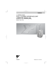
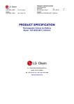
APPLICABLE SERVOPACKs IN THE
Series Indexer Module
SERIES
x Command Option Attachable Type
Installing the Board
SAFETY PRECAUTIONS
3.Hold both ends of
Before starting
Installation Guide
CAUTION
y Always wear an antistatic wrist strap that is safely grounded.
ITEMS REQUIRED FOR INSTALLATION
y Touch a safely grounded object to discharge any static electricity
from your body.
Package Contents
Mounting the Module Cover
A
7.Align the front end
the board (A) as
shown in the
illustration, and
firmly insert the
board connector
into the connector
port on the
SERVOPACK.
Installation
A-Board
CAUTION
Insert the board connector firmly
into the connector port.
y Install in the specified environment.
Pre-attached screws
Failure to observe this caution may result in malfunction.
y Disconnect all cables from the SERVOPACK before installing the board.
Failure to observe this caution may result in malfunction.
4.Fix the board on the
B-Mounting
Screws
SERVOPACK with five
screws.
y Do not apply any impact to the board.
Failure to observe this caution may result in malfunction.
B
( Tightening torque: 0.14 Nxm )
board is an example and may
* : This
differ from the received product.
y Do not touch the connector or electronic components on the board.
Hold the board along its edges when installing.
Failure to observe this caution may result in malfunction.
y Do not place any object on the board.
Failure to observe this caution may result in malfunction.
Failure to observe this caution may result in malfunction.
I
H-Module cover
I -SERVOPACK
Retention clip
angled end protrusion
Push the clips in the
direction indicated by the
arrow so the clip will go
into the SERVOPACK.
Retention clip
Tighten these
pre-attached screws
as well.
y Avoid direct contact with any object that has not had antistatic treatment.
Bottom
Front panel
the SERVOPACK by
pushing in the retention
clips on the left and
right side of the
module cover, while
directing their angled
end protrusions to
enter the SERVOPACK.
B
Failure to observe this caution may result in malfunction.
B-Mounting screws for
board (3)
H
8. Fix the module cover to
y Protect the board from moisture.
A-Board*
of the module cover
(H) with the front
panel of the SERVOPACK as shown
in the illustration,
and place the
module cover so
that you can view
the installed board
from the opening
(where the front
cover is removed) on
the module cover.
Retention
clip
y Make sure that your clothing is not in contact with the board.
Failure to observe this caution may result in malfunction.
y Do not tighten the screws with excessive torque.
MANUAL NO. TOBP C720829 02A
This installation guide explains how to mount the
Series Indexer
module onto the
Series SERVOPACK. Read this installation guide
thoroughly as well as the safety precautions ( TOBP C720829 00 )
included with the product.
C-Nameplate (Ratings)
D-Nameplate (Model no.)
Additional Items (not included)
without covers or protective guards. Always replace the equipment’ s
cover or protective guard as specified first, and then operate the
products in accordance with the user’ s manual.
Preparing the Module Cover
INSTALLATION PROCEDURE
Option Case Kit*
(Model: SGDV-OZA01A)
1.Fit the mounting plate (F)
( Tightening torque: 0.14 Nxm )
y The drawings presented in this instructions are typical examples and
F
G
x Do not remove the other front cover.
Front covers
I
may not match the product you received.
y These instructions are subject to change due to product improvement,
specification modification, and instructions improvement. When these
instructions are revised, the instructions code is updated and the new
instructions is published as a next edition.
y If the instructions must be ordered due to loss or damage, inform
H-Module cover
K-Screwdriver
I-SERVOPACK
F-Mounting plate
ordering, refer to the
* : When
catalog (KAEP S800000 42).
Series
J-Phillips screwdriver
K-Screwdriver
Back F -Mounting plate
G-Mounting screws
I -SERVOPACK
y The following conventions are used to indicate precautions in these
instructions.
y Failure to heed these precautions can result in serious or possibly even fatal
injury or damage to the products or to related equipment and systems.
Indicates precautions that, if not heeded, could
WARNING possibly result in loss of life or serious injury.
Indicates precautions that, if not heeded, could
CAUTION result in relatively serious or minor injury, damage
Always leave the option module attached to the SERVOPACK
when sending the option module to YASKAWA for service.
Series Indexer Module
Installation Guide
IRUMA BUSINESS CENTER (SOLUTION CENTER)
480, Kamifujisawa, Iruma, Saitama 358-8555, Japan
Phone 81-4-2962-5696 Fax 81-4-2962-6138
YASKAWA ELECTRIC AMERICA, INC.
6.Affix two nameplates (C, D) to
2121 Norman Drive South, Waukegan, IL 60085, U.S.A.
Phone (800) YASKAWA (800-927-5292) or 1-847-887-7000 Fax 1-847-887-7370
the positions specified in
illustration.
YASKAWA ELETRICO DO BRASIL LTDA.
Avenida Fagundes Filho, 620 Sao Paulo-SP CEP 04304-000, Brazil
Phone 55-11-3585-1100 Fax 55-11-5581-8795
YASKAWA ELECTRIC EUROPE GmbH
Hauptstraβe 185, 65760 Eschborn, Germany
Phone 49-6196-569-300 Fax 49-6196-569-398
INSTALLATION CONDITIONS
2.Remove the connector cover
Install the module in the following environment.
If You Need to Send Us the Option Module for Service
H
Top
y Yaskawa will not take responsibility for the results of unauthorized
Safety Information
Insert a
screwdriver here
to remove the
front covers.
H-Module cover
your nearest Yaskawa representative or one of the offices listed on
the back of this instructions.
modifications of this product. Yaskawa shall not be liable for any
damages or troubles resulting from unauthorized modification.
Conduct a trial operation after the Indexer module has been
properly installed on the SERVOPACK.
For trial operation details, refer to
Series User’ s Manual:
Setup Rotational motor/Linear motor (SIEP S800000 43/44).
K
(shown in the illustration) from
the module cover (H) with a
screwdriver (K ).
G
into the recess on the
SERVOPACK, and fix the
plate with the mounting
screws (G).
G-Mounting
screws for
plate (2)
After Installing
5.Remove the front covers
Preparing the SERVOPACK
General Precautions
y The drawings presented in this instructions are sometimes shown
The recommended tightening torque is 0.14 Nxm ±10%.
Tightening screws with excessive torque may damage screw threads
and the spacer, resulting in deformation of the board.
from the SERVOPACK.
YASKAWA ELECTRIC UK LTD.
Connector cover
D
1 Hunt Hill Orchardton Woods Cumbernauld, G68 9LF, United Kingdom
Phone 44-1236-735000 Fax 44-1236-458182
YASKAWA ELECTRIC KOREA CORPORATION
7F, Doore Bldg. 24, Yeoido-dong, Youngdungpo-Ku, Seoul 150-877, Korea
Phone 82-2-784-7844 Fax 82-2-784-8495
y Cover the working area with a conductive or antistatic mat.
YASKAWA ELECTRIC (SINGAPORE) PTE. LTD.
y This mat must be safely grounded with a resistor (1 MΩ ± 20%).
C
151 Lorong Chuan, #04-01, New Tech Park 556741, Singapore
Phone 65-6282-3003 Fax 65-6289-3003
YASKAWA ELECTRIC (SHANGHAI) CO., LTD.
No.18 Xizang Zhong Road. Room 1702-1707, Harbour Ring Plaza Shanghai 200001, China
Phone 86-21-5385-2200 Fax 86-21-5385-3299
y The surrounding air temperature must be between 0 and 55˚C.
YASKAWA ELECTRIC (SHANGHAI) CO., LTD. BEIJING OFFICE
y Ambient humidity must be 90˚C RH or less (with no condensation).
Room 1011A, Tower W3 Oriental Plaza, No.1 East Chang An Ave.,
Dong Cheng District, Beijing 100738, China
Phone 86-10-8518-4086 Fax 86-10-8518-4082
y No extreme changes in temperature that can cause condensation
YASKAWA ELECTRIC TAIWAN CORPORATION
9F, 16, Nanking E. Rd., Sec. 3, Taipei, Taiwan
Phone 886-2-2502-5003 Fax 886-2-2505-1280
y Free from corrosive or flammable gases
y Free from dust, salts, or iron dust
to the product, or faulty operation.
y Not subject to water, oil, or chemicals
In some situations, the precautions indicated could
have serious consequences if not heeded.
y No vibration and/or shock directly transmitted to the product
C-Nameplate(Ratings)
D-Nameplate(Model no.)
The product is under
warranty only when the
nameplate (C) is attached.
YASKAWA ELECTRIC CORPORATION
YASKAWA
In the event that the end user of this product is to be the military and said product is to be employed in any weapons
systems or the manufacture thereof, the export will fall under the relevant regulations as stipulated in the Foreign
Exchange and Foreign Trade Regulations. Therefore, be sure to follow all procedures and submit all relevant
documentation according to any and all rules, regulations and laws that may apply.
Specifications are subject to change without notice
for ongoing product modifications and improvements.
© 2009 YASKAWA ELECTRIC CORPORATION. All rights reserved.
MANUAL NO. TOBP C720829 02A
Published in Japan April 2009 09-4
09-1