1
VL Series Manual
INDEX
1
TECHNICAL FEATURES
2
TECHNICAL SPECIFICATION
2.1
OVERALL DIMENSIONS AND WEIGHTS
PERFORMANCE
2.2
CONVEYED FLUID
2.3
VISCOSITY OF THE POURED OUT LIQUIDS AND SUCTION PRESSURE
2.3.1
3
SAFETY AND PREVENTION OF ACCIDENTS
4
INSTALLATION
PRECAUTION AT ASSEMBLY
4.1
POWER DRIVE
4.2
CARDAN DRIVE
4.2.1
4.2.2 TRANSMISSION WITH BELTS
DIRECT TRANSMISSION
4.2.3
4.2.4 HYDRAULIC TRANSMISSION/DRIVE
4.3
INSTALLATION D’ASPIRATION ET SYSTEMES DE PROTECTION
5
STARTING THE SYSTEM
PRECAUTION DURING USE
5.1
6
MAINTENANCE
6.1
OPRDINARY MAINTENANCE
6.2
EXTRAORDINARY MAINTENANCE
Disassembling of the pump
6.2.1
6.2.1.1
6.2.1.2
6.2.1.3
6.2.1.4
6.2.1.5
6.2.2
Disassembly sequence VL 7 - VL14 - VL20 (Refer to VL 14 spare parts sheet)
VL 27 disassembly sequence
Lobes disassembly of model VL 7 – VL14 – VL 20
Lobes disassembly of model VL 27
Disassemble of seals and bearing housing
REASSEMBLE
6.2.2.1
6.2.2.2
6.2.2.3
6.2.2.4
6.2.2.5
6.2.2.6
6.2.2.7
6.2.2.8
6.2.2.9
End plate- housing and wearplate group
Axle– lobe group
Seal/bearing group
Assemble of the pump housing – lobes – end plate VL
Timing and blocking of gears for VL 7 – VL14 – VL 20 – VL 27
Assemble of the front chamber and of the lobe – housing group VL 27
Assemble of the front end plate – housing of VL 7 – VL14 – VL 20 – VL 27
Assemble of the oil tank and lubrification of the gears
Checking of the running
7
MARKING
8
TROUBLE SHOOTING
9
SCRAPPING
10
REQUEST FOR SPARE PARTS
1
TECHNICAL FEATURES
This booklet contains the necessary instructions for a correct installation, running test, normal
use and maintenance of the pump as well as practical suggestions for safe operating in
conformity with the legislation in force.
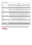
The most important points are indicated with the following symbols:
DANGER: The texts preceded by this symbol provide safety norms whose nonobservance may gravely harm persons.
WATCH OUT!: The texts preceded by this symbol provide safety norms, failure to
comply with which may damage either the pump or the transmission.
ENVIRONMENT PROTECTION: The texts preceded by this symbol provide
suggestions for an environmentally-friendly use and maintenance of the pump.
USEFUL SUGGESTIONS: The texts preceded by this symbol provide useful advice to
make the machine’s use easier.
ATEX directive
The ATEX EC/94/9 directive defines the essential requirements for protection apparatuses and
systems destined for being used in a potentially explosive atmosphere such as gas, steams,
fogs and inflammable dusts. The VL series pumps marked with the Ex symbol are classed for
employment in potentially explosive atmospheres defined group II, category 2 and 3 by the
ATEX EC/94/9 directive.
ATEX CONFORMITY: The texts preceded by this symbol provide compulsory rules
regarding installation, employment and maintenance of the ATEX-certified pumps.
Observe the data provided on the little embossed metal plate. Observe
peremptorily the directions this maintenance manual provides.
Non-observance forfeits all the requirements fixed by the directive, and releases the
manufacturer from all liability resulting from the employment of the machine in a
potentially explosive atmosphere.
All operations, such as transport, storage, assembly, start-up, maintenance and repairing,
must be performed outside all explosive atmospheres.
All operations, such as transport, storage, assembly, start-up, maintenance, repairing and use,
must be exclusively carried out by qualified and specialised staff that are aware of this
user’s manual’s contents.
2
TECHNICAL SPECIFICATION
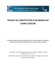
2.1
OVERALL DIMENSIONS AND WEIGHTS
Fig.1
ROTARY LOBE PUMPS - VL SERIES Ex (Tab.1)
Dimensions mm
Model
A
B
C
D
E
VL 7
135
140
135
158
14
VL 14
135
140
135
223
14
VL 20
135
140
135
289
14
VL 27
135
140
135
366
14
VL 40
135
140
135
497
14
F
ASA E 1 3/8"
DIN 9611A
ASA E 1 3/8"
DIN 9611A
ASA E 1 3/8"
DIN 9611A
ASA E 1 3/8"
DIN 9611A
ASA E 1 3/8"
DIN 9611A
G
H
I
L
M
N
P
580
410
230
DN 80
274
463
35g6
Kg
97
510
470
230
DN 100
274
463
35g6
105
610
534
230
DN 150
274
463
35g6
119
610
613
230
DN 150
274
463
-
146
828
747
230
DN 175
274
463
-
170
All running under regimes and /or pressure levels higher than those indicated in the table is
forbidden.
2.2
PERFORMANCE
Model
VL 7
VL 14
VL 20
VL 27
VL 40
Fig.2
velocity
[rpm]
540
540
540
540
540
maximum
flow
[l/min]
700
1400
2000
2700
4000
maximum
pressure
[bar]
5
5
5
5
3
Power
[kW]
8
17
25
34
42
SUGGESTED LUBRICANTS (Tab. 2)
Pump lubrification
Brand
AGIP
BP
ESSO
MOBIL
SHELL
Fig.3
Oil
(ISO 320)
Blasia 320
Energol GR-XP 320
Spartan EP 320
Mobilgear 632
Omala oil 320
Grease
(ISO 280)
GR MU EP2
Grease LTX2
Beacon 2-Esso GR grease
Mobilplex 47
Alvania grease R2
The self-priming, VL pumps, in the start-up stage can ‘dry’ run but only for short periods.
To avoid superficial temperatures outreaching the fixed class, the 10 second-maximum value
must never be exceeded. Please refer to the level device application in section 4.3.
2.3
CONVEYED FLUID
VL Ex pumps are conceived for conveying viscous, fibrous products, muds and pastes at a
maximum 40 °C temperature.
Fluids containing abrasive solid materials in suspension up to a 10 mm diameter may be
conveyed provided they have no cutting edges/profiles and cause no anomalous vibrations in
the machine.
Peremptorily avoid the entrance of remarkably big solid bodies into the pumps. Such a
possibility, in fact, may cause a sudden blocking of the pump with ensuing likely
breakage of the transmission gears.
That is why a suction filter must be applied to withhold particles larger than 10 mm
MAX and having a passage section able to guarantee a delivery that is at least twice
that of the pump. Clean the filter periodically to avoid cavitation ( see sect.6.1 ).
In the case of cardan transmission/drive we suggest to assemble the cardan shaft with
a safety pin.
Verify the chemical compatibility of the matter to be conveyed with the lobes’ inner lining,
according to what is indicated in the following table:
Tab.3
Lobes
NBR
EPDM
VITON
POLYURETHAN
Generally resistant to
most hydrocarbons,fats, oils,
hydraulic fluids, chemicals.
vegetable and animals fats, oils,
ozone, strong and oxidizing
chemicals.
aromatic, aliphatic, alogenated
hydrocarbons, acids, animal/vegetable
oils.
mineral oils, solvents, aromatic
hydrocarbons.
ketones, low mole weight esters, nitro
containing compounds.
poor
poor
excellent
poor
excellent
excellent
poor
excellent
mineral oil, aromatic and
aliphatic hydrocarbons, many
nitrils.
acids, phenols, toluene,
aldeydes and ketones,
chlorinated hydrocarbons.
very good
very good
poor
very good
ozone, ketones, esters,
aldeydes,nitro and chlorinated
hydrocarbons.
very good
good
fair
good
Generally attacked to
Resistance
oil
fuels
ketones
hydrocarbons
If the matter to be conveyed is not indicated in the table, please contact our customer service
office.
If you expect not to employ the pump with Viton lobes for a long time, wet the lobes
with a lot of water and in safety conditions before stopping it. In the opposite case the
priming of electrostatic discharges between the lobes and the housing is likely at startup.
2.3.1
VISCOSITY OF THE POURED OUT LIQUIDS AND SUCTION PRESSURE
Fig.4
8
7
NPSHr [m]
6
5
4
3
2
1
0
350
375
400
425
450
475
500
525
550
Regime [rpm]
VL7-VL14-VL20
VL27-VL40
575
600
The viscosity of a liquid, indicating the
resistance that it opposes to its being moved,
increases considerably when the temperature
decreases.
Because of viscosity, pressure falls shall occur
in the suction line and overpressure in the
discharge line.
To prevent anomalies in running, above all
when inflammable liquids are to be conveyed,
keep pressure at the suction flange sufficiently
high in order not to prime the cavitation
phenomenon.
Before starting to use the equipment, verify that the suction plant’s NPSHa is higher
than the pump’s NPSHr value, which can be deduced from the chart in illn. no. 4.
Determine static pressure’s minimum value at the suction flange, and verify that
during use you do not go under this limit. Also read section 4.3. In case you have
any doubt, please contact our customer-service office.
Should you be conveying highly viscous liquids, we suggest you decrease pressure losses
along the lines by reducing the rotation regime, employing the suggested diameters, and short
suction ducts as well. If possible, install the pump under head.
3
SAFETY AND PREVENTION OF ACCIDENTS
If the safety rules are not abided by, operators may suffer injuries due to contact with moving
gears. Should anomalous features be noticed while the machine is running (abnormal
absorption, increases in temperature, noisiness, vibrations), please inform the staff in charge of
maintenance.
CARRY OUT THE FOLLOWING PRECEPTS VERY CAREFULLY
• When transporting the pump use suitable slings.
• Installation and maintenance shall be performed only by qualified personnel with the
following pre-requisites:
• Experience and specific technical training;
• Knowledge of the technical norms and applicable laws;
• Knowledge of all safety directions: domestic, local, general and of the plant;
• Ability in recognising and avoiding likely danger;
• Use of the appropriate clothing, the necessary protections and instruments.
• Before any maintenance operation:
• Stop the pump and restore the system at the surrounding pressure condition (vent
the whole plant);
• Disengage the power transmission;
• Works only on cold and stopped pump.
• Operators working at short distances from the running pump should avoid to be exposed for long
periods of time to the noise of generated by the machine, unless wearing adequate protections.
• Non The machine must never be started without the safety devices foreseen for the drive
elements. Change any damaged guard.
• Do not use the pump above the given performance values that could result in breakdowns
and consequent damages of the drive components and to the operators.
Dispose of exhausted oils according to regulations in force.
4
INSTALLATION
CONTROL AT RECEPTION
• Remove the packaging and eliminate the material that may become dangerous if inhaled.
• At arrival of goods, verify that all components are not damaged.
• Make sure the pump has its identification plate. Pumps without such identification are
considered anonymous and potentially dangerous: in such a case they must not be used,
otherwise the manufacturer will be free from any liability whatsoever. In such an event,
contact the manufacturer or retailer.
CONSERVATION IN THE WAREHOUSE
If you foresee not to use the pump for a long time:
• introduce a layer of grease inside the housing and, by rotating the pistons manually, lubricate
the surfaces subject to oxidation.
• Keep in a closed and dry place. Do not remove the protections on the inlets. For
conservation purposes, repeat these operations periodically.
4.1
PRECAUTION AT ASSEMBLY
Pump’s location must be chosen to let an easy maintenance an check. The pump must be
rigidly fixed to a levelled-off frame or bed (max. inclination = 5°). The size of the structure must
be such as to avoid any bending or vibrations.
• Avoid exposition to dust, rubble/deposits or projection of materials.
• Predispose the room required to reach:
• The condensation draining plug on the lower side of the pump’s housing.
• The level of the oil tank
• The oil filling and draining plugs on the tank
• The lid of the rear oil tank
• The front seals groups
• Support the piping connecting the pump to avoid overexertion on inlets.
Carry out assembly operations outside any whatever potentially explosive
atmosphere.
Do not tilt the pump more than 5° with respect to the horizontal line.
Ensure the pump cannot accumulate static electricity by grounding it
electrically. To said end, use the holes at the foot of the machine.
Allow for free passage of air on all sides of the machine.
Neither embed nor cover the pump.
The bed must not convey heat into the machine while it is running.
4.2
POWER DRIVE
For running to take place in explosive ambiences, since all transmission components
are potential primers, they must comply with the ATEX directive and be marked at least
Ex II 2G, with temperature class T4,T5 or T6.
4.2.1
CARDAN DRIVE
We suggest using telescopic type cardan shafts. The cardan must be mounted in a
way to avoid axial forces. Upper inclinations angle 15° (fig.4). Rotation must be as
regular as possible (homo-kinetic transmission). Follow the directions provided by the
cardan shaft’s manufacturer.
Employ appropriate cardan protections: the pump’s installation must be carried out in
compliance with EC accident prevention legislation.
4.2.2
TRANSMISSION WITH BELTS
The pulley must be installed on the smooth pump shaft jutting-out as little as possible.
Use SPB or SPBX trapezoidal belts.
The smallest pulley employed for transmission must have the following features:
Tab.4
Model
Minimum n° of
grooves
Minimum pitch
diameter [mm]
3
6
6
-
160
160
180
-
VL 7
VL 14
VL 20
VL 27
VL 40
Use the least number of belts.
Use pulleys with a primitive diameter bigger than the minimum one prescribed.
Do not apply an excessive pull on the belts: follow the manufacturer’s directions (illn.
6).
Transmission must be protected according to norms in force in Europe (EEC directive no.
89/392 on machines).
Fig.5
4.2.3
Fig. 6
DIRECT TRANSMISSION
Should you install a flexible joint, control its alignment with a comparator in at least four points
equally far away on the periphery. Failure to ensure alignment may quickly wear out the joint
and the bearings.
4.2.4
HYDRAULIC TRANSMISSION/DRIVE
The directions given hereafter refer to the hydraulic transmission adopted by JUROP in noncertified versions.
• Motor features we suggest
Model
Displacement
cc/rev
rpm
Working
pressure
bar
34
43
61
72
72
2000
2000
2000
2000
2000
95
150
153
149
183
VL 7
VL 14
VL 20
VL 27
VL 40
Velocity
Maximum pressure at draining line: 5 bar
Delivery
72
91
129
152
152
l/min
Maximum pressure of motor discharge: 5 bar
Between the suggested motor and the pump there shall have to be an adequate reduction
gear with a velocity ratio equal to 1:3.7.
• Fluid: mineral oil for hydraulic plants according to ISO/DIN
Temperature
°C
Optimal viscosity
cSt
Max. consented viscosity
cSt
-20 / +80
12 - 100
750
• Filtering: contamination class 19/16 according to ISO 4406 to be
obtained with a ßx filter = 75
• Verify the circuit’s connections: they must be coherent with the
pump’s rotation direction with regard to the protections installed in
the plant.
Rotation in the wrong direction shall render the protections
ineffective.
• Draining: connect directly to the plant’s tank above the maximum oil level. Machine running
without draining may damage the motor.
Fig.7
Pos
Description
1
Hdr pump
2
Distributor
3
Hdr motor
4
Oil filter
5
Heat exchanger
6
Safety valve
• Distributor: with open ports in the rest position. The distributor must be fitted with an
adjustable over-pressure safety relief valve.
• Motor piping: with a nominal diameter at least equal to that of the motor ports The diameter
of the motor inlet pipe is always smaller than the discharge. Prefer flexible piping to avoid
conveying vibrations.
• Tank: with feeling and return pipes spaced and separated by partition. If necessary use a
heat exchanger to avoid overheating the oil (max 70°C) with a safety valve to avoid pressure
peaks should the circuit be obstructed. The capacity is about twice the quantity of oil
circulating (in l/min).
• Starting: make sure the system is perfectly clean and put oil in the tank, using a filter.
• Vent off the circuit. Adjust the pressure limiting valve to the lowest possible value.
• Check the level of the oil in the tank.
• Increase pressure and rotation until the working values are reached.
4.3
INSTALLATION D’ASPIRATION ET SYSTEMES DE PROTECTION
Realise the plant according to the information provided in illn. no. 8.
When overpressure is possible at discharge due to: clogging of the line ( unclean fluids with
suspended solids), non-voluntary closing of the valves or a change in the fluid’s thermodynamic state, protect the pump with an appropriate safety device.
The device may be a maximum pressure valve, in conformity with the requirements set out in
the ATEX directive as a control and protection system with Ex II 2G marking and T4,T5 or T6
temperature class. The valve shall have to re-circulate, at suction, a delivery that is sufficient to
keep working pressure within the maximum allowed limits (5 bar per VL 7, VL 14, VL 20 and VL
27e of 3 bar per VL 40). Calibrate the valve with precision before you set it to work.
Should the device intervene, the operator shall immediately have to:
• Stop the machine;
• Determine and solve the cause that provoked the overpressure;
• Clean the overpressure valve accurately without changing its calibration;
• Start up the plant again.
Fig.8
Pos
Description
1
Suction filter
2
Level sensor
3
Manometer
4
VL pump
5
Max. press. Valve
The VL pumps have self-priming properties, yet they must be protected from any overheating
due to an extended ‘dry’ running. Said situation may occur:
• At start-up stage;
• When the liquid in the suction tank is exhausted;
• When the suction filter or the valve’s closure along the suction line are clogged up.
Foresee a level sensor for the plant (e.g., a vibration level sensor), conforming to the
requirements of the ATEX directive as a control and protection system with Ex II 2G marking
and T4,T5 or T6 temperature class, able to stop the machine after, and no later than, 10
seconds from the moment liquid is absent. The device shall have FFR equal to 2 ho, conform to
the requirements set out in enclosure IV of the EC/98/37 directive on machines, moreover
protect it from any contact with solid substances suspended in the liquid by means of a proper
filtering system.
Should the pump be installed under head, to avoid cavitation from starting, monitor pressure while the machine is running - at suction flange with a manometer (3). The operator shall stop
the machine, should pressure decrease below the minimum fixed level (see paragraph 2.3.1).
When possible, install the pump under head.
Avoid any bottlenecks and tight curves, when not indispensable.
Piping diameter must be adequate for the delivery realised with the pump and, in all cases, be
no less than that of the inlets. Please refer to the diameters suggested in table 1.
Neither the piping’s weight nor its expansion is to stress the pump’s housing. Use temperatureresistant, rubber sleeves.
When assembling, be sure piping and all the line’s components are clean.
If machine running takes place in potentially explosive ambiences, since all the line’s
components are a potential priming source, they must comply with the ATEX directive
and be marked Ex II 2G, with T4,T5 or T6 temperature class at least. It is the installer’s
duty to certify the whole plant at ATEX before the machine starts operating in
potentially explosive ambiences.
5
STARTING THE SYSTEM
Before starting up the system, verify that the oil level in the gearbox reaches half of the side
level pilot light ( the amount of oil in about 1 liter).
Verify that all the protections have been correctly installed.
Verify that all interception valves are open and that there is no clogging in the suction and
discharge line.
Verify that the suction filter is completely immersed in the liquid.
Pump can work in both sense.
Verify the rotation direction: start up slowly and control discharge pressure at the discharge
flange till the nominal regime is attained. If that is not possible, verify beforehand the theoretical
losses of the discharge line.
For any technical consultation, contact our customer-service office.
5.1
•
•
•
•
•
•
PRECAUTION DURING USE
Avoid the pump’s overheating.
Avoid start-ups on load : they may stress transmission and the hydraulic motor.
Control rotation regime: it must never exceed the prescribed operating limit.
Avoid rotation in the wrong direction: protections no longer respond.
Should the safety valve intervene, do not keep the valve in a by-pass position too long.
Adjust delivery by acting on the rotation regime: do not use the safety valve to discharge any
excess in delivery.
• After a long period of inactivity, after using highly abrasive and viscous liquids, or ones that
generate calcareous deposits, internal washing shall become necessary.
• After every use, discharge deposits by opening up the plug of the pump’s housing at pos. 60
• If you foresee long stops, lubricate the lobes internally, and the housing as well. If possible,
lubricate before each start-up (this avoids high powers at pickup). Use a lubricant that is
compatible with the materials constituting the pump and that are inert with respect to the
conveyed liquid.
• Avoid letting in any liquids whose temperature exceeds 40°C
• Clean the safety valve at every intervention.
• If a suction filter is present, clean it periodically.
Use the pump in potentially explosive ambiences only if the environmental temperature
falls within the –20 ÷ +40°C range.
6
MAINTENANCE
N.B.: All disassembly and assembly operations shall be carried out exclusively by qualified and
trained personnel. Operate outside a potentially explosive atmosphere.
6.1
OPRDINARY MAINTENANCE
Observe the safety directions given under para. ”Safety and accident prevention”
before beginning whatsoever maintenance operation.
Tab.5
STATE OF PUMP
IN FUNCTION
PUMP AT A
STANDSTILL
Frequency:
CHECK
FREQUENCY
Discharge pressure
F
Rotation regime
D
Suction pressure
F
Oil level in the tank
M
Inner lubrication
D
Verification of transmission conditions
M
Verification of the wear of lobes
W
Cleaning suction filter
D
State of safety valve
M
Front seal slips
W
D: daily W: weekly
M: monthly
F: frequently while machine is running.
While running the apparatus, watch out if unusual noises and/or anomalous vibrations
commence: should there be any, stop the machine.
In case of overheating, unusual noises or alteration of the paint, examine the rotating
parts, the support of the front bearing and the seal rings.
Control the machine in such a way as to ensure that there are no losses/leaks before it is
started up.
Substitute the seal rings when you first notice an oil leak.
6.2
EXTRAORDINARY MAINTENANCE
SUBSTITUTION OF THE LOBES
……………………………………………………………….………………………
Substitute the lobes opportunely if you notice any wear marks, superficial deformation or if the
sizes:
A min: 98 mm
B min : 180 mm
C min : 65 mm
are changed (see illn..9).
SUBSTITUTION OF THE HOUSING AND SIDE WEAR PLATES
If the housings pos. 29 show evident traces of wear or if the dimensions “D”
and “E” are more than (fig.10):
D = 181,8 mm.
E = 321,8 mm.
If the wearplates of pos. 3 show evidence of wear, replace them removing the n. 4 screws of
pos. 45 and the elastic pins of pos. 56.
Fig.9
Fig.10
SUBSTITUTION OF THE BEARINGS
Substitute all bearings after 10,000 hours’ running, or after using the pump for 5
years. In all cases replace bearings when they first appear to be working in an
anomalous manner. Follow directions given in section 6.2.1. and subsequent ones.
SUBSTITUTION OF SEAL RINGS
The oil seal ring must be regularly checked so that it holds perfectly, otherwise
substitute it.
Change the inner seal rings every 500 hours, in all cases when they first appear to be
running in an anomalous manner. Follow directions given in section 6.2.1. and
subsequent ones.
SUBSTITUTION OF OIL / GREASE
First time change the oil after the 100 work-hours. Substitute the tank’s oil and the
lubricating grease for the front bearings at every extraordinary maintenance
intervention, and anyhow within 500 hours’ running. Substitute the oil and the grease if
contaminated by the conveyed fluid. Also substitute the inner seal rings.
Wash the tank accurately before introducing any oil.
The amount of oil to fill is about 1 liter.
6.2.1
DISASSEMBLING OF THE PUMP
Previous to the disassembly:
• Take off the suction and discharge connections.
• Wash out the housing.
• Fix the end plate, drive side, to a rigid, plane, surface (for VL 7-14-20); bed side of the axle
for VL 27- 40.
N.B.: To operate on VL 40 refer to VL 27’s operating sequence.
Sequenza di smontaggio VL 7 - VL14 - VL20 (posizioni riferite al foglio ricambi VL14)
6.2.1.1 Disassembly sequence VL 7 - VL14 - VL20 (Refer to VL 14 spare parts sheet)
a.
b.
c.
d.
e.
f.
g.
h.
i.
j.
k.
l.
m.
n.
Unscrew the filling plug (vent) of pos. 25.
Remove the draining plug of pos. 25 and check that all the oil is drained out.
Unscrew the n. 8 screws of pos. 43 and remove the oil tank
Unscrew the self-locking ring of pos. 51 by means of the suitable spanner UNI 6752.
By means of a puller or with two screwdrivers pull off the two gears of pos. 17-18. Note: the
two gears have timing marks; take care to put them in evidence before the
disassembly. (pag. 11-fig. 13).
Remove the keys from the axle, unscrew the n. 3 screws pos.43.
Unscrew the rear bearing flanges pos. 5 with a puller.
Move over to the front of the pump and remove the n. 3 screws of pos. 43.
Remove the front flange of pos. 6.
Unscrew the self-locking nut of pos. 51 by means of the suitable spanner.
Unscrew the n. 6 screws of pos. 43.
Unscrew the two front bearing flanges pos. 5 with the puller.
Unscrew the n. 8 screws M10x50 of pos. 45 front side.
By means of a hammer remove the end plate pos. 19 + 3 Front side.
Remove the whole axle as shown in fig. 11.
Verify the state of wear of the housings, side wear plates and lobes as indicated in sect. 7.2.
6.2.1.2 VL 27 disassembly sequence
Repeat the same operations described in the previous paragraph until point g.
h. Unscrew the n. 8 screws M10x50 pos. 46 rear side.
i. By means of a hammer remove pos. 20 + 4 rear side.
j. Move over to the front of the pump and Unscrew the n. 3 screws pos. 45.
k. Remove the front flange of pos. 7.
l. Unscrew the self-locking nut of pos. 52 by means of the suitable spanner.
m. Unscrew the n. 6 screws of pos. 44.
n. Use the puller to extract the axles ( or else beat on the axle with a rubber hammer and
pull it out). The axle comes out as described in illustration 11, complete with its rear
lobes, bushings pos.42, rear small flange pos.13 and intermediate small flange pos.8.
o. Pull out the two front flanges pos.5 by using screwdrivers as a lever.
p. Remove the 8 TCEI M10x50 screws and release the rear housings pos.30, intermediate
anti-wear flange pos.3 and gaskets pos.24.
q. Pull out the couples of front lobes together with the small front flanges pos.13 and the
bushings pos.42.
6.2.1.3 Lobes disassembly of model VL 7 – VL14 – VL 20
Proceed as by fig.11 striking with a plastic hammer on top of the suitable pipe diam. 82x72 length 325 mm. Take off the bushings pos. 41 before reassembly.
6.2.1.4 Lobes disassembly of model VL 27
Take hold of the rear lobes as in illn.12 and strike it on a protection plate of suitable material, till
you extract the lobes, bushing pos 42 and the small flange pos 13. If the operation becomes
difficult to perform, pull out the bushing beforehand pos. 41 with the appropriate puller.
Fig.11
Fig.12
6.2.1.5 Disassemble of seals and bearing housing
Group of rear seal rings:
• Loosen the set screw of pos.47.
• Slip off the front and rear bushing of pos. 9 by means of two screwdrivers.
• Pull out the small flange pos.9.
• Unscrew the three TSPEI M4x10 screws and pull out the small wear plate seal gasket pos.24
and Teflon ring pos.37.
• Use a screwdriver to extract the seal rings pos.31 and 33 with the inner placer pos.10.
Front seals group:
• Loosen the set screw of pos.47.
• Unscrew the three TSPEI M4x10 screws and pull out the small wear plate seal pos.24 and
Teflon ring pos.37.
• Use the plug in illustration.13 to pull out the small seal/bearing housing pos.9, bearing pos.38
and the front and rear bushings pos.12.
• Use a screwdriver to extract the seal rings pos.31 with the inner placer pos. 10.
Fig.13
Fig.14
Note: The seal rings of pos. 31 and 33 must always be replaced.
6.2.2
REASSEMBLE
All parts that are wearied off or damaged must be replaced with original spare parts.
All seals and o-rings must always be replaced. Use the kit cod.: 18800-000-00.
Check that lobes and seals are of the same material (NBR-NBR, VITON-VITON).
During the reassemble all the seals and O-rings must be lubricated or greased in order to allow
the contact and exact matching to the corresponding surfaces without being damaged..
Single groups reassemble sequence ( refer to VL14).
6.2.2.1 End plate- housing and wearplate group
If necessary, substitute the wear plate (see illn.10).
• Substitute the O-rings pos.36 between the end plate and the wear plate, then use the pins
pos.56 for centring, and close as a parcel (execute both the end plate- wear plate groups);
• Lock the wear plate to the end plate with the 4 TBEI M8x18 screws pos 45.
• Add new gaskets pos.23 and fix the pump housings pos.29 with the 8 screws pos.45.
6.2.2.2 Axle– lobe group
Reassemble the axle-lobe groups as in illustration 10 or in illn. 11 by following the matching
sequence of the lobes as in illustration 14. For VL 27, assemble the sole couple of front lobes
(on the side of the broached axle).
Do not insert the wear bushing P.41.
Fig.14
6.2.2.3 Seal/bearing group
Fig.15
The seal must be filled with the specified grease. The seal slips must
be turned as in illustration 15.
a.
Insert the Teflon ring pos.37.
b.
Set the seal plate pos.24 and fasten it with the three SPEI M4x10
screws.
c.
Insert the O-ring pos.36 lubricated;
d.
Insert the seal rings group and the intermediate placer by using
the plug indicated in illustration15. Watch out for the orientation of
the seal slips!
e.
Assemble the bearing flange pos. 5 onto the end plates pos.19 in
the original position and fasten the screws pos. 44.
6.2.2.4 Assemble of the pump housing – lobes – end plate VL
Refer to VL 14.
Check that the O-rings of the axle are in the correct position.
a. Fasten the rear end plate-wear plate group to a rigid bench;
b. Insert the two axle-lobes groups as in illn. 16 by placing them in the right position on the
wear plate, and by centring them precisely with respect to the holes. Ensure square ness
as much as possible!.
c. Insert the bushing of pos. 41 on the axle and place it in the correct position against the
bushing pos.11. For the assemble use a pipe of suitable length and of diam. 55x47.
Sliding through the seal slips must take place without any stumbling. Be careful: do not
turn around the outer seal slip.
d. Insert the spacer of pos. 9, checking that it is correctly centred;
e. Insert the rear bushing group pos.12 and bearing pos.39 on the axle, and with the same
tube of point c and take it to the correct position, striking with a hammer;
NOTE: The outside circular groove on the rear bearing bushing of pos. 12 must match
exactly the plane of the outside face of the bearing flange of pos.5.
f. Insert the inner ring of the bearing pos. 10 illn. 16 till it is placed in the correct position;
g. Fasten the bushing pos. 12 with the three washers pos. 26 and the screws pos. 43, and
be sure the washer adheres perfectly between pos. 12 and pos. 5 (illn.17). Use some
LOCTITE 242 on the screws pos. 43.
h. Screw on the set screw of pos. 47 blocking it slightly (use “LOCTITE 242”);
i. Insert the spacer of pos. 8 ;
j. Repeat the operations from c a i for the second axle.
Fig.17
Fig.16
6.2.2.5 Timing and blocking of gears for VL 7 – VL14 – VL 20 – VL 27
The timing of the gears is very important and the following instructions must be correctly
followed.
Fig.18
•
•
•
Insert the key in the axle groove.
Insert the two gears taking care that the
reference marks are matching.
• Insert the spacer and safety ring of pos. 1
and 2.
• For fixing the self-locking ring, insert a pin
in between the gears (see fig. 13-point K)
• Screw on the rings M45x1,5 by means of
the spanner UNI 6752 and with a blocking
torque of 350 N/m (the self-locking ring can be re-used a second time).
Bend the tab of the safety ring pos. 2 by means of a punch in order to block the self-locking
ring.
6.2.2.6 Assemble of the front chamber and of the lobe – housing group VL 27
Fig.19
a. Place the pump with the axles in a vertical
position, after fixing the blocking plane
“W”.
b. Insert the o-ring of pos. 36 and the key of
pos. 59.
c. Insert the pistons by means of the
introduction pipe.
d. Insert the housing gasket of pos. 24 in
between the housing of pos. 30 and the
wearplate.
e. Centre the group on the n. 4 pins and
screw on the n. 8 screws of pos. 46.
6.2.2.7 Assemble of the front end plate – housing of
VL 7 – VL14 – VL 20 – VL 27
Check that the two O-rings of the seals housing pos 5 and the O-rings of the axle are in the
correct position.
a. Insert the end plate-front wear plate group – and place it in the correct position. Verify the
centring of the axles with regard to the seal/bearing housings.
b. Insert the bushing of pos. 41 on the axle and take it to the correct position by means of
the introduction pipe diam. 55x47 of a suitable length (lubricate thoroughly the inside and
outside of the bushing).
c. Insert the spacer of pos. 9, checking that it is correctly centred.
d. Insert the bearing of pos. 38 on the axle and by means of the introduction pipe of point
“c” and of a hammer bring it to then correct position.
e. Centre the bearing bushing of pos.12 to the outside diameter of the bearing and press it
to the correct position. NOTE: The outside circular groove on the bearing bushing of
pos. 12 must match exactly the plane of the outside face of the bearing flange of
pos. 5. If this does not occur, disassemble and check.
f. Insert the safety ring pos. 50.
g. Screw on the ring M45x1,5 by pos 51 means of the spanner UNI 6752 and tighten it with
a torque of 350 Nm.
h. Bend the tab of the safety ring by means of a punch in order to block the self-locking
ring.
i. Check the seal of pos. 32 and replace it if it is weared. Fill with grease the flange of pos.
6 and screw on the n. 3 screws of pos. 43.
6.2.2.8 Assemble of the oil tank and lubrification of the gears
Refer of VL 14.
Fig.20
a. Place the gasket of pos. 22 exactly on the oil tank of
pos.28.
b. Mount the oil tank by means of the screws of pos. 43.
c. Place the drain plug of pos. 25..
d. Fill with oil till you cover half of the oil level window
pos. 30.
e. Screw up the filling port with the aluminium washer
pos. 25 and fasten properly.
Verify that there is no oil blow-by through the gasket, and that
the tank is hermetic .
6.2.2.9 Checking of the running
Lubricate the lobes with oil and grease.
Turn the axles by hand making sure that the group turns smoothly.
Mount the inlet and outlet connections.
Now the pump can be set at work again.
7
MARKING
Name plate (example)
$==$12'(&,02
325'(121(,7$/<
9/
02'
<($5
6(5,$/1R
+
0$;35(6685(
0$;63(('
EDU
530
,,*(([FNE,,%7 5()
0$'(,1,7$/<
Description of the plate
Abbrevation
Unit
/
/
/
bar
min-1
/
MOD.
YEAR
SERIAL No.
MAX PRESSURE
MAX SPEED
FILE REF.
II
2
G EEx
c
Description
Type of pump
Year of costruction
Serial number of the pump
0D[LPXQDYDLODEOHUHODULYHSUHVVXUHDWGLUFKDUJH
0D[LPXPVSHHG
5HJLVWUDWLRQFRGHRIWKHWKHFQLFDOEURFKXUH
k
b IIB T4
Maximum surface temperature: 135°C
Gas group of explosion, by
EN 50014:1997 classification
Control of the ignition source, by
prEN 13463-6:2002
Protection by liquid immersion , by EN 13463-8:2003
Protection by costructional safety, by EN 13463-5:2003
Explosive atmosphere of gas, vapour or fog.
Reference category 2 and 3
Reference group
Symbol of explosion protection
8
TROUBLE SHOOTING
OVERHEATING OF THE PUMP
CAUSE
CORRECTION
To high pressure on the outlet side
Reduce the pressure losses by reducing the
r.p.m.; verify possible clogging along the
discharge line /outlet side and/or the valves
while closing.
To high r.p.m. of the pump
Check the r.p.m. and keep them at prescribed
values.
Low level in the oil tank (oil consumption)
Proceed with the substitution of the rear seals
and restore the level.
Low suction pressure (cavitation)
Reduce pressure losses; reduce delivery by
lowering rotation speed. Restore NPSHa to
safety values
Grease leaking from the small front flange
Substitute the front seal ring
THE PUMP DOES NOT DELIVER AND STOP
Intervention of the oil level window:
•
Pumping level is to high
Reduce the pumping level; Check NPSHa
•
Weared-off lobes
Substitute lobes as indicated under point 6.2.1.
•
Components of the suction line not of
the proper size
Increase piping diameters.
•
Clogged suction filter or Closed valves
Clean the filter; Verify the opening of the valves
in suction line
UNSTABLE DELIVERY AND VIBRATION OF THE PUMP
Air infiltration in the suction line
Verify the seal of the suction piping and the
suction filter’s level of immersion.
Clogged suction filter
Clean the filter
To high r.p.m. of the pump
Check the r.p.m. and keep them at prescribed
values.
To high pressure on the outlet side
Reduce the pressure losses by reducing the
r.p.m.; increase the line diameter.
Viscosity or density of pumped media is to high
Reduce r.p.m.
Reduce pressure losses in suction stage.
Reduce suction height and length; reduce
speed; increase piping diameters, reduce the
fluid’s temperature.
The pump cavitates
BY-PASS INTERVENTION
Reduce pressure losses; reduce delivery by
lowering rotation speed; verify possible
clogging along the discharge line/outlet side
line and/or in the valves at closing stage.
Accurately clean overpressure valve before
starting up again.
Exceedingly high discharge pressure
9
SCRAPPING
Before demolition, break up - and dispose of - the following materials in a proper
manner:
lubricating oil
rubber and plastic parts
parts in cast iron, steel and aluminium.
Do not abandon/disperse in the environment.
Do not use dismantled parts as spare parts.
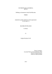
10 REQUEST FOR SPARE PARTS
How to order the spare parts::
a) The model of the pump.( MOD. )
b) The serial number of the pump ;
See pump label
c) The denomination of the part.;
d) The number of pieces.;
e) The code of the part.;
See spare parts list
Esempio:
a) VL 14 Ex
b) X50012
c) End lobe
d) n° 4 pieces
e) 1503601400