1
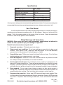
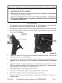
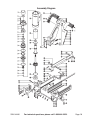
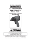
®
2 in 1 Flooring Cleat/
Staple Nailer
Model 94446
ASSEMBLY and OPERATING
INSTRUCTIONS
®
3491 Mission Oaks Blvd., Camarillo, CA 93011
Visit our Web site at http://www.harborfreight.com
Copyright© 2006 by Harbor Freight Tools®. All rights reserved. No portion of
this manual or any artwork contained herein may be reproduced in any shape
or form without the express written consent of Harbor Freight Tools.
For technical questions and replacement parts, please call 1-800-444-3353
Specifications
Air Inlet
Working Air Pressure
Maximum Air Pressure
Magazine Capacity
Air Consumption
Cleat Size Range
Staple Size Range
1/4”- 18 NPT
60-125 PSI
125 PSI *
80
4 CFM @ 125 PSI
1-1/2” to 2” L-head Nails
1” to 2” Flooring Staples
* The air pressure setting must not exceed job site regulations/restrictions. The air pressure setting must
not exceed 90 PSI when being used with work pieces that have a thickness of less than 1-3/4”.
Save This Manual
You will need the manual for the safety warnings and precautions, assembly instructions,
operating and maintenance procedures, parts list and diagram. Keep your invoice with this
manual. Write the invoice number on the inside of the front cover. Keep the manual and
invoice in a safe and dry place for future reference.
Safety Warnings and Precautions
WARNING: When using tool, basic safety precautions should always be followed to
reduce the risk of personal injury and damage to equipment.
Read all instructions before using this tool!
1.
Keep work area clean. Cluttered areas invite injuries.
2.
Observe work area conditions. Do not use machines or power tools in damp or wet
locations. Don’t expose to rain. Keep work area well lighted. Do not use electrically
powered tools in the presence of flammable gases or liquids.
3.
Keep children away. Children must never be allowed in the work area. Do not let them
handle machines, tools, extension cords, or air hoses.
4.
Store idle equipment. When not in use, tools must be stored in a dry location to inhibit
rust. Always lock up tools and keep out of reach of children.
5.
Use the right tool for the job. Do not attempt to force a small tool or attachment to do
the work of a larger industrial tool. There are certain applications for which this tool was
designed. It will do the job better and more safely at the rate for which it was intended. Do
not modify this tool and do not use this tool for a purpose for which it was not intended.
6.
Dress properly. Do not wear loose clothing or jewelry as they can be caught in
moving parts. Protective, electrically nonconductive clothes and nonskid footwear are
recommended when working. Wear restrictive hair covering to contain long hair.
7.
Use eye and ear protection. Always wear ANSI-approved impact safety goggles. Wear
a full face shield if you are producing metal filings or wood chips. Wear an ANSI-approved
dust mask or respirator when working around metal, wood, and chemical dusts and
mists.
REV 11/06
SKU 94446
For technical questions, please call 1-800-444-3353.
Page 8.
Do not overreach. Keep proper footing and balance at all times. Do not reach over or
across running machines or air hoses.
9.
Maintain tools with care. Keep tools clean for better and safer performance. Follow
instructions for lubricating and changing accessories. Inspect tool cords and air hoses
periodically and, if damaged, have them repaired by a qualified technician. The handles
must be kept clean, dry, and free from oil and grease at all times.
10. Disconnect air supply. Disconnect air hose when not in use.
11. Remove adjusting keys and wrenches. Check that keys and adjusting wrenches are
removed from the tool or machine work surface before plugging it in.
12. Avoid unintentional starting. Do not carry any tool while holding the trigger, whether
it is plugged in or not.
13. Stay alert. Watch what you are doing, use common sense. Do not operate any tool
when you are tired.
14. Check for damaged parts. Before using any tool, any part that appears damaged
should be carefully checked to determine that it will operate properly and perform its
intended function. Check for alignment and binding of moving parts; any broken parts
or mounting fixtures; and any other condition that may affect proper operation. Any part
that is damaged should be properly repaired or replaced by a qualified technician. Do
not use the tool if any switch does not turn On and Off properly.
15. Guard against electric shock. Prevent body contact with grounded surfaces such as
pipes, radiators, ranges, and refrigerator enclosures.
16. Replacement parts and accessories. When servicing, use only identical replacement
parts. Use of any other parts will void the warranty. Only use accessories intended for
use with this tool. Approved accessories are available from Harbor Freight Tools.
17. Do not operate tool if under the influence of alcohol or drugs. Read warning labels
if taking prescription medicine to determine if your judgement or reflexes are impaired
while taking drugs. If there is any doubt, do not operate the tool.
18. Use proper size and type extension cord. If an extension cord is required for the air
compressor, it must be of the proper size and type to supply the correct current to the
tool without heating up. Otherwise, the extension cord could melt and catch fire, or cause
electrical damage to the tool. Check your compressor’s manual for the appropriate size
cord.
Note: Performance of the compressor (if powered by line voltage) may vary depending on
variations in local line voltage. Extension cord usage may also affect tool performance.
19. Maintenance. For your safety, maintenance should be performed regularly by a qualified
technician.
20. Compressed air only. Never use combustible gases as a power source.
Warning: The warnings, cautions, and instructions discussed in this instruction
manual cannot cover all possible conditions and situations that may occur. It must be
understood by the operator that common sense and caution are factors which cannot
be built into this product, but must be supplied by the operator.
SKU 94446
For technical questions, please call 1-800-444-3353.
Page Unpacking
When unpacking, check to make sure the item is intact and undamaged. If any parts are
missing or broken, please call Harbor Freight Tools at the number on the cover of this
manual as soon as possible.
Setup
Floor
Stapler
1/4”-18 NPT
For best service you should incorporate an oiler, regulator, and inline filter, as shown in the
diagram above. Hoses, couplers, oilers, regulators, and filters are all available at Harbor
Freight Tools.
1.
Wrap the Air Inlet (37) with pipe thread seal tape (not included) before threading it into
the Arm (30). Connect the 3/8” ID Air Source Hose to the Air Inlet (37).
Note: If you are not using an automatic oiler system, before each use add a few drops of
Pneumatic Tool Oil to the airline connection. Add a few drops more after each hour of
continual use.
2.
Set the air pressure on your compressor to between 60-125 PSI. Do not exceed the
maximum air pressure of 125 PSI.
3.
Check the air connection for leaks. Disconnect from the air source.
REV 11/06
SKU 94446
For technical questions, please call 1-800-444-3353.
Page Loading the Tool
Warning! Disconnect the Stapler from the air compressor whenever loading or servicing. After
disconnecting the Stapler from the air compressor, there could still be enough air pressure to
fire the Stapler. After the air compressor hose is disconnected, always fire the Stapler into a
piece of scrap to make sure all of the air is expended.
1.
Grip the Sleeve (78) and pull out the Magazine Cover (72).
Caution: The Magazine Cover (72) may snap closed with force, sometimes without
warning.
Cleats
FIGURE 1
2.
Install fasteners:
Cleats – Place the Cleats into the larger slot in the magazine so that the top of the cleat
rests on the rail in the center of the magazine. See Figure 1, above.
Staples – Place the staples over the center rail of the magazine.
Note: Only use the fastener types and sizes listed on the Specifications Chart on page 2.
3.
While holding the Sleeve (78) securely, slide the Magazine Cover (72) closed.
SKU 94446
For technical questions, please call 1-800-444-3353.
Page Operation
1.
Connect the Floor Stapler to the air hose and turn on the air compressor.
Note: Before using on a floor, test the unit on a scrap piece of wood. Adjust the driving depth
by providing more or less air pressure. Never exceed 125 PSI.
Warning! Keep your feet clear of the Stapler. Refer to Figure 2.
2.
Hold the Handle (44) securely with one hand and grip the Hammer with the other
hand.
FIGURE 2
Trigger (33)
(This helps prevent
unintentional firing.)
FIGURE 3
Hammer
Face (1)
(Striking this with the
Trigger (33) held causes
the stapler to fire.)
Fasteners exit the Stapler from the bottom in the
direction indicated above.
3.
Make sure the Base Plate (52) is over the Fastener target position. Press down hard
so that the Base Plate (52) is firmly contacting the floor. Then squeeze the Trigger (33)
and strike the Hammer Face (1) with the Hammer to drive out a Fastener. Lift the tool
off of the floor. See Figure 3.
4.
Repeat the process until you are finished. Then, disconnect the Floor Stapler from the
air source.
Warning! After disconnecting the Stapler from the air compressor, there could still be enough
air pressure to fire the Stapler. After the air compressor hose is disconnected, always
fire the Stapler into a piece of scrap to make sure all of the air is expended.
REV 11/06
SKU 94446
For technical questions, please call 1-800-444-3353.
Page Anytime any maintenance or repairs are done (including clearing jams), first:
1.
2.
3.
4.
Disconnect the Stapler from the air hose.
Empty Magazine (59, 69) completely.
Attempt to fire the Stapler into a piece of scrap wood to ensure that it is disconnected
and is incapable of firing any Fasteners.
Always leave Magazine Cover (72) closed during maintenance. The Magazine
Cover is spring-loaded and may cause parts or a Fastener to fly out of the Stapler
if it suddenly snaps closed.
Clearing Jams
1.
Disconnect tool from air hose, empty Magazine (59, 69) of Fasteners, release any builtup air pressure, and keep the magazine closed, as explained above.
2.
While doing this step and the next, hold the Stapler pointed away from you and any other
people or fragile objects. Remove all three Screws (49) and Washers (4) on the Driver
Cover (48). See Figure 4.
FIGURE 4
Driver
Blade
FIGURE 5
3.
Carefully lift the Driver Cover (48) off and remove the jammed Fastener. Pliers may be
necessary to remove a stuck Fastener.
4.
Inspect the Driver on the end of the Piston Assembly (26) for bends or breakage. If it is
damaged, do not use the tool until it is repaired by a qualified technician. See Figure
5.
5.
Lightly oil the driver and replace the Driver Cover (48). Make sure that the Driver Cover
(48) fits in place flush and that the Driver does not get pinched by it. Replace and securely tighten all of the Screws (49) and Washers (4).
6.
Reload the Stapler and reconnect it to the air hose.
7.
Press the tip of the Stapler against an appropriate piece of scrap wood.
8.
Test fire the Stapler several times, checking for proper operation.
9.
Disconnect the Stapler, remove the Fasteners, and store the Stapler in a location out of
children’s reach.
SKU 94446
For technical questions, please call 1-800-444-3353.
Page Anytime any maintenance or repairs are done, first:
1.
Disconnect the Stapler from the air hose.
2.
Empty Magazine (59, 69) completely.
3.
Attempt to fire the Stapler into a piece of scrap wood to ensure that it is disconnected
and is incapable of firing any Fasteners.
4.
Always leave Magazine Cover (72) closed during maintenance. The Magazine
Cover is spring-loaded and may cause parts or a Fastener to fly out of the Stapler
if it suddenly snaps closed.
Maintenance
1.
2.
3.
Periodically lubricate all moving parts and pivots with a light oil.
Wipe down the Floor Stapler with a damp cloth. Do not use harsh detergents or
solvents.
Check that the Base Plate (52) and the Hammer Face (1) is clear of any dirt or
debris.
Troubleshooting
Note: Have the following problems repaired by a qualified service technician.
PROBLEM
CAUSE
SOLUTION
Air leaking in nose
1. Loose Nose Screws
2. Bumper is cracked/worn
1. Tighten and recheck
2. Replace Bumper
Lack of Power, slow to cycle.
1. Tool is too dry
2. Air Pressure is too low
3. Exhaust blocked
1. Lubricate
2. Check air supply equipment
3. Clean exhaust channel
Intermittent feeding or no fastener 1. Damaged pusher spring
coming out
2. Wrong size Fastener
3. Dirty magazine or wearplate
1. Replace Spring
2. Use correct size
3. Clean magazine and nose
Jammed Fastener
1. Replace wear plate
2. Replace driver
3. Use straight Fasteners
1. Driver channel worn
2. Driver is broken/worn
3. Bent Fasteners
PLEASE READ THE FOLLOWING CAREFULLY
THE MANUFACTURER AND/OR DISTRIBUTOR HAS PROVIDED THE PARTS DIAGRAM IN THIS MANUAL
AS A REFERENCE TOOL ONLY. NEITHER THE MANUFACTURER NOR DISTRIBUTOR MAKES ANY
REPRESENTATION OR WARRANTY OF ANY KIND TO THE BUYER THAT HE OR SHE IS QUALIFIED TO
MAKE ANY REPAIRS TO THE PRODUCT OR THAT HE OR SHE IS QUALIFIED TO REPLACE ANY PARTS
OF THE PRODUCT. IN FACT, THE MANUFACTURER AND/OR DISTRIBUTOR EXPRESSLY STATES THAT
ALL REPAIRS AND PARTS REPLACEMENTS SHOULD BE UNDERTAKEN BY CERTIFIED AND LICENSED
TECHNICIANS AND NOT BY THE BUYER. THE BUYER ASSUMES ALL RISK AND LIABILITY ARISING
OUT OF HIS OR HER REPAIRS TO THE ORIGINAL PRODUCT OR REPLACEMENT PARTS THERETO,
OR ARISING OUT OF HIS OR HER INSTALLATION OF REPLACEMENT PARTS THERETO.
SKU 94446
For technical questions, please call 1-800-444-3353.
Page Parts List
Part
Description
Part
Description
Part
Description
1
Hammer Face
28
Bumper
55
Washer
2
O-ring 30.3 x 2.65
29
Seal
56
Coil Spring
3
Screw
30
Arm
57
Spring Bracket
4
Spring Washer
31
Handle A
58
Screw
5
Cylinder Cap
32
Locknut
59
Magazine A
6
Screw
33
Trigger
60
Washer
7
Spring Washer
34
Sleeve
61
Screw
8
Actuator A
35
Pin
62
Screw
9
Snap Ring
36
Pin
63
Plate
10
Half Block
37
Air Inlet
64
Limit Nut
11
Bushing
38
Spring
65
Support Plate A
12
O-ring 33.3 x 2.65
39
Trigger Valve Stem
66
Screw
13
Actuator B
40
O-ring 6.4 x 1.8
67
Spring Washer
14
O-ring 57.4 x 3.5
41
O-ring 11 x 1.4
68
Screw
15
Retaining Ring
42
Trigger Valve Guide
69
Magazine B
16
Poppet Cap
43
Screw
70
Bushing
17
O-ring 42 x 3.5
44
Handle B
71
Pin
18
Plunger
45
Screw
72
Magazine Cover
19
O-ring 21 x 2
46
Guide Body
73
Feeder
20
O-ring 14.3 x 2.5
47
Pin
74
Nut
21
Body
48
Driver Cover
75
Rail A
22
Cylinder
49
Screw
76
Orienting Plate
23
O-ring 17.5 x 2.6
50
Pin
77
Rail B
24
O-ring 38.5 x 4.5
51
Plate
78
Sleeve
25
Poppet
52
Base Plate
79
Screw
26
Piston Assembly
53
Screw
80
Support Plate B
27
O-ring 58.7 x 3.5
54
Pad
81
Magazine Handle
SKU 94446
For technical questions, please call 1-800-444-3353.
Page Assembly Diagram
SKU 94446
For technical questions, please call 1-800-444-3353.
Page 10
SKU 94446
For technical questions, please call 1-800-444-3353.
Page 11