1
User's Guide
TI FEE Driver User Guide
Read This First
IMPORTANT NOTICE
Texas Instruments and its subsidiaries (TI) reserve the right to make changes to their products or to
discontinue any product or service without notice, and advise customers to obtain the latest version of
relevant information to verify, before placing orders, that information being relied on is current and
complete. All products are sold subject to the terms and conditions of sale supplied at the time of order
acknowledgment, including those pertaining to warranty, patent infringement, and limitation of liability.
TI warrants performance of its products to the specifications applicable at the time of sale in
accordance with TI’s standard warranty. Testing and other quality control techniques are utilized to the
extent TI deems necessary to support this warranty. Specific testing of all parameters of each device is
not necessarily performed, except those mandated by government requirements.
Customers are responsible for their applications using TI components.
In order to minimize risks associated with the customer’s applications, adequate design and operating
safeguards ought to be provided by the customer so as to minimize inherent or procedural hazards.
TI assumes no liability for applications assistance or customer product design. TI does not warrant or
represent that any license, either express or implied, is granted under any patent right, copyright, mask
work right, or other intellectual property right of TI covering or relating to any combination, machine, or
process in which such products or services might be or are used. TI’s publication of information
regarding any third party’s products or services does not constitute TI’s approval, license, warranty or
endorsement thereof.
Reproduction of information in TI data books or data sheets is permissible only if reproduction is without
alteration and is accompanied by all associated warranties, conditions, limitations and notices.
Representation or reproduction of this information with alteration voids all warranties provided for an
associated TI product or service is an unfair and deceptive business practice, and TI is neither
responsible nor liable for any such use.
Resale of TI’s products or services with statements different from or beyond the parameters stated by
TI for that product or service voids all express and any implied warranties for the associated TI product
or service, is an unfair and deceptive business practice, and TI is not responsible nor liable for any such
use.
Also see: Standard Terms
www.ti.com/sc/docs/stdterms.htm
and
Conditions
of
Sale
for
Semiconductor
Mailing Address:
Texas Instruments
Post Office Box 655303
Dallas, Texas 75265
Copyright © 2012, Texas Instruments Incorporated
2
Products.
Preface
Read This First
About This Manual
This User’s Manual serves as a software programmer’s handbook for
working with the TI FEE Driver. It provides necessary information regarding
how to effectively install, build and use TI FEE Driver in user systems and
applications.
It also provides details regarding the TI FEE Driver functionality, the
requirements it places on the hardware and software environment where it
can be deployed, how to customize/ configure it etc. It also provides
supplementary information regarding steps to be followed for proper
installation/ un-installation of the TI FEE Driver.
Abbreviations
1-1. Table of Abbreviations
Abbreviation
Description
TI FEE Driver
This is TI coined name for the product.
FEE
Flash EEPROM Emulation
3
Read This First
Revision History
Version
Date
Revision History
1.0
09/25/2012
1.1
11/12/2012
Initial version
4
Contents
Read This First ................................................................................................................. 3
Contents ............................................................................................................................ 5
Table of tables .................................................................................................................. 7
Table of figures ................................................................................................................. 8
Chapter 1 .......................................................................................................................... 9
TI FEE Driver Introduction ............................................................................................ 9
1.1
OVERVIEW ........................................................................................................ 10
1.1.1 Functions supported in the TI FEE Driver .................................................... 10
1.1.2 Other Components ........................................................................................ 11
1.1.3 Development Platform .................................................................................. 11
Chapter 2 ........................................................................................................................ 12
TI FEE Driver Design Overview ................................................................................... 12
OVERVIEW .................................................................................................................... 12
2.1
FLASH EEPROM EMULATION METHODOLOGY .................................................. 13
2.1.1 Virtual Sector Organization .......................................................................... 13
2.1.2 Data Block Organization............................................................................... 16
2.1.3 Supported Commands .................................................................................. 18
2.1.4 Status Codes ................................................................................................. 18
2.1.5 Job Result ..................................................................................................... 18
Chapter 3 ........................................................................................................................ 19
File List ........................................................................................................................... 19
Chapter 4 ........................................................................................................................ 21
4.1
ERROR RECOVERY IMPLEMENTATION................................................................. 21
4.2
SINGLE AND DOUBLE BIT ERROR CORRECTIONS ................................................. 22
4.3
MEMORY MAPPING ........................................................................................... 22
4.4
BUILD PROCEDURE ............................................................................................ 23
4.5
SYMBOLIC CONSTANTS AND ENUMERATED DATA TYPES .................................... 24
4.6
DATA STRUCTURES............................................................................................ 26
4.7.1 Operating Frequency .................................................................................... 27
4.7.2 Number of Blocks .......................................................................................... 28
4.7.3 Number of Virtual Sectors ............................................................................. 28
4.7.4 Number of Virtual Sectors for EEP1.............................................................. 28
5
Contents
4.7.5 TI FEE Virtual Sector Configuration ............................................................. 29
4.7.6 TI FEE Block Configuration .......................................................................... 31
4.7.7 Block OverHead ............................................................................................ 34
4.7.8 Page OverHead ............................................................................................ 35
4.7.9 Virtual Sector OverHead .............................................................................. 35
4.7.10 Virtual Sector Page Size ........................................................................... 35
4.7.11 Driver Index .............................................................................................. 36
4.7.12 Enable ECC Correction............................................................................. 36
4.7.13 Error Correction Handling ........................................................................ 36
4.7.14 Block Write Counter Save .......................................................................... 37
4.7.15 Enable CRC .............................................................................................. 37
4.7.16 NumberOfEEPs ......................................................................................... 37
4.8
API CLASSIFICATION ......................................................................................... 38
4.8.1 Initialization.................................................................................................. 38
4.8.2 Data Operations............................................................................................ 38
4.8.3 Information ................................................................................................... 39
4.8.4 Internal Operations ....................................................................................... 39
4.8.5 Error Information and Recovery Operations ................................................. 39
4.9
FEE OPERATION FLOW ....................................................................................... 40
4.10 API SPECIFICATION ........................................................................................... 41
4.10.1 TI FEE Driver Functions ........................................................................... 41
4.11 PRIVILEGE MODE ACCESS................................................................................... 48
6
Table of tables
1-1. Table of Abbreviations ............................................................................................. 3
Revision History ............................................................................................................... 4
2-1. Virtual Sector Header States ................................................................................. 15
2-2. Data Block Header Field Definitions ..................................................................... 17
2-3. Data Block States.................................................................................................... 17
3-2. TI FEE Driver File List .......................................................................................... 19
3-3. TI FEE HALCoGen™ File List ............................................................................. 20
4-1. TI FEE Driver Symbolic Constants ....................................................................... 26
4-2. TI FEE Driver Published Information Data Structure ........................................ 26
4-3. TI FEE Driver General Configuration Data Structure ........................................ 27
4-4. TI FEE Driver Initialization APIs ......................................................................... 38
4-5. TI FEE Driver Data Operation APIs .................................................................... 38
4-6. TI FEE Driver Information APIs .......................................................................... 39
4-7. TI FEE Driver Internal Operation APIs ............................................................... 39
4-8. TI FEE Driver Error Info and Recovery APIs ..................................................... 39
7
Table of figures
Table of figures
FIGURE 1 VIRTUAL SECTOR ORGANIZATION....................................................................... 14
FIGURE 2 VIRTUAL SECTOR HEADER ................................................................................. 15
FIGURE 3 DATA BLOCK STRUCTURE .................................................................................. 16
FIGURE 4 DATA BLOCK HEADER -> LOGICAL STRUCTURE .................................................. 16
FIGURE 5 VIEW GRAPH OF TI FEE DRIVER DIRECTORY TREE ........ ERROR! BOOKMARK NOT
DEFINED.
FIGURE 6 FLOW CHART OF A TYPICAL FEE OPERATION ....................................................... 40
8
Chapter 1
TI FEE Driver Introduction
This chapter introduces the TI FEE Driver to the user by providing a brief
overview of the purpose and construction of the TI FEE Driver along with
hardware and software environment specifics in the context of TI FEE
Driver deployment.
9
1.1 Overview
This section describes the functional scope of the TI FEE Driver and its
feature set. It introduces the TI FEE Driver to the user along with the
functional decomposition and run-time specifics regarding deployment of TI
FEE Driver in user’s application.
Many applications require storing small quantities of system related data
(e.g., calibration values, device configuration) in a non-volatile memory, so
that it can be used, modified or reused even after power cycling the
system. EEPROMs are primarily used for this purpose. EEPROMs have
the ability to erase and write individual bytes of memory many times over
and the programmed locations retain the data over a long period even
when the system is powered down.
The objective of TI FEE Driver is to provide a set of software functions
intended to use a Sector of on-chip Flash memory as the emulated
EEPROM. These software functions are transparently used by the
application program for writing, reading and modifying the data.
A list of functions supported by the TI FEE Driver can be found in
Section 1.1.1. The primary function responsible for Fee management is
the TI_FeeManager function. This function shall operate asynchronously
and with little or no user intervention after configuration, maintaining the
Fee structures in Flash memory. This function should be called on a cyclic
basis when no other pending Fee operations are pending so that it can
perform internal operations.
1.1.1
Functions supported in the TI FEE Driver
The TI FEE Driver provides the following functional services:
Initialization:
TI_Fee_Init
Operations:
TI_Fee_WriteAsync
TI_Fee_WriteSync
TI_Fee_Read
TI_Fee_EraseImmediateBlock
TI_Fee_InvalidateBlock
TI_Fee_Shutdown
TI_Fee_Cancel
TI_Fee_Format
Information:
TI_FEE_getStatus
TI_FEE_getJobResult
10
TI_FEE_getVersionInfo
Internal Operations:
TI_Fee_MainFunction
TI_FeeInternal_FeeManager
Error Information and Recovery:
TI_FeeErrorCode
TI_Fee_ErrorRecovery
1.1.2
Other Components
The TI FEE Driver requires the following components for complete
deployment.
1. TI Fee Configuration Files :
The user needs to generate the following two configuration files using
HALCoGen to deploy and use TI FEE Driver.
a. TI_fee_cfg.h
b. TI_fee_cfg.c
These two files define which Flash sectors to be used for EEPROM
emulation, define Data Blocks ,Block Size and other configuration
parameters.
HALCoGen also generates device specific files that defines the
memory mapping for the Flash FEE bank.
2. Flash API library :
The TI FEE Driver uses the Flash API library for performing
program/erase operations. The
apprioprate Flash API library
depending on the type of Flash technology has to be included in the
application to deploy and use the TI FEE Driver. F021 version should
be 2.0.0 of greater.
1.1.3
Development Platform
The TI FEE Driver was developed and validated on a system with the
following operating system and software installed
Operating System : Win7
Codegeneration tools : TMS570 Code Generation tools 4.9.5
11
Chapter 2
TI FEE Driver Design
Overview
Overview
This chapter describes the implementation method followed for Flash
EEPROM emulation in the TI FEE Driver.
12
2.1 Flash EEPROM Emulation Methodology
The EEPROM Emulation Flash bank is divided into two or more Virtual
Sectors. Each Virtual Sector is further partitioned into several Data Blocks.
A minimum of two Virtual Sectors are required for Flash EEPROM
emulation.
The initialization routine (TI_Fee_Init) identifies which Virtual Sector to be
used and marks it as Active. The data is written to the first empty location
in the Active Virtual Sector. If there is insufficient space in the current
Virtual Sector to update the data, it switches over to the next Virtual Sector
and copies all the valid data from the other Data Blocks in the current
Virtual Sector to the new one. After copying all the valid data, the current
Virtual Sector is erased and the new one is marked as Active Virtual
Sector. Any new data is now written into the new Active Virtual Sector and
the erased Virtual Sector is used again once this new Virtual Sector has
insufficient space.
Virtual Sectors and Data Blocks have certain space allocated to maintain
the status information which is described in more detail in the following
sections.
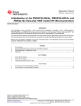
2.1.1
Virtual Sector Organization
The Virtual Sector is the basic organizational unit used to partition the
EEPROM Emulation Flash Bank. This structure can contain one or more
contiguous Flash Sectors contained within one Flash Bank. A minimum of
2 Virtual Sectors are required to support the TI FEE Driver.
The internal structure of the Virtual Sector contains a Virtual Sector
Header, a static Data Structure and the remaining space is used for Data
Blocks.
13
Virtual Sector Organization
Virtual Sector Header
Block 3
… Block n
Block 5 DS4
Block n
Block 3
Block 3
Block 5 DS3
Block 0
Block 1 DS2
Block 3
Block 2
Block 5 DS4
Virtual
Sector
0
Block X
Block X
Block X
Block X
Block n
Block X
Block 3
Block 5 DS3
Block 2
Block n
Virtual Sector Header
Block n
… Block 3
Block5 DS3
Block 1 DS2
Block 2
Block n
Block 5 DS4
Block 5 DS3
Block X
Block X
Block X
Block X
Block X
Block X
Figure 1 Virtual Sector Organization
14
Virtual
Sector
1
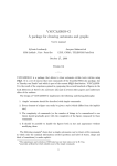
2.1.1.1
Virtual Sector Header
The Virtual Sector Header consists of two 64bit words (16 bytes) that
start at the first address of a Virtual Sector Structure. The state of the
Virtual Sector Structure is maintained in the Virtual Sector Header.
64 bit Status Word
40 bits Reserved
Erase Count
(20 bits)
Version Number
(4 Bits)
Figure 2 Virtual Sector Header
The Status Word is the first 64 bit word of the Virtual Sector Header
and is used to indicate the current state of the Virtual Sector.
The following table indicates the various states a Virtual Sector can be
in.
State
Value
Invalid Virtual Sector
0xFFFFFFFFFFFFFFFF
Empty Virtual Sector
0x0000FFFFFFFFFFFF
Copy Virtual Sector
0x00000000FFFFFFFF
Active Virtual Sector
0x000000000000FFFF
Ready for Erase
0x0000000000000000
2-1. Virtual Sector Header States
Invalid Virtual Sector: This Virtual Sector is either in process of being
erased or has not yet been initialized.
Empty Virtual Sector: This indicates the Virtual Sector has been
erased and can be used to store data.
Copy Virtual Sector: This indicates that the Data Block Structure is
being moved from a full Virtual Sector to this one to allow for moving of
the Active Virtual Sector.
Active Virtual Sector: This Virtual Sector is the active one.
Ready for Erase: This Virtual Sector’s Data Block Structure has been
correctly replicated to a new Virtual Sector and is now ready to be
erased and initialized for re-use.
Virtual Sector Information Record is the second 64 bit word in the Virtual
Sector header. It is used to record information needed by the Virtual Sector
management algorithm. Currently the first 4 bits are used to indicate the
current version of the Virtual Sector and the next 20 bits are used to
indicate the number of times the Virtual Sector has been erased. The erase
count is incremented each time the Virtual Sector is erased. The remaining
bits are reserved for future use
15
2.1.2
Data Block Organization
The Data Block is used to define where the data within a Virtual Sector
is mapped. One or more variables can be within a Data Block based
on the user definition. The smallest amount of data that can be stored
within the Data Block is 64 bits. If the Data size exceeds 64 bits, the
Data Packets are added in 64 bit increments. The Data Block
Structure is limited to the size of the Virtual Sector it resides in.
Note: The size of all the Data Blocks cannot exceed the Virtual
Sector length.
When a Data Packet write exceeds the available space of the current
Virtual Sector, the Data Block structure is duplicated in the next Virtual
Sector to be made active.
Data Block Structure
Block5
Header
Block4
Header
Dataset2
Dataset4
Block5
Header
Block2
Header
Dataset6
Block1
Header
Block1
Header
Dataset2
Dataset2
Dataset8
Block3
Header
Block2
Header
Dataset1
Dataset3
Figure 3 Data Block Structure
2.1.2.1
Data Block Header
The Data Block Header is 8 bytes in length and is used to indicate the
location information (address) of valid data within a Virtual Sector.
Block Number (16 bits)
Block size(16 bits)
Block W/E Cycle count - optional (32 bits) / reserved if saving not enabled
CRC - optional (32 bits)
Address of previous Valid Block(32 bits)
Block Status (64 bits)
Figure 4 Data Block Header -> Logical Structure
16
Bit(s)
191-176
175-160
159-128
127-96
95-64
63-0
A Standard Data Block Header has the following fields
Field
Description
Block Number
This is used to indicate the block number.
Block size
Indicates size of block
W/E counter
Indicates write/erase counter for a block
CRC
Indicates CRC of block
Address
Address of the previous valid block
Status of the
Block
These 64 bits indicate the Status of the Block. The
following Table lists all the possible combinations for the
Block Status.
2-2. Data Block Header Field Definitions
State
Value
Empty Block
0xFFFFFFFFFFFFFFFF
Start Program Block
0xFFFFFFFFFFFF0000
Valid Block
0xFFFFFFFF00000000
Invalid Block
0xFFFF000000000000
Corrupt Block
0x0000000000000000
2-3. Data Block States
Block Status is used to ensure that data integrity is maintained even if the Block (data)
update process is interrupted by an uncontrolled event such as a power supply failure or
reset.
Empty Block: New Data can be written to this Block.
Start Program Block: This indicates that the Data Block is in the progress of being
programmed with data.
Valid Block: This indicates that the Data Block is fully programmed and contains Valid
Data.
Invalid Block: This indicates that the Data Block contains invalid or old data.
Corrupt Block: This indicates that the Data Block is corrupted and the Software should
ignore this Block.
17
2.1.3
Supported Commands
The following list describes the supported commands.
1. WriteAsync: This command shall program a Flash Data block
asynchronously.
2. WriteSync: This command shall program a Flash Data block
synchronously.
3. Read: This command shall copy a continuous Flash Data block.
4. Erase: This command will erase a Flash Data block. It will update
the address field in the Data Block to point to a location which is
blank (all 1’s).
5. Invalidate Block: This command shall mark the block as invalid in
Data Block header.
2.1.4
Status Codes
This indicates the status of the Fee module. It can be in one of the
following states
1. Uninitialized: The Fee Module has not been initialized.
2. Idle: The Fee Module is currently idle.
3. Busy: The Fee Module is currently busy.
4. Busy Internal: The Fee Module is currently busy with internal
management operations.
2.1.5
Job Result
This indicates the result of the last job. The job result can be any one of
the following states
1. OK:
The last job has finished successfully
2. Pending: The last job is waiting for execution or is currently being
executed.
3. Cancel:
The last job has been cancelled.
4. Failed:
The last read/erase/write job failed.
5. Inconsistent: The requested block is inconsistent, it may contain
corrupted data.
6. Invalid:
The requested block has been invalidated. The
requested read operation cannot be performed.
18
Chapter 3
File List
This chapter provides the list of files generated from HALCoGen for TI FEE
Driver.
File Name
Destination directory
ti_fee.h
Include
tiI_fee_Types.h
Include
ti_fee_utils.c
Source
ti_fee_EraseImmediateBlock.c
Source
ti_fee_Format.c
Source
ti_fee_Info.c
Source
ti_fee_InvalidateBlock.c
Source
ti_fee_cancel.c
Source
ti_fee_Read.c
Source
ti_fee_Shutdown.c
Source
ti_fee_ini.c
Source
ti_fee_Main.c
Source
ti_fee_WriteAsync.c
Source
ti_fee_WriteSync.c
Source
fee_interface.h
Include
3-2. TI FEE Driver File List
Files generated using HALCoGen™ are listed below
File Name
Destination directory
device_types.h
Include
Device_header.h
Include
19
TI_fee_cfg.h
Include
TI_fee_cfg.c
Source
Device_TMS570LS31.h
Include
Device_TMS570LS31.c
Source
3-3. TI FEE HALCoGen™ File List
Note: xx indicates device part number
E.g.: If the target device chosen is TMS570LS31, then the device specific
files generated are Device_TMS570LS31.h and Device_TMS570LS31.c
20
Chapter 4
Integration Guide
This chapter describes the steps for using the TI FEE Driver. This chapter
also discusses the TI FEE Driver run-time interfaces that comprise the API
classification, usage scenarios and the API specification. The entire source
code to implement the TI FEE Driver is included in the delivered product.
4.1 Error Recovery Implementation
Projects should implement error recovery mechanism to recover from serious errors. They
should call the API TI_FeeErrorCode( ) periodically to check if there are any severe
errors(Error_TwoActiveVS, Error_TwoCopyVS, Error_SetupStateMachine, Error_NoActiveVS,
Error_CopyButNoActiveVS, Error_NoFreeVS, Error_EraseVS). If error is any of the above type,
then API TI_Fee_ErrorRecovery( ) should be called with proper parameters.
If the error is of type Error_TwoActiveVS or Error_TwoCopyVS or
Error_CopyButNoActiveVS, then the application has to provide info on which of the VS needs to be
corrected in u8VirtualSector. TI_Fee_u16ActCpyVS will provide info on which of the VS’s are
Active/Copy. For error of type Error_CopyButNoActiveVS, TI_Fee_u16ActCpyVS will provide info
on which VS is Copy. In this case, the second argument for the TI_Fee_ErrorRecovery should be
the copy VS number. Error recovery API will mark the VS as Active.
If the error is of type Error_NoFreeVS, then the application has to provide info on which of
the VS needs to be erased in u8VirtualSector. TI_Fee_u16ActCpyVS will provide info on which VS
is active.
If the error is of type Error_SetupStateMachine, recheck configuration. Configure RWAIT,
EWAIT and operating frequency correctly.
If the error is of type Error_EraseVS, this means either erasing or a blank check of VS failed.
Call error recovery function to perform erase again. Check the variables
TI_Fee_GlobalVariables[u8EEPIndex].Fee_u16ActiveVirtualSector /
TI_Fee_GlobalVariables[u8EEPIndex].Fee_u16CopyVirtualSector to know which of the VS’s are
active/copy. Erase other sectors.
Application can access the variable “TI_Fee_u16ActCpyVS” to know details about the VS’s.
Prototype for the API’s are:
TI_Fee_ErrorCodeType TI_FeeErrorCode(uint8 u8EEPIndex);
void TI_Fee_ErrorRecovery(TI_Fee_ErrorCodeType ErrorCode, uint8 u8VirtualSector);
If two EEPROM’s are configured, then TI_FeeErrorCode has to be called cyclically with
different index.
Ex: TI_FeeErrorCode(0) and TI_FeeErrorCode(1)
21
If Error is of type Error_TwoActiveVS and TI_Fee_u16ActCpyVS = 0x0003, this means VS 1
and 2 are Active.
If projects want to make VS 1 as Active, then
Call TI_Fee_ErrorRecovery(Error_TwoActiveVS, 2);
Virtual sector 2 will be marked as Ready for Erase.
Virtual sector numbers start from 1.
4.2 Single and Double bit Error Corrections
FEE software provides a mechanism to detect single and double bit errors. In order to use
this feature, application has to make sure that “EE_EDACMODE[3:0]: Error Correction Mode”
in “EE_CTRL1” should be set to a value other than 0101, “EE_ONE_EN: Error on One Fail
Enable” should be enabled, “EE_ZERO_EN: Error on Zero Fail Enable” should be enabled,
“EE_EDACEN[3:0]: Error Detection and Correction Enable” should be set to a value other
than 0101.
Projects have to then call error hook functions TI_Fee_ErrorHookSingleBitError( ) and
TI_Fee_ErrorHookDoubleBitError( ) in ESM. For single bit error, an event is generated on
channel 35 of ESM and for double bit error on channel 36 of ESM.
4.3 Memory Mapping
Following macros can be used for reallocating code, constants and variables.
FEE_START_SEC_CONST_UNSPECIFIED
FEE_STOP_SEC_CONST_UNSPECIFIED
FEE_START_SEC_CODE
FEE_STOP_SEC_CODE
FEE_START_SEC_VAR_INIT_UNSPECIFIED
FEE_STOP_SEC_VAR_INIT_UNSPECIFIED
.
22
4.4 Build Procedure
The build procedure mentions how one ought to go about building the TI
FEE Driver into their systems and applications.
1. The driver files generated from HALCoGen should be included in the
application.
2.
The files listed in Table 3.3 (Fee configuration files and device specific
files) generated using HALCoGen™ should be included in the
application. The configuration files (ti_fee_cfg.h & ti_fee_cfg.c) define
which Flash sectors to be used for EEPROM emulation, define Data
Blocks, Block Size and other configuration parameters whereas the
device specific files define the memory mapping for the Flash FEE
bank.
3. Flash API library : The AutoSAR FEE Driver uses the Flash API library
for performing program/erase operations. Include appropriate F021
library and include files of F021. F021 version should be V2.0.0 or
greater.
23
4.5 Symbolic Constants and Enumerated Data types
This section summarizes the symbolic constants specified as either #define
macros and/or enumerated C data types. Described alongside the macro
or enumeration is the semantics or interpretation of the same in terms of
what value it stands for and what it means.
Group or Enumeration Class
TI_FeeStatusType
VirtualSectorStatesType
Symbolic Constant Name
TI_FEE_OK
Function returned no error
TI_FEE_ERROR
Function returned an error
VsState_Invalid =1
Virtual Sector is Invalid
VsState_Empty =2
Virtual Sector is Empty
VsState_Copy =3
Virtual Sector is Copy
VsState_Active =4
Virtual Sector is Active
VsState_ReadyForErase =5
Virtual Sector is Ready for
Erase
Block_Empty=1
Block is Empty
Block_StartProg=2
Write/Erase/Invalid operation is
in progress on this Block
Block_Valid=3
Block is Valid
Block_Invalid=4
Block is Invalid
Block_Corrupt=5
Block is Corrupt
BlockStatesType
Error_Nil=0
Error_TwoActiveVS=1
Error_TwoCopyVS=2
Fee_ErrorCodeType
Description or Evaluation
Error_SetupStateMachine=3
Error_CopyButNoActiveVS=4
Error_NoActiveVS=5
Error_BlockInvalid=6
Error_NullDataPtr=7
Error_NoFreeVS=8
Error_InvalidVirtualSectorPara
meter=9
Error_ExceedSectorOnBank=1
0
24
Error_EraseVS=11
Error_BlockOffsetGtBlockSize
=12
Error_LengthParam=13
Error_FeeUninit=14
Error_Suspend=15
Error_InvalidBlockIndex=16
Error_NoErase=17
Error_CurrentAddress=18
Error_Exceed_No_Of_DataSet
s=19
TI_FeeStatusCodeType
Fee_StatusWordType_UN
Uninitialized
FEE Module is Uninitialized
Idle
FEE Module is Idle
Busy
FEE Module is Busy
BusyInternal
FEE Module is performing
internal operations
Read
If set to ‘1’ indicates Read
operation is in progress
WriteAsync
If set to ‘1’ indicates Async
Write operation is in progress
WriteSync
If set to ‘1’ indicates Sync
Write operation is in progress
EraseBlock
If set to ‘1’ indicates Erase
operation is in progress
InvalidateBlock
If set to ‘1’ indicates Invalidate
operation is in progress
Copy
If set to ‘1’ indicates Copy
operation is in progress
Single Bit Error
If set to ‘1’ indicates there was
a single bit error during read
operation.
ProgramFailed
If set to ‘1’ indicates there was
an error during write operation.
TI_FEE_SW_MAJOR_VERSION
#define Macro which indicates the Major version of the FEE
TI_FEE_SW_MINOR_VERSION
#define Macro which indicates the Minor version of the FEE
25
TI_FEE_SW_PATCH_VERSION
#define Macro which indicates the Patch version of the FEE
4-1. TI FEE Driver Symbolic Constants
4.6 Data Structures
This section summarizes the entire user visible data structure elements
pertaining to the TI FEE Driver run-time interfaces.
Name
Description
Fee_PublishedInformationType
Used to contain Published Information
Fields
Data
type
Range
Description
TI_FEE_BLOCK_OVERHEAD
uint8
0x8
Block OverHead in bytes
TI_FEE_VIRTUAL_PAGE_SIZE
uint8
0x8
Virtual Page Size in bytes
TI_FEE_PAGE_OVERHEAD
uint8
0x0
Page overhead in bytes
TI_FEE_VIRTUAL_SECTOR_OVER
uint8 0x10
Virtual Sector overhead in bytes
HEAD
4-2. TI FEE Driver Published Information Data Structure
Name
Fee_GeneralConfigType
Description
Used to contain General configuration information
Fields
Datatype
Range
Description
TI_FEE_INDEX
uint32
0
boolean
True/
False
Instance ID of this
module. Should always
be 0
Indicates if CRC check
is enabled for block.
TI_FEE_OPERATING_FREQUENCY
uint16
TI_FEE_FLASH_ERROR_CORRECTIO
N_ENABLE
boolean
Refer
Datasheet
True/
False
TI_FEE_VIRTUAL_PAGE_SIZE
uint16
TI_FEE_FLASH_CRC_ENABLE
26
0x8
Device Operating
Frequency in MHz
Enables use of Error
correction if supported
by underlying device
Defines the virtual page
size
TI_FEE_FLASH_ERROR_CORRECTIO
N_HANDLING
Fee_Flash
ErrorCorre
ctionActio
nType
boolean
Fee_Fix or
Fee_None
Indicates how to handle
ECC errors
True/
False
Indicates if the counter
for block is enabled.
Uint8
1-2
TI_
FEE_FLASH_WRITECOUNTER_SAVE
Inidicates how many
EEP’s are configured.
4-3. TI FEE Driver General Configuration Data Structure
TI_FEE_NUMBER_OF_EEPS
4.7 TI FEE Parameter Configuration
This section describes the parameters which are used to configure the TI
FEE driver.
4.7.1
Operating Frequency
Parameter Name
TI_FEE_OPERATING_FREQUENCY
Description
Device operating frequency in MHz. It is
equivalent to the HCLK frequency in the
TMS5470M clock tree.
Default Value
80
Parameter Range
Device dependent parameter. Refer to the
device datasheet to know the range.
Sample Configuration
#define
TI_FEE_OPERATING_FREQUENCY 80.0
27
4.7.2
4.7.3
4.7.4
Number of Blocks
Parameter Name
TI_FEE_NUMBER_OF_BLOCKS
Description
Defines the number of Data Blocks used for
EEPROM emulation.
Default Value
0x1
Parameter Range
0x1 to 0xFFFE.
Sample
Configuration
#define TI_FEE_NUMBER_OF_BLOCKS 1
Number of Virtual Sectors
Parameter Name
TI_FEE_NUMBER_OF_VIRTUAL_SECTORS
Description
Defines the number of Virtual Sectors used for
FEE.
Default Value
0x2
Parameter Range
Min : 0x2 Max : 0x4
Sample
Configuration
#define
TI_FEE_NUMBER_OF_VIRTUAL_SECTORS 2
Number of Virtual Sectors for EEP1
Parameter Name
TI_FEE_NUMBER_OF_VIRTUAL_SECTORS_EEP1
Description
Defines the number of Virtual Sectors used for FEE
for EEP1.
Default Value
0x0
Parameter Range
Sample
Configuration
Min : 0x Max :
TI_FEE_NUMBER_OF_VIRTUAL_SECTORS - 2
#define
TI_FEE_NUMBER_OF_VIRTUAL_SECTORS_EEP1
2
28
4.7.5
TI FEE Virtual Sector Configuration
Array Name
TI_FeeVirtualSectorConfiguration
Description
Used to define a Virtual Sector.
Array Type
TI_FeeVirtualSectorConfigType
This is a structure having the following
members.
Members
VirtualSectorNumber
Virtual Sector's
Number.
FlashBank
Flash Bank to use
for virtual sector.
StartSector
Starting Sector in
the Bank for this
Virtual Sector.
EndSector
Ending Sector in
the Bank for this
Virtual Sector.
The configurations described in the following section are repeated for each
Virtual Sector.
4.7.5.1
Virtual Sector Number
Parameter Name
VirtualSectorNumber
Description
Each Virtual Sector is assigned a number
starting from 0x1
Default Value
0x1
Parameter Range
Min : 0x1, Max : 0x4
29
4.7.5.2
Flash Bank
Parameter Name
Description
FlashBank
Indicates the Flash Bank used by the Virtual
Sector. All the Virtual Sectors should use the
same Flash Bank.
Default Value
0x7
Parameter Range
Bank 0 is not supported for FEE.
Any other Flash Bank on the device can be used.
Please refer to the device datasheet “Flash
Memory Map” for more details.
4.7.5.3
4.7.5.4
Start Sector
Parameter Name
StartSector
Description
Indicates the Flash Sector in the Bank used by the
Virtual Sector as the Start sector.
Default Value
0x0
Parameter Range
Device specific, can use any Sector of the
selected Flash Bank. Please refer to the device
datasheet “Flash Memory Map” for more details.
Parameter Name
EndSector
Description
Indicates the Flash Sector in the Bank used by the
Virtual Sector as the End sector.
Default Value
0x0
Parameter Range
Device specific, can use any Flash Sector of the
selected Flash Bank. It should be greater than the
FEE Start Sector. Please refer to the device
datasheet “Flash Memory Map” for more details.
End Sector
30
4.7.5.5
Sample Virtual Sector Configuration
The following code snippet indicates one of the possible configurations for
the Virtual Sectors from the file fee_config.c:
/* Virtual Sector Configuration */
const TI_FeeVirtualSectorConfigType TI_FeeVirtualSectorConfiguration[ ] =
{
/* Virtual Sector 1 */
{
1, /* Virtual sector number */
7, /* Bank
*/
0, /* Start Sector
*/
0 /* End Sector
*/
},
/* Virtual Sector 2 */
{
2, /* Virtual sector number */
7, /* Bank
*/
1, /* Start Sector
*/
1 /* End Sector
*/
},
};
4.7.6
TI FEE Block Configuration
Array Name
TI_Fee_BlockConfiguration
Description
Used to define a Data Block.
Array Type
TI_ FeeBlockConfigType
This is a structure having the following
members.
Members
BlockNumber
Indicates Block's
Number.
BlockSize
Defines Block's
Size in bytes.
Immediate Data Used
Defines if the
block has
immediate data.
NumberOfWriteCycles
Number of write
cycles required for
this block
DeviceIndex
Indicates the
device index.
Number of data sets
Number of data
31
sets for this block
FeeEEPNumber
Indicates on which
EEP, this block is
configured.
The configurations described in the following section are repeated for each
Data Block.
4.7.6.1
BlockNumber
Parameter Name
4.7.6.2
Description
BlockNumber
Each block is assigned a unique number starting
from 0x1.
Default Value
0x1
Parameter Range
Min : 0x1 Max : 0xFFFE
Parameter Name
BlockSize
Block Size
Description
4.7.6.3
Default Value
0x8
Parameter Range
0x8 to 0xFFFF (Multiples of 8)
Immediate Data
Parameter Name
Description
4.7.6.4
Indicates the size of the Block in bytes.
Immediate Data
Indicates if the block has immediate data.
Default Value
FALSE
Parameter Range
TRUE/FALSE
Number of Write Cycles
Parameter Name
Description
NumberOfWriteCycles
Indicates the number of clock cycles required to
write to a flash address location.
Default Value
0x10
32
4.7.6.5
4.7.6.6
4.7.6.7
4.7.6.8
Parameter Range
Device or core/flash tech dependent parameter.
Parameter Name
DeviceIndex
Description
Indicates the device index. This will always be 0.
Default Value
0x0
Parameter Range
Fixed to 0x0.
Parameter Name
Number of Data sets
Description
Indicates the data sets for the block.
Default Value
0x1
Parameter Range
0x1– (2 power Data selection bits -1)
Parameter Name
EEPNumber
Description
Indicates into which EEP, this block is
configured.
Default Value
0x1
Parameter Range
0x1-0x2
Device Index
Device Index
EEPNumber
Sample Block Configuration
The following code snippet indicates one of the possible configurations for
the Blocks from the file fee_config.c:
/* Block Configuration */
const TI_FeeBlockConfigType TI_Fee_BlockConfiguration[] =
{
/* Block 1 */
{
0x01,
/* Block number
33
*/
0x004,
0x10,
TRUE,
0,
1,
1
},
/* Block 2 */
{
0x02,
0x008,
0x10,
TRUE,
0,
2,
2
},
/* Block 3 */
{
0x03,
0x0004,
0x10,
TRUE,
0,
3,
1
},
/* Block 4 */
{
0x04,
0x001A,
0x10,
TRUE,
0,
4,
1
},
/* Block size
*/
/* Block number of write cycles */
/* Block immediate data used */
/* Device Index
*/
/* Number of DataSets
*/
/* EEP Number
*/
/* Block number
*/
/* Block size
*/
/* Block number of write cycles */
/* Block immediate data used */
/* Device Index
*/
/* Number of DataSets
*/
/* EEP Number
*/
/* Block number
*/
/* Block size
*/
/* Block number of write cycles */
/* Block immediate data used */
/* Device Index
*/
/* Number of DataSets
*/
/* EEP Number
*/
/* Block number
*/
/* Block size
*/
/* Block number of write cycles */
/* Block immediate data used */
/* Device Index
*/
/* Number of DataSets
*/
/* EEP Number
*/
};;
4.7.7
Block OverHead
Parameter Name
TI_FEE_BLOCK_OVERHEAD
Description
Indicates the number of bytes used for Block
Header.
Default Value
0x8
Parameter Range
Fixed to 0x8
34
Sample
Configuration
4.7.8
4.7.9
#define TI_FEE_BLOCK_OVERHEAD 8
Page OverHead
Parameter Name
TI_FEE_PAGE_OVERHEAD
Description
Indicates the Page Overhead in bytes.
Default Value
0x0
Parameter Range
Fixed to 0x0
Sample
Configuration
#define TI_FEE_PAGE_OVERHEAD 0
Virtual Sector OverHead
Parameter Name
TI_FEE_VIRTUAL_SECTOR_OVERHEAD
Description
Indicates the number of bytes used for Virtual
Sector Header.
Default Value
0x10
Parameter Range
Fixed to 0x10
Sample
Configuration
#define
TI_FEE_VIRTUAL_SECTOR_OVERHEAD 16
4.7.10 Virtual Sector Page Size
Parameter Name
TI_FEE_VIRTUAL_PAGE_SIZE
Description
Indicates the virtual page size in bytes.
Default Value
0x8
35
Parameter Range
Fixed to 0x8
Sample Configuration
#define TI_FEE_VIRTUAL_PAGE_SIZE 8
4.7.11 Driver Index
Parameter Name
TI_FEE_INDEX
Description
Instance ID of TI FEE module. Should always
be 0x0.
Default Value
0x0
Parameter Range
Fixed to 0x0
Sample Configuration
#define TI_FEE_INDEX 0
4.7.12 Enable ECC Correction
Parameter Name
TI_FEE_FLASH_ERROR_CORRECTION_ENABLE
Description
Used to enable/disable Error Correction
Default Value
0
Parameter Range
0 (FALSE) or 1 (TRUE)
#define
TI_FEE_FLASH_ERROR_CORRECTION_ENABLE
0
Sample
Configuration
4.7.13 Error Correction Handling
Parameter Name
FEE_FLASH_ERROR_CORRECTION_HANDLING
Description
Indicates desired action to be taken on detection of bit
errors.
Default Value
Fee_None
Parameter Range
Fee_None or Fee_Fix
36
Sample Configuration
#define
FEE_FLASH_ERROR_CORRECTION_HANDLING
Fee_None
4.7.14 Block Write Counter Save
Parameter Name
FEE_WRITECOUNTER_SAVE
Description
Used to enable/disable saving of write/erase counter value
in to block header.
Default Value
STD_OFF
Parameter Range
STD_ON/ STD_OFF
Sample Configuration
#define FEE_WRITECOUNTER_SAVE STD_OFF
4.7.15 Enable CRC
Parameter Name
FEE_ CRC_ENABLE
Description
Used to enable/disable 32 bit.
Default Value
STD_OFF
Parameter Range
STD_ON/ STD_OFF
Sample Configuration
#define FEE_ CRC_ENABLE STD_OFF
4.7.16 NumberOfEEPs
Parameter Name
FEE_NUMBER_OF_EEPS
Description
Used to configure number of emulations on a single bank.
Default Value
1
Parameter Range
1-2
Sample Configuration
#define FEE_NUMBER_OF_EEPS 1
37
4.8 API Classification
This section introduces the application-programming interface for the TI
FEE Driver by grouping them into logical units. This is intended for the user
to get a quick understanding of the TI FEE Driver APIs. For detailed
descriptions please refer to the API specification section 4.6.
4.8.1
Initialization
The TI FEE Driver APIs that are intended for use in initialization of the FEE
module are listed below.
Name
Description
TI_Fee_Init
Used to initialize the FEE module
4-4. TI FEE Driver Initialization APIs
4.8.2
Data Operations
The TI FEE Driver APIs that are intended for performing Data operations
on Data Blocks are listed below.
Name
Description
TI_FEE_WriteAsync
Used to initiate an Asynchronous Write
Operation
to
a
Data
Block.
TI_FeeManager function should be
called at regular intervals to finish the
Async Write Operation
TI_FEE_WriteSync
Used to perform a Synchronous Write
Operation to a Data Block.
TI_FEE_Read
Used to read Data from a Data Block.
TI_FEE_EraseImmediateBlock
Used to initiate an Erase Operation of a
Data Block. TI_FeeManager function
should be called at regular intervals to
finish the Write Operation
TI_FEE_InvalidateBlock
Used to initiate an Invalidate Operation
on a Data Block.
TI_FeeManager
function should be called at regular
intervals to finish the Write Operation
TI_FEE_Shutdown
This function completes the Async jobs
which are in progress by performing a
bulk Data Write while shutting down the
system synchronously.
TI_Fee_Format
Used to erase all the configured Virtual
Sectors.
4-5. TI FEE Driver Data Operation APIs
38
4.8.3
Information
The TI FEE Driver APIs that are intended to get information about the
status of the FEE Module are listed below.
Name
Description
TI_FEE_getVersionInfo
Used to get the Driver version.
TI_FEE_getStatus
Used to get the status of the FEE
module.
TI_FEE_getJobResult
Used to get the job result of a Data
Operation.
4-6. TI FEE Driver Information APIs
4.8.4
Internal Operations
The TI FEE Driver APIs that are used to perform internal operations of the
FEE Module are listed below.
Name
Description
TI_Fee_MainFunction
Used to complete the Data Operations
initiated by any of the Data Operation
functions.
TI_FeeInternal_FeeManager
Used to perform internal operations
(Copy, Erase Virtual Sector).
4-7. TI FEE Driver Internal Operation APIs
4.8.5
Error Information and Recovery Operations
The TI FEE Driver APIs that are used to provide error information and
recover from severe errors.
Name
Description
TI_FeeErrorCode
Function to know the error type.
Function to recover from severe
TI_Fee_ErrorRecovery
errors.
4-8. TI FEE Driver Error Info and Recovery APIs
39
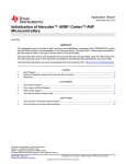
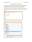
4.9
Fee Operation Flow
This section depicts a flow chart for a typical FEE operation.
Initialization
TI_ Fee_Init()
To be called only once at the
beginning to initialize the TI FEE
module.
TI FEE is in IDLE state after
successful initialization
Schedule a Data Operation
TI_FEE_WriteAsync()
TI_FEE_WriteSync()
TI_FEE_EraseBlock()
TI_FEE_InvalidateBlock() /
TI_FEE_Read()
Call any one of the data
operation functions as required.
A new operation can be initiated
only when the module is in “Idle”
state.
To be called at regular
intervals to complete the Data
operation.
TI_Fee_MainFu
nction()
Schedule Other
Application Tasks
TI_FeeInternal_Fee
Manager()
TI_Fee_getStatus()
No
Called by TI_FeeMain( ) whenever in
“Idle” state to handle internal
operations.
IDLE?
Yes
Returns the Job result of the last
operation.
TI_Fee_getJobResult()
Figure 6 Flow chart of a typical FEE operation
40
4.10 API Specification
This section constitutes the detailed reference for the entire API set
published to users of the TI FEE Driver.
4.10.1 TI FEE Driver Functions
4.10.1.1
Initilization Function (TI_Fee_Init)
This function provides functionality for initializing the TI FEE module. This
routine must be called only once at the beginning before commencing any
data operation.
Function Name:
Syntax:
Sync/Async:
Parameters
(in):
Return value:
Description:
TI_Fee_Init
void TI_Fee_Init (void)
Synchronous
None
None
Function to initialize the TI Fee module.
4.10.1.2 Async Write Function (TI_Fee_WriteAsync)
This function initiates an Asynchronous Write operation to a Data Block.
TI_Fee_MainFunction() function should be called at regular intervals to
finish the Async Write operation.
Function Name:
Syntax:
Sync/Async:
Parameters (in):
Return value:
Description:
TI_Fee_WriteAsync
Std_ReturnType TI_Fee_WriteAsync(
uint16 BlockNumber,
uint8* DataBufferPtr)
Asynchronous
Number of logical block,
also denoting start address
BlockNumber
of that block in Flash
memory.
DataBufferPtr
Pointer to data buffer.
E_OK: The write job was
accepted by the TI Fee
module
Std_ReturnType
E_NOT_OK: The write job
was not accepted by the TI
Fee module.
Function to initiate an Async Write job.
41
4.10.1.3 Sync Write Function (TI_Fee_WriteSync)
This function provides the functionality to program data to a Block
synchronously.
Function Name:
TI_Fee_WriteSync
Std_ReturnType TI_Fee_WriteSync(
uint16 BlockNumber,
uint8* DataBufferPtr)
Synchronous
Number of logical
block, also denoting
BlockNumber
start address of that
block in Flash
memory.
Pointer to data
DataBufferPtr
buffer.
E_OK: The write job
was accepted by the
TI Fee module
Std_ReturnType E_NOT_OK: The
write job was not
accepted by the TI
Fee module.
Function to program Data to a Block
synchronously.
Syntax:
Sync/Async:
Parameters (in):
Return value:
Description:
4.10.1.4 Read Function (TI_Fee_Read)
This function provides functionality for reading of data from a Block.
Function Name:
Syntax:
Sync/Async:
Parameters (in):
Return value:
Description:
TI_Fee_Read
Std_ReturnType TI_Fee_Read(
uint16 BlockNumber,
uint16 BlockOffset,
uint8* DataBufferPtr,
uint16 Length)
Synchronous
BlockNumber
Number of logical block, also
denoting start address of that
block in Flash memory.
BlockOffset
Read address offset inside the
block.
DataBufferPtr
Pointer to data buffer.
Length
Number of bytes to read.
E_OK: The Read job was
accepted by the TI Fee
module
Std_ReturnType
E_NOT_OK: The Read job
was not accepted by the TI
Fee module.
Function to read data from a Block.
42
4.10.1.5 Erase Function (TI_Fee_EraseImmediateBlock)
This function provides functionality for Erasing a Data Block asynchronously.
TI_Fee_MainFunction() function should be called at regular intervals to finish
the Erase operation.
Function Name:
Syntax:
Sync/Async:
Parameters (in):
Return value:
Description:
TI_Fee_EraseImmediateBlock
Std_ReturnType TI_Fee_EraseImmediateBlock(
uint16 BlockNumber)
Asynchronous
Number of logical block,
also denoting start address
BlockNumber
of that block in Flash
memory.
E_OK: The Erase job was
accepted by the TI Fee
module
Std_ReturnType
E_NOT_OK: The Erase job
was not accepted by the TI
Fee module.
Function to initiate Erase operation on a Data
Block
4.10.1.6 Invalidate Function (TI_Fee_InvalidateBlock)
This function provides functionality for invalidating a Data Block
asynchronously. TI_Fee_MainFunction() function should be called at
regular intervals to finish the Invalidate Block operation.
Function Name:
Syntax:
Sync/Async:
Parameters (in):
Return value:
Description:
TI_Fee_InvalidateBlock
Std_ReturnType TI_Fee_InvalidateBlock(
uint16 BlockNumber)
Asynchronous
Number of logical block, also
BlockNumber
denoting start address of
that block in Flash memory.
E_OK: The Invalidate Block
job was accepted by the TI
Fee module
Std_ReturnType
E_NOT_OK: The Invalidate
Block job was not accepted
by the TI Fee module.
Function to initiate an Invalidate operation on a
Data Block
43
4.10.1.7 Shutdown Function (TI_Fee_Shutdown)
This function provides functionality for performing a bulk data write when
shutting down the system synchronously. This function completes the
Async jobs which are in progress by performing a bulk Data Write while
shutting down the system synchronously.
Function Name:
Syntax:
Sync/Async:
Parameters (in):
Return value:
Description:
TI_Fee_Shutdown
Std_ReturnType TI_Fee_Shutdown()
Synchronous
None
E_OK: The Async job was
completed
Std_ReturnType
E_NOT_OK: The Async job
was not completed.
Function to perform bulk Data write prior to system
shutdown.
4.10.1.8 Get Version Info Function (TI_Fee_getVersionInfo)
This function returns the version information for the TI Fee module.
TI Fee specific version numbers MM.mm.rr
MM
mm
rr
– Major Version
– Minor Version
– Revision
Function Name:
Syntax:
Sync/Async:
Parameters (in):
T value:
Return
h
e
Description:
TI_Fee_getVersionInfo
void TI_Fee_getVersionInfo(
Std_VersionInfoType* VersionInfoPtr)
Synchronous
None
VersionInfoPtr
Pointer to standard version
information structure
Function to return the version information of the TI
Fee module.
44
4.10.1.9 Get Status Function (TI_Fee_GetStatus)
This function returns the status of the TI FEE module.
Function Name:
Syntax: T
h
Sync/Async:
e (in):
Parameters
f
u
n
c
Return value:
t
i
o
n
F
Description:
e
TI_Fee_GetStatus
TI_FeeStatusCodeType TI_Fee_GetStatus()
Synchronous
None
UNINIT: TI Fee Module has
not been initialized.
IDLE: TI Fee Module is
currently idle.
BUSY: TI Fee Module is
TI_FeeStatusCodeType
currently busy.
BUSY_INTERNAL: TI Fee
Module is currently busy
with internal management
operations
Function gets the status of the TI Fee module.
4.10.1.10 Get Job Result Function (TI_Fee_GetJobResult)
This function returns the result of the last job synchronously.
Function Name:
Syntax:
Sync/Async:
Parameters
(in):
Return value:
Description:
TI_Fee_GetJobResult
TI_FeeJobResultType TI_Fee_GetJobResult()
Synchronous
None
JOB_OK: The last job has
finished successfully.
JOB_PENDING: The last job
is waiting for execution or is
currently being executed.
JOB_CANCELLED: The last
job has been cancelled.
JOB_FAILED: The last job
failed.
TI_FeeJobResultType
BLOCK_INCONSISTENT:
The requested block is
inconsistent, it may contain
corrupted data.
BLOCK_INVALID: The
requested block has been
invalidated. The requested
read operation cannot be
performed.
Function gets the job result from the TI Fee module.
45
4.10.1.11 Task Function (TI_Fee_MainFunction)
This function handles the Write/Erase/Invalidate asynchronous jobs
initiated by TI_Fee_WriteAsync()/TI_Fee_EraseBlock()/TI_Fee_InvalidateBlock()
functions.
This function should be called at regular intervals by a scheduler.
This function internally calls another function “TI_FeeManager” whenever there is
no other job pending (“IDLE” State). “TI_FeeManager” function handles all the
background tasks/internal operations to manage the TI FEE module.
Note: The user has to schedule the tasks/data operations such that the TI FEE
module is in “IDLE” state for some time so that the internal operations are handled
correctly.
Function Name:
Syntax:
Sync/Async:
Parameters (in):
Return value:
Description:
TI_Fee_MainFunction
void TI_Fee_MainFunction(void)
Asynchronous
None
None
Function to handle the requested Async data
operations
4.10.1.12 Manager Function (TI_FeeManager)
The function TI_FeeManager() manages the Flash EEPROM Emulation and
is called when no other job is pending by the TI_FeeManager function. This
function handles all the background tasks to manage the FEE.
This routine is responsible for
Determine whether a Virtual Sector Copy operation is in progress. If so,
it should identify all the Valid Data Blocks in the old Virtual Sector and
copy them to the new Virtual Sector.
Determine if any of the Virtual Sector needs to be erased. If so, it
should erase that particular Virtual Sector.
This function is only called when the Fee module is in IDLE state. It
should set the Fee module to BUSY_INTERNAL state.
Function Name:
Syntax:
Sync/Async:
Parameters
(in):
TI_FeeInternal_FeeManager
TI_FeeStatusType TI_FeeManager(void)
Asynchronous
None
TI_FeeStatusType
Return value:
Description:
TI_FEE_OK: The job
was completed
TI_FEE_ERROR: The
job was not completed
due to an error.
Function to handle the requested Async data
operations
46
4.10.1.13 Format Function (TI_Fee_Format)
This function provides functionality for erasing all the Virtual Sectors
synchronously.
Function Name:
Syntax:
Sync/Async:
Parameters (in):
Return value:
Description:
TI_Fee_Format
void TI_Fee_Format(void)
Synchronous
None
None
Function formats all the Virtual Sectors.
Note: Calling this function will result in loss of data. This function should be
called only if you want to reconfigure the Data Blocks/Virtual Sectors or detect a
serious error condition.
4.10.1.14 TI_FeeErrorCode
This function provides functionality to identify occurrence of an error.
It returns ‘0’ if no error has occurred else it returns an Error code.
Function Name:
Syntax:
Sync/Async:
Reentrancy:
Parameters (in)
Parameters (out):
TI_FeeErrorCode( )
TI_FeeErrorCodeType TI_FeeErrorCode()
Synchronous
Non Reentrant
EEP Index
None
Return value:
TI_FeeErrorCodeType
Description:
Returns ‘0’ if no error has occurred else it returns an
Error code.
Returns an Error Code
4.10.1.15 TI_Fee_ErrorRecovery
This function provides functionality to recover from any severe errors.
47
Function Name:
Syntax:
Sync/Async:
Reentrancy:
TI_Fee_ErrorRecovery( )
void TI_Fee_ErrorRecovery()
Synchronous
Non Reentrant
Error_TwoActiveVS
Error_TwoCopyVS
Parameters (in)
Error Code
Error_SetupStateMachine
Error_NoActiveVS
Error_CopyButNoActiveVS
Error_NoFreeVS
Parameters (out):
Return value:
Description:
Virtual Sector Number
None
None
Function recovers from any severe errors.
4.11 Privilege Mode access
FEE needs following API’s to be executed in Privilege mode:
- TI_Fee_Init
- TI_FeeInternal_WriteDataF021
48