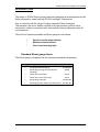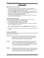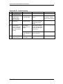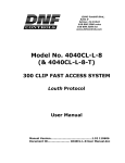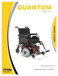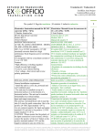
1
ST400 Series Boost Gauge USER MANUAL (541006-001) ST400 Series Tachometers User Manual Preface Congratulations Congratulations on choosing a Stack Boost gauge. This instrument will give you a wealth of track-side performance information to enable you to obtain the maximum from your vehicle. Registration Form Please complete and return the registration form contained in the package. This will allow us to keep you up to date on the latest developments from Stack. Purpose of this manual This manual will help you install your Boost gauge. It explains how to set up and configure the system for your vehicle. Related Products From Stack Limited If you need information about other Stack motor sport products, these can be obtained from Stack or from your local Stack dealer. Products available from Stack include: • Intelligent Tachometers • Speedometers • Lap Timing Systems • Analogue Sensors • Digital Sensors • Data Logging Systems • Display and Logging Systems • Display and Analysis Software STACK is a registered trademark of Stack Limited. Information in this publication is subject to change without notice and does not represent a commitment on the part of Stack Limited. No responsibility is accepted for error or omission. Copyright 1994, 1995, 1996 Stack Limited United Kingdom Telephone Numbers North America Telephone Numbers Sales: 01 869 240 404 Sales: (888) 867 5183 Tech. Support: 01 869 240 420 Tech. Support (888) 364 2511 Fax: 01 869 245 500 Fax: (888) 364 2609 Page 1 ST400 Series Tachometers User Manual CONTENTS PREFACE 1 INTRODUCTION 3 INSTALLATION 4 MECHANICAL INSTALLATION 4 ELECTRICAL INSTALLATION 4 INSTALLATION NOTES 4 TESTING 5 OPERATING THE BOOST GAUGE 5 GENERAL 5 STANDARD FUNCTIONS 6 GENERAL OPERATION 7 TECHNICAL SPECIFICATIONS Appendix A - Connection Details 8 9 Appendix B - Troubleshooting 10 Returned Goods Form 11 Page 2 ST400 Series Tachometers User Manual INTRODUCTION The range of STACK Boost gauges has been designed and developed from the highly successful, award winning STACK Intelligent Tachometer. Also in common with the range of highly respected Stack Intelligent Tachometers, the driver display consists of a high precision positive drive mechanism, which ensures accurate information is being displayed under all circumstances. The full list of features available on Boost gauges is as follows: * * * Positive needle boost display Maximum boost tell-tale Over boost warning light Standard Boost gauge Items The Boost gauge is supplied with the following standard components: Quantity Description Part No. 1 ST400 Series Boost gauge as supplied 1 Boost gauge Fixing Kit (Including the following) ST584 1 Switch Kit (2 switches) ST510 1 Panel mount over boost Light ST537 1 Boost gauge Harness 1 Boost gauge User Guide (This Document) 541006-001 ST594-204 Page 3 ST400 Series Tachometers User Manual INSTALLATION MECHANICAL INSTALLATION 1. The Boost gauge should be fitted in an 80mm (3.15in) diameter and secured using the fixing bracket supplied. It may be mounted in the hole at any angle of rotation for best viewing by the driver. 2. The 2 switches MUST be installed for the Boost gauge configuration and functions to be available. Take care in positioning these 2 switches as they need to be pressed simultaneously for some functions. Label the switches ‘M’ for Max and ‘R’ Reset. 3. The Over boost Light should be fitted in a position where it can easily be seen by the driver whilst driving. ELECTRICAL INSTALLATION The Boost gauge is supplied with a fully-wired harness to simplify wiring. 1. Fit the connector into the rear of the Boost gauge. 2. Fit the leads marked ‘M’ and ‘R’ to the two switches. 3. Fit the lead marked ‘SL’ to the Over boost Light. 4. The long red (B+) and black (B-) wires should be connected to the battery Positive and Negative respectively. Note: This Boost gauge is for use on NEGATIVE earth vehicles only. 5. The black 4 way (MSS) plug is for the boost sensor connection ST453 (not supplied). INSTALLATION NOTES The following Installation notes will help ensure good results if wiring the Boost gauge with your own harness: Connector The plastic connector has the pin numbers marked on the wire entry face. These may be used to ensure correct connection. If additional wires are required they should be insulated, multistranded cable of minimum current rating 5 Ampere Supply The supply to the Boost gauge should be within the range 8-16 volts DC - Positive connection to Pin 1 and negative to Pin 3. Pin 3 should be connected to the negative of the battery, either directly, or by connecting to existing wiring. Indirect connections to the vehicle chassis cannot be relied upon. Switches The switches supplied with the system are of a 'momentary action normally open' type and should be connected to the switch input on the 9 way connector and battery negative. Additional switch kits are available from Stack - request Part No. ST510. Page 4 ST400 Series Tachometers User Manual Outputs The output (pins 4) is an 'open-collector transistor' type. This is probably best thought of as an electronic switch connected on one side to battery negative. The load on the output should therefore be connected between battery positive and the relevant output. The maximum current which may be switched via either output is 0.2 Amperes and therefore they may be used to drive a lamp directly or larger loads and/or other equipment via a relay. TESTING Once the installation has been completed the Boost gauge may be powered up. When power is applied the needle should initially move to behind the Stack logo, when a slight buzz may be heard, and then be driven forward and stop at approx. 1 Bar (zero position with no ST453 connected). The green LED behind the STACK logo should be illuminated as a backlight. Start the engine and watch the Boost gauge. As the throttle setting is gradually increased the needle should rise in small steps and when the RPM is held steady should show a reasonably constant boost reading. If the Boost gauge is powered off with the engine still running, the needle will stay at whatever boost was being displayed when the power was removed. Further tests may only be carried out after reading the following chapter. OPERATING THE BOOST GAUGE GENERAL All functions of the Boost gauge are accessed via the two push-button switches attached via the 9 way connector. The main functions which are accessed in this way are as follows : * * * Tell-tale maximum display Reset tell-tale display Over boost indicator BOOST GAUGE FUNCTIONS Switch Functions All the functions of the Boost gauge are obtained by pressing either of the push button switches, labeled Max and Reset. These functions and the switches that obtain them are given in the following table: Page 5 ST400 Series Tachometers User Manual Functions available on Boost gauges Standard Function Max Boost Max Boost Max Reset Max Run/Stop Reset R Set Over boost R Increase Max Time Pressed Comments More than 0.5Sec Needle moves to maximum recorded boost 1 Sec 2 Sec Needle moves to current setting (0.05 Bar factory setting) As Required Move needle to required Over boost Decrease Exit Self Test R Max Max R R As Required 3 Sec Neither button pressed - needle reads actual Boost 5 Sec RED LED on. Needle moves around scale & then to zero. Key Press Sequence = Press Max RPM Switch Only R = Press Run/Stop Switch Only R = Press & hold Max Switch Then press Run switch Max Max Page 6 ST400 Series Tachometers User Manual General Operation Display Boost The Boost gauge will always show the current boost value of the engine, regardless of any other functions being performed simultaneously, unless the dial face is being used by that function. e.g. Show Max, Set Over boost. View Maximum boost The maximum value of boost measured will be continuously updated automatically and may be viewed by simply pressing the Max switch. The value displayed will be the highest value measured since the tell-tale memory was last reset. Reset Maximum boost The tell-tale may be reset at any time by using the Reset switch. This switch should be held pressed for approximately 1 second. Set Over boost There is an Over boost light output which may be adjusted using the dial and switches attached to the system. This Over boost limit controls the electrical output on pin 4 of the 9 pin connector. The output will switch 'ON' whenever the over boost setting is exceeded and can be used to switch a lamp to indicate overboost. To set the Over boost press and hold down the Reset switch for 2 seconds. The needle will then move to show the current setting. This setting may be adjusted at this time by using the two switches individually. The Max switch will increase the setting and the Reset switch will reduce it. When the Boost gauge detects that neither switch has been pressed for 3 seconds it will exit the Over boost setting mode. Self-test Functions The correct operation of the Boost gauge may be confirmed at any time using this feature. The tachometer is put into 'Self-Test' mode by first pressing and holding down the Max switch, pressing the Run switch and then continuing to hold down both switches for 5 seconds. The needle should then move around the scale and back to zero. Page 7 ST400 Series Tachometers User Manual Reset Boost gauge The Reset Boost gauge feature may be used to reset the memory of the Boost gauge at any time. The Boost gauge is reset by pressing the Reset switch while power is applied. TECHNICAL SPECIFICATIONS ALL MODELS - Unless otherwise specified Operating Temperature Storage Temperature Accuracy Humidity Vibration Supply Nett Weight Dimensions -20 deg C to +70 deg C -40 deg C to + 80 deg C Linear dials +/- 0.6% over temperature range Non linear dials +/- 0.45% over temperature range 0-95% Non-condensing 10-55Hz 5mm pk; 55Hz-1KHz 30g 12 hours 0.25 Amperes @ 8-16 Volts D.C. 400 grams 88mm (3.5in) diameter x 75mm (3.0in) deep Fixing details 80mm (3.15in) diameter cut-out Backlighting Over boost Limit Electrical Outputs Solid-state green LED User adjustable within the range of the dial face Pseudo open collector type (200 mA current sink maximum switched to battery negative) Page 8 ST400 Series Tachometers User Manual ST453 0-2.5 Bar Pressure Sensor Appendix A - Connection Details Page 9 ST400 Series Tachometers User Manual Appendix B - Troubleshooting No. Symptom Possible Cause Remedy Notes Gauge Operation 1 Display is dead or needle resetsvibrates or No green backlight Battery is dead or almost dead Recharge or replace battery 2 No reading Incorrect wiring. Check the connection of the boost sensor ST453 3 Boost gauge powers up OK but resets constantly when the engine is running Intermittent supply wiring to gauge. Check the 9w Pins & sockets for dirt. Check sockets for damage or if opened out Battery failing under vibration or load. Replace battery with known good unit Over boost limit set to high Set limit to required boost 4 Over boost Light doesn’t come on Page 10 Check if battery is connected. Check power lead continuity ST400 Series Tachometers User Manual Returned Goods Form In the unlikely event of a Stack part developing a fault and requiring repairs, you are kindly requested to send the part back to Stack or your dealer with a completed Returned Goods Form. Returning a part without this form will lengthen the repair time and possibly increase the cost of the repair. Company ________________________________________ Customer Address ________________________________________ (if different) ________________________________________ ________________________________________ _________________________ _________________________ Contact _________________________ ________________________________________ ________________________________________ Tel No. _________________________ Contact ________________________________________ Fax No. _________________________ Tel No. ________________________________________ Fax No. ________________________________________ Return Date _________________________ Details of part being returned Part No. ________________________________________________________________________________ Serial No. ________________________________________________________________________________ Description ________________________________________________________________________________ _ ________________________________________________________________________________ ________________________________________________________________________________ Other accessories included_______________________________________________________________________ (i.e. bracket, switches, etc.)_______________________________________________________________________ ________________________________________________________________________________ ________________________________________________________________________________ _ ________________________________________________________________________________ Details of Fault Please complete as fully as possible. This will speed the repair and return of the parts. Description of fault _______________________________________________________________________________ ______________________________________________________________________________________________ ______________________________________________________________________________________________ ______________________________________________________________________________________________ ______________________________________________________________________________________________ ______________________________________________________________________________________________ ______________________________________________________________________________________________ Details of vehicle ________________________________________________________________________________ ______________________________________________________________________________________________ ______________________________________________________________________________________________ ______________________________________________________________________________________________ ______________________________________________________________________________________________ Circumstances leading to fault ______________________________________________________________________ ______________________________________________________________________________________________ ______________________________________________________________________________________________ ______________________________________________________________________________________________ Stack use only Engineer _________________________________ Service No. ___________________ Date ___________________ Stack Ltd, Wedgwood Road, Bicester, Oxfordshire, OX26 4UL, England Tech, Support: +44 (0) 1869 240420 Sales: +44 (0) 1869 240404 Fax: +44 (0) 1869 245500 Stack Inc. 3545a Cove Creek Crt, Cumming, Georgia 30040, USA Tech.Support ++ (888) 364 2511 Sales: ++ (888) 867 5183 Fax: ++ (888) 364 2609 Page 11