1
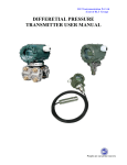
伟岸测器 WECAN PRECISION INSTRUMENTS SST Digital•Intelligent Pressure / Differential Pressure Transmitter User’s Manual CHONGQING WECAN PRECISION INSTRUMENTS CO., LTD Warning User’s Manual for SST Digital•Intelligent Pressure / Differential Pressure Transmitter 1. The transmitter is placed on the horizontal place before calibration. 2. Micro-range transmitter should be calibrated to zero after being mounted on-site. 3. The transmitter is required to mounted in the dry environment to avoid the rain. In a harsh environment, the outdoor mounting is required to use the protective housing. 4. The user is prohibited to dismantle the device. 5. The user is expected to check to see if the power supply of the transmitter is stable and clean (prevent the power supply from being AC disturbance). 6. For the products with the explosion-proof certificate, any of its elements or structure is not permitted to change. 7. The grounding bolts of the transmitter are required to connect with the earth . 8. The outfitted safe barrier of the intrinsically safety type transmitter must be used as per its users’ guide. 9. In the case of the intrinsically safety type transmitter being used in the explosion hazardous environment, the power transformer for the safe barrier must conform to the requirements of the Standard GB3836.4-2000, Division 8.1. 10.The special-purposed interconnection module of our company must be employed for the S-PORT communication interface. 11.The communication equipment and the software of our company must be employed for the transmitter marking and temperature compensation with HART communications. The user is expected to read this manual carefully after opening the box! Catalogue User’s Manual for SST Digital•Intelligent Pressure / Differential Pressure Transmitter Introduction......................................................................................... 5 1. Overview........................................................................................ 7 1.1 SST Series Digital•Intelligent Pressure/ Differential Pressure Transmitter................................................................................................... 7 1.1.1 Integral Appearance.................................................................. 7 1.1.2 Integral Structure....................................................................... 8 1.1.3 Introduction to Working Principle............................................... 9 1.2 SST Digital•Intelligent Direct-Coupled Pressure / Level Transmitter 10 1.2.1 Integral Appearance and Structure............................................ 10 1.2.2 Introduction to Working Principle............................................... 12 2. Mounting For Use........................................................................... 13 2.1 SST Digital Series•Intelligent Pressure/Differential Pressure Transmitter................................................................................................... 13 2.1.1 Integral Appearance Dimensional Drawing............................... 13 2.1.2 On-site Mounting....................................................................... 14 2.2 SST Series Digital•Intelligent direct-coupled Pressure/ Level Transmitter................................................................................................... 19 2.2.1 Integral Appearance.................................................................. 19 2.2.2. On-site Mounting...................................................................... 21 2.3 Issues Relating to Measurement Ways........................................ 22 2.4 Electrical Mounting....................................................................... 25 2.5 intrinsically Safety Type Explosion-Proof Transmitter System Wiring Drawing.............................................................................................. 27 3. Debugging and Operation.............................................................. 28 3.1 Summary...................................................................................... 28 3.1.1 Keys Definition.......................................................................... 29 3.1.2 Description of Keys Functions................................................... 30 3.1.3 Working State Display............................................................... 30 3.1.4 Menu Description...................................................................... 30 3.1.5 Input Symbols............................................................................ 31 3.1.6 Input Integer.............................................................................. 31 3.1.7 Input Decimal............................................................................ 31 3.2 Accuracy Micro-tuning of Transmitter........................................... 32 User’s Manual for SST Digital•Intelligent Pressure / Differential Pressure Transmitter 3.3 Instruction of Main Menu.............................................................. 33 3.4 Detailed Instruction of Sub-menu Operation................................ 34 4. User’s Maintenance........................................................................ 41 4.1 Summary...................................................................................... 41 4.2 Soft Maintenance......................................................................... 41 4.3 Hard Maintenance........................................................................ 42 4.4 Troubleshooting............................................................................ 43 5. Instructions For Mounting and Use of Flange-Type Transmitter.... 46 5.1 Summary...................................................................................... 46 5.2 Specifications:.............................................................................. 46 5.3 Calibration of Instrument.............................................................. 50 5.4 Usage of Instrument..................................................................... 50 5.5 Instrument Maintenance............................................................... 57 5.6 Instructions for Order.................................................................... 57 Appendix............................................................................................ 60 A.1 Model Composition...................................................................... 60 A.2 Accessories and Material Code................................................... 61 A.3 Functional Indices........................................................................ 62 A.4 Accessories.................................................................................. 68 A.5 Precautions.................................................................................. 68 Introduction User’s Manual for SST Digital•Intelligent Pressure / Differential Pressure Transmitter SST Series Digital•Intelligent Pressure/Differential Pressure Transmitter is a multipurpose digitalized intelligent instrument developed by ChongQing WECAN Precision Instruments Co., Ltd., including capacitance pressure /differential pressure transmitter and direct-coupled pressure/ level transmitter. It is made on the basis of the mature and dependable sensing technology, combining the advanced single-chip computer technology and sensor digital convert technology. 16-bit single chip is adopted as its core element, with its powerful function and high-speed calculation capacity ensuring the excellent quality of the transmitter. The whole design frame focuses on its dependability, stability and high precision and intelligentization, meeting the growing demand in on-site industrial use. To get this goal, digitalized signal processing technology is used in the software to ensure its disturbance capacity and zero point stability. Meanwhile, it has the Zero Stability Capacity (ZSC) and Temperature Supplementing Capacity (TSC). The powerful interface functions guarantees an excellent interactivity with no need of manual operator. Its digitalized meter head can display 3 physical parameters including pressure, temperature and current, and 0-100% analogue indications. Keystroke operation can finish the basic settings of zero shift, range setting, damping setting under the circumstance of no standard pressure, greatly convenient for the onsite debugging. S-PORT serial communication port can communicate with the computer through the special purposed interconnection module, while the upper computer interface can finish more functions than the keystroke operation. By connecting with module RS485, it can realize the remote transmission of digital signal, or the building up of RS485 industrial LAN. SST series digitalized Intelligent Pressure/ Differential Pressure User’s Manual for SST Digital•Intelligent Pressure / Differential Pressure Transmitter Transmitter has the optional HART module. After the transmitter is added the HART module, it has HART communication capacity, with the conventional operation being controlled with the general manual operator. The special communication equipment and software provided by our company can operate the marking and temperature supplementation actions. SST series digitalized Intelligent Pressure/ Differential Pressure Transmitter can be widely used in the sectors such as petroleum, chemical, iron & steel, power generator, light industry and environmental protection, capable of realizing the measurement of various pressures, differential pressures, flows and level, adaptable for all kinds of harsh and hazardous environment and corrosive mediums. 1. Overview User’s Manual for SST Digital•Intelligent Pressure / Differential Pressure Transmitter 1.1 SST Series Digital•Intelligent Pressure/ Differential Pressure Transmitter 1.1.1 Integral Appearance Length/width/height/quality (no accessories): 98 mm/78mm/169mm/ 2.4kg Fig. 1-1 User’s Manual for SST Digital•Intelligent Pressure / Differential Pressure Transmitter 1.1.2 Integral Structure Fig. 1-2 User’s Manual for SST Digital•Intelligent Pressure / Differential Pressure Transmitter 1.1.3 Introduction to Working Principle Temperature sensor Signal change circuit Pressure Pressure 16-bit single chip computer Current control circuit 4-20mA signal output Communication port Linear constant Measurement scope constant Transmitter configuration Button Zero alignment button Display module Fig. 1-3 As indicated in the working principle diagram Fig. 1-3, the outside pressure or differential pressure will cause some change in the sensor capacitance value. Through the digital signal conversion, it will change into the frequency signal, which is sent to the microprocessor. After the calculation by microprocessor, a current control signal will be output to the current control circuit, converted into analogue 4-20mA current output. Meanwhile, the microprocessor is responsible for the interactive and other actions (display and setting). The communication port used for digital communication needs the special port of our company. HART module will realize the transmitter HART communication. User’s Manual for SST Digital•Intelligent Pressure / Differential Pressure Transmitter 1.2 SST Digital•Intelligent Direct-Coupled Pressure / Level Transmitter 1.2.1 Integral Appearance and Structure 1) SST2001 Integral Appearance Length/width/height/quality (no accessories): 98 mm/78mm/152mm/ 0.75kg Fig. 1-4 10 User’s Manual for SST Digital•Intelligent Pressure / Differential Pressure Transmitter 2) SST2138 Integral Appearance Length/width/height/quality (no accessories): 98 mm/78mm/ 131+(wire length) mm /0.75kg (varied in weight for different types) Fig. 1-5 11 User’s Manual for SST Digital•Intelligent Pressure / Differential Pressure Transmitter 1.2.2 Introduction to Working Principle Temperature Sensor 16-bit single chip computer A/D Conversion Linear constant Measurement scope constant Transmitter Configuration Current Control Circuit 4-20mA Signal output Communication port button Display module Zero alignment button Fig. 1-6 As indicated in the working principle diagram Fig. 1-3, the outside pressure or differential pressure will cause some changes in the sensor resistance value and the output value of bridge voltage. Through A/D conversion, it will change into the digital signal which is sent to the microprocessor for calculation; then a current control signal will be output to the current control circuit, converted into analogue 4-20mA current output. Meanwhile, the microprocessor is responsible for the interactive and other actions (display and setting). The communication port used for digital communication needs the special port of our company. HART module will realize the transmitter HART communication. 12 2. Mounting For Use User’s Manual for SST Digital•Intelligent Pressure / Differential Pressure Transmitter 2.1 SST Series Digital•Intelligent Pressure/Differential Pressure Transmitter 2.1.1 Integral Appearance Dimensional Drawing 17 mm is the minimum backward distance of the wiring box cover. Fig. 2-1 M Model Size(mm) 1200 1300 1400 1500 1600 1700 1800 1900 1000 54 55.6 13 57.2 58.4 59.2 User’s Manual for SST Digital•Intelligent Pressure / Differential Pressure Transmitter 2.1.2 On-site Mounting 1) Mounting Steps The transmitter can be directly mounted onto the 2-inch conduit or onto the wall and the meter panel. (See Fig. 2-2.) B1 conduit curve bracket B2 plate curve bracket B3 conduit flat bracket Fig. 2-2 After releasing the bolt, electronics housing can be rotated 90°to the left and right. Warning: Never exceed 90°to avoid the inside parallel wires breaking! e 2) Way of Pressure Impulse There are 3 kinds of ways of pressure impulse: 14 User’s Manual for SST Digital•Intelligent Pressure / Differential Pressure Transmitter Joint Flange Way (Ordering Code G1) Fig.2-4 Weld Conduit Connector (Ordering Code G2) Fig. 2-5 Integral 3-valve group (Ordering Code G3) Fig. 2-6 Notes: Pressure transmitter uses one terminal only(H or L), with another terminal for reference . 15 User’s Manual for SST Digital•Intelligent Pressure / Differential Pressure Transmitter 3) Vent/drain valve Usually, vent/drain valve should all be locked up, and only put in use in need of discharge gas/fluid; our company has the default config.uration standard of up/down vent/drain valve. Vent Valve (up) Drain Valve (down) Fig. 2-7 4) Cover Lock Screw down the bolt to open up the cover; release the bolt to lock up the cover. Usually, the cover should be ensured of being screwing down to avoid its inside being damaged. Fig. 2-8 5) Process Connection Orifice Distance Adjustment The process connection orifice on the pressure capacity room is NPT1/4-18. It is required to seal these orifices. In the use of the joint flange connector, dismantling the upper and lower bolts of the connector can easily disassembly the transmitter from the production unit. The center distance between 2 process connection orifices is 54mm. the 16 User’s Manual for SST Digital•Intelligent Pressure / Differential Pressure Transmitter center distance can vary in the range of 50.8mm, 54mm and 57.2 mm by rotating the joint flange connector as indicated as the following Figure: 6) Fig.2-9 Mounting and Calibration Due to the gravity of the diaphragm and silicone oil, the transmitter gravity to be mounted in horizontal plane will result in zero deviation (about 240Pa in the maximum amount), and particularly serious for the transmitters with middle & low range. Yet it can be calibrated to zero on the site. In operation, there is a calibration button on the left side of the housing body of the transmitter. Open the nameplate and keep pressing it down for about 5 sec to finish the zero alignment. See Fig. (2-10): Zero alignment Special Note: Please make sure that the transmitter has a zero value of differential pressure in zero alignment. Or the transmitter will induct the zero shift!!! Fig. 2-10 17 User’s Manual for SST Digital•Intelligent Pressure / Differential Pressure Transmitter 7) Attention to Mounting Operation 1. keep the transmitter away from the tested mediums such as corrosive or high temperature (≥ 90℃ ) . 2. Prevent the sediment from being left in the conduit. 3. Make the pressure conduit as short as possible. 4. The fluid pressure head in both conduits should be kept in balance. 5. The pressure conduit should be mounted where temperature grade and small fluctuation area . 6. Prevent the inside pressure conduit from being crystallized or iced at low temperature. 18 User’s Manual for SST Digital•Intelligent Pressure / Differential Pressure Transmitter 2.2 SST Series Digital•Intelligent direct-coupled Pressure/ Level Transmitter 2.2.1 Integral Appearance SST 2001 Structure Dimensional Drawing Process Port Screw (M20×1.5 as default ) Fig. 2-11 19 User’s Manual for SST Digital•Intelligent Pressure / Differential Pressure Transmitter SST 2318 Structure Dimensional Drawing Electronic Box Flange (optional) Stainless Steel Pipe Pipe Armored Metal Sleeve Armored Fluid Sensor Head Fig. 2-12 20 User’s Manual for SST Digital•Intelligent Pressure / Differential Pressure Transmitter 2.2.2. On-site Mounting SST 2001 Series direct-coupled Pressure Transmitter can be directly mounted onto the conduits by use of M20×1.5 or NPT1/2 outer screw, with the screwing moment no more than 30ft-1bs (or 40N.m); SST 2318 Series direct-coupled Pressure Transmitter can be put into the fluid for use, optional in 3 mounting ways including local, bracket and flange. Try to mount the transmitter in a place with small temperature difference, and avoid vibration and concussion. When mounting in an open air, try to keep the transmitter in a dry and ventilated place, avoid the strong sunshine and raining, which may result in the decline in the integral performance and longevity. In the process of mounting a transmitter, the following cases are required to take into consideration: ■ Prevent the cable from getting direct contact with the strong corrosive mediums ■ Avoid the sediment or jam of residues inside the probe and pressure impulse conduit ■ Pressure impulse conduit should be as short as possible ■ The transmitter or pressure impulse conduit should be mounted a place with small temperature difference. In wiring of the transmitter the signal wire should not go through with other power wires the wiring pipe or groove, nor through the nearly position of the equipment with bigger power. The measurement of steam or other high temperature mediums can be done through the process by cooling device. The measurement of steam agent may be done by way of getting the pressure impulse conduit filled with water or other fluids to avoid the direct contact of the transmitter with steam. 21 User’s Manual for SST Digital•Intelligent Pressure / Differential Pressure Transmitter 2.3 Issues Relating to Measurement Ways Fluid Measurement: In the measurement of fluid flow, the pressure taps should be breached on the side of the process conduit to avoid the sediment of dregs. Meanwhile, the transmitter should be mounted beside or under the pressure taps, to prevent the air bubbles from being discharged into the process conduit. Gas Measurement: In the measurement of gas flow, the pressure taps should be opened breached at the top or side of the process conduit. And the transmitter should be mounted beside or on the process conduit, to make the collected fluid flow easily into the process conduit. Steam Measurement: In the measurement of steam flow, the pressure taps should be opened breached on the side of the process conduit. And the transmitter should be mounted under the process conduit, to make the cooled collected fluid flow into the process conduit. To be noted, in the measurement of steam or other high temperature mediums, its temperature should not exceed the limited level for the use of transmitter. As for the measured agent like steam, the conduit is required to be filled with water to prevent the steam from being direct contact with the transmitter. Thus when the transmitter is in working state, its capacitance variation would be ignored with no need of mounting cooling pot. Level Measurement: The differential pressure transmitter used for measuring the fluid level is to detect static pressure head for the measurement of fluid bar. This pressure depends on the fluid level and the fluid proportion, with its value equal to the fluid height of the upper part of the pressure taps multiplying the fluid proportion, and irrelevant to the container’s volume or form. Fluid Level Measurement of Breached Container In this kind measurement, the transmitter is mounted at the bottom near the container so as to measure the corresponding pressure of the upper part of fluid level. The pressure of the container fluid level acts on the high-pressure 22 User’s Manual for SST Digital•Intelligent Pressure / Differential Pressure Transmitter side of the transmitter, while its low-pressure side open to the atmosphere. If the lowest value in the range of the tested fluid level is at the upper position of the transmitter mounting location, the transmitter must undergo the positive shift. Fluid Level Measurement of Sealed Container In the sealed container, the pressure P0 of the upper fluid container affects the tested pressure of the container bottom. So the pressure of the container bottom is equal to that the fluid level height multiplies the fluid proportion then plus the pressure P0 of the sealed container. To test the real value of fluid level, it is right to minus the pressure P0 of the container from the tested pressure of the container bottom. For this, a pressure taps should be breached at the container top, and have it connected to the low-pressure side of transmitter. Thus, the pressure inside the container will act on both high and low sides of the transmitter. The result obtained is a direct proportion to the product of the fluid level height multiplying with fluid proportion. Pressure Impulse Connection Ways 1) Dry Pressure Impulse Connection In the case of the gas on the fluid refused to condensate, the connection conduit at the low side of transmitter will keep dry. This is so called Dry pressure impulse connection. The way determining the measure range of transmitter is the same to that of breached container fluid level. 2) Wet pressure impulse Connection In the case of the gas on the fluid getting condensate, there will be a gradual fluid accumulation inside the pressure conduit at the low-pressure side of transmitter, leading to an error on measurement. To avoid this error, certain fluid is filled into the low-pressure side of transmitter beforehand; this is called Wet pressure impulse Connection. The above situation will make the transmitter be with a head at the low-pressure side, so a negative shift is needed. 23 User’s Manual for SST Digital•Intelligent Pressure / Differential Pressure Transmitter Decrease Error Pressure conduit makes transmitter connect with process technic conduit, and transfer the pressure at the pressure taps along the technic conduit to the transmitter. In the process of pressure transmission, the following reasons may cause the errors: 1) Leakiness; 2) Abrasion loss (particularly in the use of detergent); 3) Some gas existing in the fluid conduit (resulting in pressure head error); 4) Accumulated fluid in the gas conduit (resulting in pressure head error); 5) Density difference caused by the time difference between conduits (resulting in pressure head error); The following ways can be used to decrease the errors: 1) Pressure conduit should be as short as possible; 2) When measuring fluid or steam, the pressure conduit should be connected up to the process technic conduit, with its rake less than 1/12; 3) For the measurement of gas, the pressure conduit should be connected down to the process technic conduit, with its rake not less than 1/12; 4) The layout of fluid pressure conduit should avoid an extruded point in the middle part, while the gas pressure conduit avoids the sunken part; 5) Both pressure conduit should keep in the same temperature; 6) To avoid the friction, the diameter of pressure conduit should be wide enough; 7) No gas is found in the pressure conduit filled with fluid; 8) When using isolating fluid, the fluids in both pressure conduits should be the same; 9) When using detergents, the connection part of detergent should be near to the pressure taps of technic pipe; the conduit way passed through by the detergent should be the same in length and diameter. Try to avoid detergent passing through the transmitter. 24 User’s Manual for SST Digital•Intelligent Pressure / Differential Pressure Transmitter 2.4 Electrical Mounting System Wiring Drawing: Ampere meter Power Supply Standard 24V DC Supply Fig.2-13 (Note 1: User can install the distributor or safe barriers per the onsite and design requirements. For details, see the usage of distributor and safe barrier.) It is recommended to choose the explosion-proof impulse terminal with the cable diameter of φ8 – φ12. The connection terminal is set with test terminal, convenient for the online test of the operator. Signal terminal is situated in a separate housing of the electrical box. Screw up the meter cover for wiring. The upper end is for signal, while the lower end is for test meter. Fig. 2-13 indicated the terminal location. The test terminal is used for connecting any optional indicator head or test. The power supply goes to the transmitter through the si nal line, with no need of additional wiring. ! Special Attention: Do not connect the power signal line to the test terminal; otherwise the diode inside the test terminal would be destroyed. 25 User’s Manual for SST Digital•Intelligent Pressure / Differential Pressure Transmitter In case of the diode being damaged unfortunately, shortcutting the test terminal can keep the transmitter working on, except the indicator unable to connect. No need to shield the signal wire, and litz wire can be used for better effect. Do not lay together the signal wire and other power wires, to get near to the heacy current installation. The wiring orifice on the housing body of transmitter should be sealed or inserted in a plug smeared with seal glue to prevent the humidity being accumulated in the housing. In the case of the wiring not being sealed, the transmitter should be mounted with the wiring orifice upside down to discharge the moisture. The signal line may ignore the grounding (hanging) or get to ground at any point on the loop line. The transmitter housing can have grounding or not, and the power has no need of being stabilized, even if the power ripples has a peak-to-peak value of 1V. And the output ripples of transmitter can also be ignored. Since the transmitter gets grounded by way of capacitance coupling, it is not appropriate to use a high-voltage mega-ohm meter to check the insulation resistance. The voltage used for checking the line should be no more than 100 V. The transmitter circuitry is designed as intrinsic safe circuitry, limiting the output current below 30 mA DC (35 mA DC under the condition of high temperature or high voltage). 26 User’s Manual for SST Digital•Intelligent Pressure / Differential Pressure Transmitter 2.5 intrinsically Safety Type Explosion-Proof Transmitter System Wiring Drawing Ui: Ii: Pi: 28v DC 30mA 0.84W Intrinsically safety type Terminal Non-intrinsically safety type Terminal Connect to Secondary Meter Safe Zone Safe barrier Transmitter Dangerous Zone Um≥250V AC/DC Uo≤28V DC Io≤30mA Po≤0.84W Note: See GB3836, 4-2000 standard for the definitions of Um, Uo, Io, Po, Ui, Ii, Pi . The connection wire or cable between safe barrier and transmitter has a largest allowed distribution capacitance CP of no more than 0.02uF, and the largest allowed distribution inductance LP of not more than 2.0mH. 27 3. Debugging and Operation User’s Manual for SST Digital•Intelligent Pressure / Differential Pressure Transmitter 3.1 Summary Meter Head Panel Diagram (All Liquid Crystal Display) Fig. 3-1 28 User’s Manual for SST Digital•Intelligent Pressure / Differential Pressure Transmitter Instruction to Display: PV-----Transmitter in measurement state SV-----Transmitter in setting state Er-----Excessive pressure or sensor circuit fault mA-----Signifies LCD display of output current value %-----Signifies LCD display of percentage of measurement pressure corresponding to setting range ℃ -----Signifies the average value of measurement agent and environment temperature √-----Signifies the output current of transmitter in square root state kPa-----Signifies LCD display of pressure unit MPa---- Signifies LCD display of pressure unit 0 50 100% --------Signifies the analogue indication of pressure measurement corresponding to setting range S-PORT---Special Communications Port 3.1.1 Keys Definition 29 User’s Manual for SST Digital•Intelligent Pressure / Differential Pressure Transmitter 3.1.2 Description of Keys Functions ESC : cancel the current operation and return to the previous operation MOVE: move cursor and decimal point in typing data ENTER: enter a menu and confirm a operation DOWN: As paging down a menu and inputting data, cursor position digital less 1 Up: As paging up a menu and inputting data, cursor position digital plus 1 3.1.3 Working State Display PV Display: in measurement state SV Display: in setting state Er Display: signal circuit failure or pressure exceeded 3.1.4 Menu Description Menu is constructed in levels, and the maximum is 4 levels, as follows: Measurement state sub-menu Main Menu parameters setting/marking Rolling and Selection of Menu: Press the UP key roll to display the items in ascending order Press the DOWN key , roll to display the items in descending order Press the ENTER key , enter the corresponding sub-menu or specific function operations Press the ESC key , return to the previous menu As indicated below, 30 User’s Manual for SST Digital•Intelligent Pressure / Differential Pressure Transmitter 3.1.5 Input Symbols Use UP or DOWN to change the highest digital (the left-most one of the 6-digital LED), and its loop order is 0…9, -0, …; the common digitals have the loop order as: 0…9, 0… 3.1.6 Input Integer When an integer is input, the screen displays XXXXXX, and the lowest digital flashes to indicate the cursor position. Press the UP key to increase 1 number of the cursor location Press the DOWN key to decrease 1 number of the cursor location When a negative number is input, the negative symbol is input at the location of the highest digital Press the MOVE key to move 1 digital to the left in cursor loop Press the ESC key to return without saving Press the ENTER key to save and return 3.1.7 Input Decimal When a decimal is input, the screen displays XXX.XX (depending on the decimal digital), and the decimal digital flashes to indicate the cursor position. Press the UP key once and release to increase 1 number of the cursor location Press the DOWN key once and release to decrease 1 number of the cursor location When a negative number is input, the negative symbol is input at the location of the highest digital Press the MOVE key to loop the cursor by 1 digital to the left, and decimal will follow the move Press the ESC key to return without a save Press the ENTER key to save and return Use UP and DOWN to change the highest digital number and input the negative symbol 31 User’s Manual for SST Digital•Intelligent Pressure / Differential Pressure Transmitter 3.2 Accuracy Fine tuning of Transmitter (Instruction: since the differences of the standard and gravity acceleration may result in accuracy error of transmitter. Users can do the output micro tuning through this operation to enhance its accuracy.) 1) Reset: press down the UP and DOWN keys at the same time for about 5 sec will reset the transmitter, and the program restarts. 2) Enter Menu: Press down ENTER for about 5 sec to enter Main Menu for the corresponding operations. 3) Calibration Operation: i) Instruction: A transmitter has 3 values of calibration: Zero Point, shift Zero Point and Range Point. Zero Point: difference value is zero, e.g. H and L rooms have the same pressure, defined as the physical zero points. Shift Zero Point: 4mA pressure point (the possible physical zero point), defined as logic zero point. Range Point: 20mA pressure point (the possible physical zero point). ii) Operation A) Under the condition of no standard pressure, only the physical zero point can be calibrated. Method: Press down the housing body button for zero alignment or the DOWN key for about 5 sec, then “GOOD” will display after releasing it, prompting the completion of physical zero point calibration, “0” will display after calibration. B) Under the condition of standard pressure source, it is available for the calibration of transfer range point and zero point. But these operations cannot be done usually. A password is a must to acquire the authority before doing these operations. ① When the authority is acquired and the shift zero point is not “0”, the shift zero point can be calibrated. Method: after the pressure is added up to the stabilized pressure value of transfer zero point, press down the DOWN key and the MOVE key for about 5 sec for a short moment display of “00”, the calibration of shift zero point will be completed. 32 User’s Manual for SST Digital•Intelligent Pressure / Differential Pressure Transmitter ② When the authority is acquired and only the range point is not “0”, the range point can be calibrated. Method: after the pressure is added up to the stabilized pressure value of range point, press down the key UP for about 5 sec, then “GOOD” will display for seconds after releasing it, prompting the completion of range point calibration. 3.3 Instruction of Main Menu Usually, the main menu has 7 items for rolling display, respectively as follows: Sub 0 : display setting (unit setting) Sub 1 : zero shift Sub 2 : range setting Sub 3 : pressure port H.L terminals switching Sub 4 : setting communications address Sub 5 : damping setting Sub 6 : password verifying and setting (after verification is successful) After the password is input and verified, the menus will change to a rolling display of 14 items. A restart will go back to the 7-item menu. The first 6 items in the 14-item menus are the same to the above mentioned, and the rest items are respectively as follows: Sub 7 : current parameters setting (R0, R100) Sub 8 : P100 setting (maximum rating range) Sub 9 : display or input differential pressure marking point Sub 10 : mark differential pressures in room temperature Sub 11 : reverse mark differential pressures in room temperature Sub 12 : display or input temperature point Sub 13 : display or input temperature compensation point In the state of main menu, no key operation for 2 min will return to the measurement state. 33 User’s Manual for SST Digital•Intelligent Pressure / Differential Pressure Transmitter 3.4 Detailed Instruction of Sub-menu Operation I. Sub 0 display unit setting After entering Sub 0 menu, the display will be the current measurement value and the corresponding unit; when the current is output in square root, it will display “√” unit optional menu, 6 items in rolling display are as follows in sequence: 0 kPa 1 MPa 2 mA 3 % 4 √mA 5 ℃ Press the UP key and the above items will roll to display in ascending order Press the DOWN key and the above items will roll to display in descending order Press the ENTER key will complete selection, and save into memorizer, then return to main menu Press the ESC key will cancel the operation and the unit remains unchanged, then return to main menu. In the state of this menu with no key action for 2 min, the menu will return to the measurement state with the unit remaining unchanged. Note: output way of current depends only on item 2 and 4, and the other options will not change the original current output way. No square root function is configured with the digital•intelligent direct-coupled pressure/level transmitter. 34 User’s Manual for SST Digital•Intelligent Pressure / Differential Pressure Transmitter II. Sub 1 Zero Shift Upon entering Sub 1 menus the display will prompt the input of a floating-point number. The display is the original setting. Input the zero transfer point (unit kPa), press ENTER and then return to main menu after this operation. The setting of zero point transfer will have no impact on the range, but the setting is not allowed to exceed the maximum rating range. III. Sub 2 Range Setting Same to the operation of Sub 1 menu, Sub 2 is only used for setting the full-range, which is not allowed to exceed the maximum rating range as well. IV. Sub 3 Switching Between High-Pressure Terminal and LowPressure Terminal Notes: this function is not available for SST Series Digital•Intelligent direct-coupled Pressure/Level Transmitter. Usually, differential pressure transmitter is definite with the H-L ,set upon leaving the factory, and the user is not permitted to change it. After entering this menu, it will display the current setting status and a change is not permitted. To reset it, input the password in Sub 6 first to get the calibration authority, then use UP and DOWN keys to set the options, and ENTER to confirm. ESC will keep the original setting and return. V. Sub 4 Setting of Communications Address As more than one instruments are connected and communicate with the upper computer, each instrument must have different address. Otherwise, a response confliction may occur, failing to finish communica- 35 User’s Manual for SST Digital•Intelligent Pressure / Differential Pressure Transmitter tions task. Upon entering this menu, an integral will display, the original address point. Input the new address and press ENTER to finish the setting, and return to the main menu. Press ESC will keep the original setting and return to main menu. VI. Sub 5 Damping Setting Same to the operation of Sub 4, Sub 5 is only used for setting damping value (0-32 sec or more). VII. Sub 6 Password Management Upon entering Sub 6 menu, input an integral, the password, at the screen prompt, the program will verify whether or not the password is correct. If the input password is wrong, it will display “ERROR”, press ENTER will return to main menu. If the input password is the access password or user password, the menu system will be extended into 14-item menu, allowing more operations. Meanwhile, at this moment, Sub 6 will reset the user’s password. If a special password is input, and the corresponding function can be finished as described below: 040820: cancel shift zero alignment and obtain calibration authority. 040821: cancel range calibration and obtain calibration authority. 050728: clear physical calibration Note: the operations in Sub 7 through Sub 13 are relating to the core parameters, and forbidden to use without the authority. This manual has no instruction on these operations. 36 User’s Manual for SST Digital•Intelligent Pressure / Differential Pressure Transmitter Examples For The Operations: 1) Zero point set as –5kPa (negative input) Press down the ENTER key for about 5 sec, and release it to enter main menu. The display is as follows: Press UP to roll the menu and repeat it once, the display is as follows: Press ENTER to enter sub-menu and the display is as follows: The current value is 0 The cursor flashes before the decimal point Press the MOVE key to move the cursor and decimal point and repeat it for 3 times, the display is as follows: 37 User’s Manual for SST Digital•Intelligent Pressure / Differential Pressure Transmitter Press the UP key to regulate number and repeat it for 5 times, the display is as follows: Press the MOVE key to move the cursor and decimal point and repeat it for once, the display is as follows: Press the DOWN key to input the negative symbol and repeat it for once, the display is as follows: Press the MOVE key to move the cursor and decimal point and repeat it for 5 times, the display is as follows: Press ENTER to save the setting and return to main menu Press ESC to return to measurement state. 38 User’s Manual for SST Digital•Intelligent Pressure / Differential Pressure Transmitter 2) Range set as 7.2 kPa (decimal input) Press down ENTER for about 5 sec, and release it to enter main menu, the display is as follows: Press UP to roll the menu and repeat it for twice, the display is as follows: Press ENTER to enter Sub 2 sub-menu, and the display is as follows: Display the previous value (8kPa), the cursor flashes at the units’ digit Press DOWN once, less the cursor digits, the display is as follows: 39 User’s Manual for SST Digital•Intelligent Pressure / Differential Pressure Transmitter Press MOVE to move the cursor to the 2nd digit in the right as follows: Press UP to increase the cursor digits for a consecutive 2 times in the following display: Press MOVE to move the cursor to the 3rd digit in the right as follows: Press ENTER to save the setting and return to main-menu Press ESC to enter the measurement state. 40 4. User’s Maintenance User’s Manual for SST Digital•Intelligent Pressure / Differential Pressure Transmitter 4.1 Summary Our digital•intelligent pressure/ differential pressure transmitter is smart and fixed, with Zero Stability Capacity (ZSC) and Temperature Supplementing Capacity (TSC) plus seldom-regular maintenance. Functionally, a digital transmitter is largely comprised of 3 parts including sensor modules, main circuit board and meter head. Where: main circuit board is fastened with sensor modules with bolts, and coagulated with sol as a whole. This integrated design structure can stabilize the distributed capacitance and parasitic capacitance between them. Meanwhile, the decreasing of signal collecting circuit and signal source distance reduces the disturbance. This compact structure also provide a more solid and reliable transmitter with few problems occurred. 4.2 Soft Maintenance The digital transmitter is an intelligentized product with its parameters open to the users, who may adjust as per the actual situation the zero point, and set range and damping, even re-mark it. Likewise, this could cause the confused parameter setting or core parameter being modified resulting in a soft fault. In the case of core parameters (marked value upon ex-factory) being changed, it is necessary to re-mark it as per the operational instruction or reset the parameters through the way of communications, so as to make it work normally. In the actual need of zero point re-calibration, press down the button for zero alignment on the side of the transmitter for about 5 sec to realize the manual operation. In need of the setting of other parameters, just screw up the meter head cover, and finish the operation with the keystrokes or communications. 41 User’s Manual for SST Digital•Intelligent Pressure / Differential Pressure Transmitter 4.3 Hard Maintenance Generally, sensor modules, circuit board and meter head are not in the range of on-site repair. The hard fault maintenance item is only limited to circuit connection check, transmitter cleaning, changing meter head and wiring terminals check. Testing Terminals The testing terminals are connected with the both terminals of a diode, wit the loop signal power passing through inside. When the indicator head or testing equipment is connected with the testing terminals, the diode is shortcut. Except the voltage between both terminals less than the valve voltage of the diode, no current would pass through the diode. In testing or connecting the indicator head, to ensure no current passing through diode, the testing equipment or meter head should not have a resistance of no more than 10Ω (for 4-20mA DC model). The resistance value over the above value by 3 times would generate an error of less than 1%. There are conductive copper components on the lower left side of “+”, and the lower right side of “-”, which can be used, in the electrified state of transmitter, to test the output current with a digital multi-meter. Meter Head Check Screw up the meter head cover, release the two M3 bolts with Philips screwdriver and take out the meter head; plug out the Parallel wires and the power supply to dismantle the meter head. It is also the time to check to see if there is either any dirt or any problems with the line connection board. For any of the problems, deal with it in time. Reassembly of the meter head should be done in the reverse order of dismantling. Check Main Body of Process Sensor (Capacitance Sensor) Pay attention to the following respects: 1) Before the disassembly of the sensor main body, it is required to dismantle the transmitter from the working point. 2) After reassembly, it is required to undertake the cycling of the 42 User’s Manual for SST Digital•Intelligent Pressure / Differential Pressure Transmitter temperature and pressure to ensure its precision. This is included in the reassembly steps of process sensor main body. 3) Dismantle the 4 major bolts to dismantle the pressure room. 4) Use the soft cloth or mild detergent to clean the isolating diaphragm, and then wash it with water. 5) Pressure room can be rotated or assembled in reverse for convenience. Check Wiring Terminals Screw up the rear cover, the wiring terminals can be seen. Release the 2 locating bolts to take down the wiring terminal cover, and the wiring circuit board is visible. Check to see if the board is connected correctly and reliably, pay a special attention to the assembly of feedthrough capacitors and testing diode. 4.4 Troubleshooting Symptom: Over output Potential reasons and troubleshooting methods: Primary elements: check the range of the primary elements Pressure conduit: Check the state of leakage and jam If the cut-off valve is in full-open state Check the gas in the fluid conduit and fluid in the gas conduit. If the fluid proportion of conduit is changed. Check the dregs in the pressure room. Electrical Connection of Transmitter: confirm if the plug seat of Parallel wires is clean. Electrical partially test: check if the test display pressure value has a bigger deviation with the actual pressure value. If yes, it is required to re-mark it or send it back to factory for a proper treatment. 43 User’s Manual for SST Digital•Intelligent Pressure / Differential Pressure Transmitter Circuit check: if the display pressure value is consistent with the current output. If not, the current is needed to re-regulate. Sensor Module: see this section ” Check Main Body of Process Sensor”. Power Supply: check the output of power supply. Symptom: unstable output Potential reasons and troubleshooting methods: Parameter Check: if the zero shift and range setting are correct. Loop Wiring: if the transmitter voltage is normal. Check the intermittent shortcut, open circuit and multiple grounding points. Tested agent pulse: regulate the damping value. Pressure conduit: Check the gas in the fluid conduit and the fluid in the gas conduit. Electrical Part Test: check to see if the pressure value is stable through meter head, and then confirm if the instability is caused by sensor and circuit board. If yes, change the senor and circuit board. Symptom: under-output or no output Potential reasons and troubleshooting methods: Parameter Check: if zero transfer and range setting are correct. Primary Elements: Check elements assembly and working conditions. Any changes of tested mediums characteristic would affect input state. Loop Wiring: if the transmitter voltage is in a normal state. Check short circuit and multiple grounding points. If the polarity is right connected. Check the loop impedance. 44 User’s Manual for SST Digital•Intelligent Pressure / Differential Pressure Transmitter Pressure conduit: if the pressure connection is correct. Check the state of leakage or jams. Check the gas in the fluid conduit Check the dregs in the pressure room. If the cut-off valve is full open and the balance valve is closed. Check to see if the fluid density is changed in the pressure conduit. Electrical connection:if the sensor module wiring has a short circuit , Confirm if the Parallel wires plug seat is clean.Check the wiring state of sensor modules. Check if the 8 pin of the plug seat is correctly connected to the housing. Diode Fault Test: change the diode or short circuit the testing terminals. Electrical Fault of Transmitter: use a standby board to test if the circuit has a fault and change the faulted board. Sensor Modules: see this section “ Check Main Body of Proce Sensor”.ter 45 5.1 Summary User’s Manual for SST Digital•Intelligent Pressure / Differential Pressure Transmitter Capacitance flange differential pressure/ pressure transmitter is linked in a flange way with the tested part used for the following occasions: ① It is required to isolate the high-temperature mediums from the transmitter; ② The tested mediums is corrosive to the sensitive elements of transmitter; ③ The tested medium is floating fluid or of high viscosity; ④ The tested medium is liable to solidified or crystallized due to the change of environment or process temperature; ⑤ The change of the tested medium needs to purify the testing head; ⑥ The testing head must keep clean. Capacitance flange differential pressure/ pressure transmitter is manly used for continuously and precisely measure the fluids, gases and vapour regarding to their differential pressure and the fluid level, interface and density, etc. Working with the throttling device, it is capable of continuously measure the flow of gases, fluids and vapour. And the tested signal can be converted into 4-20mA DC 2-wire system signals, which can be matched with other unit instruments or industrial control computers as the input signal of indication, recording and regulator to form the industrial automatic system for testing, recording and control. 5.2 Specifications: 5.2.1 Flange-Type (Single-flat, Single-insert) Level Transmitter 5.2.1.1 Measurement Range 0-1.2kPa-2.5MPa(0-120mmH2O-250000mmH2O) 5.2.1.2 Working Pressure (Static Pressure) 0.1– 4Mpa 46 User’s Manual for SST Digital•Intelligent Pressure / Differential Pressure Transmitter 5.2.1.3 Model Table 5-1 No. 1 2 3 4 5 6 7 8 9 10 Name Single-flat flange differential pressure transmitter Single-in-line flange differential pressure transmitter Model Range SSTCC-3312 SSTCC-4412 SSTCC-4512 SSTCC-4612 SSTCC-4712 SSTCC-3332 SSTCC-4432 SSTCC-4532 SSTCC-4632 SSTCC-4732 0-1.2-7.2kPa 0-6-40kPa 0-30-180kPa 0-0.16-1MPa 0-0.4-2.5MPa 0-1.2-7.2kPa 0-6-40kPa 0-30-180kPa 0-0.16-1MPa 0-0.4-2.5MPa Rating working pressure (MPa) 2.5 4 4 4 4 2.5 4 4 4 4 5.2.1.4 Flange Fluid Level Transmitter (e.g. Flat Flange and In-line Flange) Flange Standard: (HG20592-20635-97)Chinese Standard/T82.1-94 and (JB/T82.2-94) Chinese Mechanical Standard See Fig. 5-1 and Tab.5-2: for the specific assembly sizes: Tab.5-2 PN4.0 Flange Size DN d1 80 100 D Quantity Bolt In-line Flange Inserted Depth Flange theoretic weight 24 18 8 M16 50 100 150 5.02kg 26 22 8 M20 50 100 150 7.63kg D2 b 200 160 120 235 190 149 GB 78 195 96 230 Screw hole Diameter D1 JB Fig.5-1 47 User’s Manual for SST Digital•Intelligent Pressure / Differential Pressure Transmitter 5.2.1.5 Mounting Position Flange Level transmitter is directly mounted onto the box body or pot wall in flange form. As the pressure diaphragm is in the vertical position, the possible zero change occurred is the maximum 28mmH2O. As the diaphragm is in horizontal position, the zero point change is less than 100mmH2O (An additional length variation is needed for the inline flange) with no influence on the range though. This error can be eliminated through calibration. 5.2.2 Remote Flange Differential Pressure/ Pressure Transmitter 5.2.2.1 Range of Measurement: Differential Pressure: 0 - 1.2kPa - 2.5MPa(0 - 120mmH2O - 250000mmH2O) Pressure: 0 - 6kPa - 10MPa(0 - 600mmH2O - 1000000mmH2O) 5.2.2.2 Working Pressure (Static Pressure) 0.1-4MPa 5.2.2.3 Model See Table 5-3 for the models of the Remote Flange Differential Transmitter Table 5-3 No. 1 2 3 4 5 6 7 8 Name Double-flat flange differential pressure transmitter Double-in-line flange differential pressure transmitter Model Range SSTCC-4422 SSTCC-4522 SSTCC-4622 SSTCC-4722 SSTCC-4442 SSTCC-4542 SSTCC-4642 SSTCC-4742 0-6-40kPa 0-30-180kPa 0-0.16-1MPa 0-0.4-2.5MPa 0-6-40kPa 0-30-180kPa 0-0.16-1MPa 0-0.4-2.5MPa Rating working pressure (MPa) 4 4 4 4 4 4 4 4 Note: single-flat and single-in-line types are not listed in the table PN100-DN65 (only used for SSTYC-1812, 1832) Remote capillary length: 1.5m –13m 48 User’s Manual for SST Digital•Intelligent Pressure / Differential Pressure Transmitter 5.2.2.4 Mounting Size All Remote Flange Transmitters have the flanges. See Fig. 5-2 and Tab.5-4 for PU mounting sizes. Fig. 5-2 Tab.5-4 PN DN d1 D D1 D2 b 4.0 4.0 10.0 80 100 65 78 96 62 200 235 220 160 190 170 120 149 138 24 26 32 Diameter 18 22 26 Screw hole Quantity 8 8 8 Bolt M16 M20 M24 Inserting Depth 50 100 150 50 100 150 50 100 150 5.2.2.5 Mounting Position In mounting the remote flange transmitter, there are some limitations in the height difference between the pressure transmitter and the flange, and the height difference between the two flanges of differential pressure transmitter. See Tab.5-5 for details. Tab.5-5 Range No. Allowed Deviation of Height (m) Silicone Oil Fluorine Oil 4 3.84 1.89 5 19.2 9.48 6.7.8 Not applicable for this limitation As the pressure transmitter and flange or the 2 flanges of differential pressure transmitter are not at the same height, zero point changes may occur resulting from the fluid bar action inside the remote capillary. So zero point calibration should be done again after mounting. 49 User’s Manual for SST Digital•Intelligent Pressure / Differential Pressure Transmitter 5.2.2.6 Changes in the tested agent temperature and environment will result in the zero point shift of transmitter, which can be diminished by the use of the following mounting method: 1. Avoid the sunshine directly reflecting on the transmitter and remote devices; 2. Regulate the zero point along with the change of seasons; 3. Maintain a constant temperature of remote capillary. 5.3 Calibration of Instrument The calibration of flange transmitter is basically same to the general transmitter, except the device needed for the sealed linkage with flange. This consequently determines the tested standard pressure. 5.4 Usage of Instrument 5.4.1 Flange Level Transmitter In the use of Flange Fluid Level Transmitter, it should be noted that a flat-flange fluid level transmitter is for the general viscid agent; and for the agent with a strong viscosity, it is required to use the in-line flange fluid level transmitter. In mounting, the measurement diaphragm must be deep inside the internal wall of the tower, at least tangent to the inside wall. If the tested agent has a larger flowing speed and a stronger grinding capacity, it is likely to wear the isolating diaphragm. So the corresponding measures need to be adopted before use. Single-flat and single-insert flange level transmitters have the same method of calculation in measurement. 5.4.1.1 Usage without transfer: (See Fig. 5-3) The instrument is mounted onto the identical horizontal height of the lowest fluid level. In the measurement of breached containers, the instrument gets its negative pressure diaphragm access to atmosphere. In measuring the sealed containers, the upper part of the container gets access to the diaphragm of the negative side. If the negative pressure can keep dry, it has no need to mount the condensate pot. Otherwise, 50 User’s Manual for SST Digital•Intelligent Pressure / Differential Pressure Transmitter a condensate pot is needed and the condensate fluid is discharged on a regular basis. In discharge, close the normally open-valve to avoid the transmitter bearing the single-direction pressure. Fig. 5-3 Level Measurement Without Shift Highest Fluid Level Transmitter H L Transmitter Lowest Fluid Level H L Condensate pot Open-valve Close-valve 5.4.1.2 Usage With Negative Transfer (See Fig. 4) If it is not convenient to mount a condensate pot, or for the purpose of isolating the corrosive agent from entering the negative pressure side, the isolating fluid can be used as indicated in Fig. 4. Under such circumstance, the pressure difference the instrument has: ΔP=r1(H+H0)-r2h=r1H-(r2h-r1H0) Transfer Amount: B=r2h-r1H0 Range: P=r 3 For Instance: for the known r1=1.4g/cm3, r2=0.89g/cm H=500mm, H0=100mm, h=1700mm Range: (formula omitted) ΔP=r1·1=1.4×500=2100(mmH2O) Negative Transfer Amount: (formula omitted) B=r2h-r1h0=0.8×700-1.4 ×100=1220(mmH20) Before mounting, range is required to regulate to –1220 – 880 (mmH2O) 51 User’s Manual for SST Digital•Intelligent Pressure / Differential Pressure Transmitter Highest Fluid Level Output 100% H r1 r2 Lowest Fluid Level h Transmitter H0 Mounting Line H L r1---Tested Agent Proportion h---Isolating Height H---level range o Hr1 hr2-Hr1 r2--- Isolating Fluid Proportion H0----constant fluid level height Fig. 5-4 Fluid Level measurement Method With Isolating Fluid 5.4.1.3 Usage Of Instrument With Positive Transfer (see Fig. 5-4) In the case of the instrument being mounted below the lowest fluid level, the usage is indicated as Fig. 5-5 Highest Fluid Level H Lowest Fluid Level Transmitter Transmitter H0 H L H Mounting Line a: open container b sealed container L Normally Open-Valve Normally Close-Valve Fig. 5-5 Use Positive Transfer to Enhance the Sensitivity of Measurement 52 User’s Manual for SST Digital•Intelligent Pressure / Differential Pressure Transmitter Differential Pressure:ΔP=(H0+H)r Positive Shift Amount: A=H0r For example: tested agent proportion r=1.1g/cm3,H=910mm,H0=820mm Range: P=H•r=910×1.1=1001 ≈ 1000mmH2O Positive Transfer Amount: A=H0r=820×1.1=902 ≈ 900mmH2O Before mounting, it is required to regulate the range to 900 –1900 mmH2O 5.4.1.4 Measurement of Fluid interface: (See Fig. 5-6) If the fluid has a stronger viscosity in the lower part of container, and liable to crystallize, where as upper fluid doesn’t get crystallized and have no sediments, it is recommended to use single-flat flange fluid level transmitter for the measurement of interface. Highest interface H1 r1 Normal interface H H2 Lowest interface H0 r2 H L Fig. 5-6 use single-flat flange fluid level transmitter to measure interface Pressure to Positive Side : PH=r1(H1+H-H2)+r2(H2+H0) Pressure to Negative Side: PL=r1(H1+H+H0) Differential Pressure: ΔP=PH-PL=(r2-r1)H0+(r2-r1)H2 Positive Transfer Amount: A=(r2-r1)H0 Range: P=(r2-r1)H Range = P = (r2-r1)H 53 User’s Manual for SST Digital•Intelligent Pressure / Differential Pressure Transmitter For the measurement of those with a strong viscosity, liable to sediment or floating characteristic, use SSTCC single-in-line flange transmitter as indicated in Fig. 5-7. Fluid Level Constant temperature layer Fluid H Transmitter Transmitter L H Isolating Fluid Level L Fig. 5-7 5.4.2 Remote Flange Transmitter 5.4.2.1 some agents would get crystallized as inducted with a constant temperature pressure conduit. In such a case, it is recommended to use a double-flange differential pressure transmitter to do the measurement. Depending on the crystallized degrees of different agents, the following methods can be adopted respectively: a. Double-flat flange transmitter b. One-flat & one-insert flange transmitter c. Double-insert flange transmitter,As indicated in Fig. 5-8 1 h H 4 3 5 1 4 3 5 L H H0 2 1 4 3 5 L H 4 2 4 L H 2 4 a. Double-flat flange b. One-flat & one-in-sertflange c. Double-indrty flange H-fluid level varied scope H0-constant fluid level height K-flange breached height 1.Flat remote 2. In-line remote flange 3. Constant temperature layer 4. Capillary 5. Transmitter Fig. 5-8 54 User’s Manual for SST Digital•Intelligent Pressure / Differential Pressure Transmitter Due to the height difference between two flanges in mounting, it is required to add transfer amount in regulating. Negative pressure remote flange adds the negative transfer at its upper part with the calculation method as follows: Range: P=r Negative transfer: B=r0h - rH0 Where: r--tested agent proportion 0--silicone oil proportion 0.97g/cm3 For example: for the known H=800m, H0=250mm,h=1300mm,r=1.2g/ cm3 Range: P=r·H=1.2×800=960mmH2O Negative Transfer amount: B=r0h-rH0=0.97×1300-1.2×250=961≈ 960mmH2O Before mounting, it is required to regulate the range to –960- 0mmH 2O 5.4.2.2 Fluid interface Measurement Pressure to positive side: PH=r1(H0+H1+H-H2)+r2(H2+h0) Pressure to negative side:PL=r1H0+r0(H1+H+h0) Differential pressure: ΔP=PH-PL=r1(H1+H)+r2h0-r(H1+H+h0)+(r2-r2)H2 Transfer amount: B=r1(H1+H)+r2h0-r0(H1+H+h0) Range: P=(r2-r2)H Where: r0—silicone oil proportion H---height of the highest interface 55 User’s Manual for SST Digital•Intelligent Pressure / Differential Pressure Transmitter Output H0 100% H1 h H r1 H2 L H h0 Negative transfer amount r2 Input differential pressure mmH2O (r2-r1)H B Double-flange Fig. 5-9 use double flange transmitter to measure interface 5.4.2.3 Use Double Flange Differential Pressure Transmitter To Measure Flow For the agents unable to induct with pressure conduit, the doubleflange differential pressure transmitter can be used to measure the flow, as indicated in Fig. 5-10. In measuring horizontal conduit, both flanges at the same horizontal have no fluid level difference without the transfer being involved. In measuring vertical conduit, it will bear all the time the fluid pressure difference of(r - r0)H. So the instrument should have the positive transfer amount of (r - r0)H. Throttling device Throttling device L H Fig. 5-10 Instrument Maintenance 56 H L User’s Manual for SST Digital•Intelligent Pressure / Differential Pressure Transmitter 5.5 Instrument Maintenance 5.5.1 there are fill fluid inside the transmission pressure system of the flange transmitter. Either the positive and negative sides cannot be released or dismantled, or they will be failure for the leakage of fill fluid; 5.5.2 after instrument is in operation, the regular check should be done for the basic characteristic, calibrate the zero point with the seasons, then change the failure sealing elements, etc. 5.5.3 in cleansing the flange, pay attention not to scratch it, or the instrument would get failure. Fault symptom Cause Treatment 1. Pressure failing to induct into Check if the pressure conduit assembly is correct, transmitter and the valves are in a normal valve; pressure con- 2 incorrect power voltage and load See Instructions for SSTYC and SSTCC Differential resistance Pressure/ Pressure Transmitter 3, wrong polarity of power Rectified 4. Output loop breaks off Get access 1. Jams in pressure conduit, pres- All the conduits are smooth, and all valves are in a sure valve or blow & wash valve normal working state; all conduit connectors should duit is jammed. No output be in a sealed state. Big error, output as high as 100% or Check the connection wires between distributor and 2. Measurement loop incorrect 0% secondary instrument and transmitter; If the working state is in normal state and remove the troubles. 3.Zero point, range and linear Change the damaged elements and recalibrate it. 4. Positive and negative transfer Rectified switch position error 5.5.4 Troubleshooting of Flange Transmitter 5.6 Instructions for Order 5.6.1 Corrosion-proof Option: Depending on the different corrosion mediums, the isolating diaphragm and pressure transmission diaphragm of the transmitter can be made of the materials such as 316L, Hastelloy C-276, Monel K-500, Hastelloy D-2 and 3YC25 ; diaphragm board, connector, vent/drain valve and inserting canister as well as other structural materials touching the agents can be made of Mo2Ti (3YC-20) (0Cr17Ni12Mo2Ti)AI 57 User’s Manual for SST Digital•Intelligent Pressure / Differential Pressure Transmitter SI(316L), 316L, Hastelloy C, Monel, etc. In selection, the models are listed as per the material combination regulated in Table 5-6 and the corresponding corrosion-proof footnoted code. See Tab. 5-6. Corrosionproof footnoted code Structural material Structural pieces Pressure transmisIsolating saddle Assembly flange touching agents sion diaphragm No footnoted Mo2Ti(316) Mo2Ti(316) Mo2Ti(316) 1Cr18Ni9Ti F13 316L Hastelloy c-276 Mo2Ti(316) 1Cr18Ni9Ti F14 316L MonelK-500 Mo2Ti(316) 1Cr18Ni9Ti F15 316L Tantalum (Ta) Mo2Ti(316) 1Cr18Ni9Ti F22 316L 316L Mo2Ti(316) 1Cr18Ni9Ti F23 316L Hastelloy c-276 Mo2Ti(316) 1Cr18Ni9Ti F24 316L MonelK-500 Mo2Ti(316) 1Cr18Ni9Ti F25 316L Tantalum (Ta) Mo2Ti(316) 1Cr18Ni9Ti F26 316L Hastelloy B-2 Mo2Ti(316) 1Cr18Ni9Ti F33 Hastelloy C Hastelloycc-276 Mo2Ti(316) 1Cr18Ni9Ti F35 Hastelloy C Tantalum (Ta) Mo2Ti(316) 1Cr18Ni9Ti F44 Monel MonelK-500 Mo2Ti(316) 1Cr18Ni9Ti F47 Monel 3YC25 Mo2Ti(316) 1Cr18Ni9Ti Table 5-6 5.6.2 Complete Flange Transmitter Model: SSTCC SSTYC — □ —i d—DN □ — □ — □ Model Intrinsically safety type Explosion-proof Type Flange diameter (mm) Capillary length (mm) Inserting depth (mm) It can be omitted in case of no requirements for the above parts. 5.6.3 Other Requirements: 58 User’s Manual for SST Digital•Intelligent Pressure / Differential Pressure Transmitter Flange Transmitter is filled with fluorine oil, no need of on-site meter head, etc. 5.6.4 Mention Unnoted: ① For the unnoted flange nominal diameter: Provided as DN80; ② For the unnoted inserting flange depth: Provided as 150 mm; ③ For the unnoted remote capillary length: Provided as 3.5m. ppendix 59 Appendix User’s Manual for SST Digital•Intelligent Pressure / Differential Pressure Transmitter A.1 Model Composition The transmitter produced by our company includes the full series range and special structure, with the model composition as the following diagram: SSTYC- Capacitance Type Pressure Transmitter SSTCC- Capacitance Type Differential Pressure Transmitter 0 Negative pressure Gage pressure (for the range 1, 2, the differential pressure static 1 pressure is 0.4Mpa) 2 Absolute pressure 3 Differential pressure static pressure 2.5Mpa 4 Differential pressure static pressure 4Mpa 5 Differential pressure static pressure 6.4Mpa 6 Differential pressure static pressure 16Mpa 7 Differential pressure static pressure 25Mpa 8 Differential pressure static pressure 32Mpa 9 Differential pressure static pressure 40Mpa 1 0-0.06-0.3kPa 2 0-0.25-1.5kPa 3 0-1.2-10kPa 4 0-6-40kPa 5 0-30-180kPa 6 0-160-1000kPa 7 0-400-2500kPa 8 0-1600-8000kPa 9 0-4000-25000kPa 0 0-7000-40000kPa 0 standard type 1 single-flat flange type 2 double-flat flange type 3 single-insert flange type 4 double-insert flange type 5 one-flat & one-insert flange type High-grade Intelligent Type (full-digital sensor, self2 equipped communications keyboard) Note: The users are recommended to use in the above ranges, and adopt 100:1 in the extreme state. The compressed range adopts the following formula to calculate its precision: Rating Range 0.05+ (0.05×---------------------------------------------------------------) % F.S Setting Range – Zero Point Transfer Amount 60 User’s Manual for SST Digital•Intelligent Pressure / Differential Pressure Transmitter A.2 Accessories and Material Code Code M3 E1 E2 B1 B2 B3 G1 G2 G3 i d H G F Meaning Digital LCD meter head Common cable connector Explosion-proof cable connector Conduit assembly curve bracket Plate assembly curve bracket Conduit assembly curve bracket Kidney flange Welded pipe connector Integrated 3-valve group intrinsically safety type Isolating explosion 4-20mA DC/HART protocol digital communications ≤ 200℃ (high temperature silicone oil) ≤ 398℃ (high temperature fluorine oil) Structural Materia Corrosion-proof material Flange connector Vent/drain valve Isolating diaphragm F12 Carbon steel 316 316L F13 Carbon steel Hastelloy C Hastelloy C-276 F14 Carbon steel Monel Monel K-500 F15 Carbon steel 316L Ta Standard F22 316L 316L 316L F23 316L 316L Hastelloy C-276 F24 316L 316L Monel K-500 Type F25 316L 316L Ta F26 316L 316L 哈氏 B-2 F33 Hastelloy C Hastelloy C Hastelloy C-276 F35 Hastelloy C Hastelloy C Ta F44 Monel Monel Monel K-500 F47 Monel Monel 3YC25 Note: M3, F22, 4-20mA and DC/RS 485 digital communications are the standardized configuration The quality inspection department of national explosion-proof products, according to G83836, 1-2000, GB 3836 and 4-2000 standards, verifies the explosion-proof types of products in the above table. The explosion-proof sign is Exia IICT5, applicable for Zone 0,1,2 explosion hazard occasions where contain the explosive gas mixtures of T1-T5 temperature groups containing the classified IIA – II C. 61 User’s Manual for SST Digital•Intelligent Pressure / Differential Pressure Transmitter A.3 Functional Indices A.3.1 Technical Indices of SST Series Digital•Intelligent Pressure/Differential Pressure Transmitter Load R (ohm) Functional Specifications (Reference conditions: no-transfer state, Silicone Oil Fill Fluid, 316L Isolating Diaphragm) Output Signal: 4-20mA DC/RS485 Digital communication 4-20mA DC/HART Protocol digital communications (optional) Transmission Mode: 2-wire Load Characteristic Chart: 1600 1400 1200 1000 800 600 400 250 ohm Load 200 0 15 20 25 30 Standard 24V DC 35 40 45 50 Power Voltage U(V) Precision: Linear Output: ±0.075 - ±0.1% (Rangeability is 1:1), including the linear, differential and repeated errors) Square Root Output: At the output pressure of 4 – 100% , the value is ±(0.2% marked range + the upper limit of 0.05%) Stability: for DP Code 3,4 and 5, it is ±0.2% of the maximum range, for other codes, ±0.25% of the maximum range. Humidity: relative humidity 0 - 100% Startup Time: at the minimum damping, within 2 sec. Cubage absorbing amount: less than 0.16cm3 Damping: electrical damping is 0-32 Sec. In addition, the sensor has an extra 0.2 sec invariable damping time (0.4 sec for range 3). 62 User’s Manual for SST Digital•Intelligent Pressure / Differential Pressure Transmitter Static Pressure effect (DP transmitter) Zero Error: as for 14MPa, it is ±0.25% in the maximum; For the range code 3, ±0.5% of the maximum. It can be calibrated through zero point adjustment. Range Error: it can be calibrated to ±0.25% of the input reading for each 6Mpa; or for range code 3, it is ±0.5%. This error can be eliminated before amounting. Static Pressure effect (HP transmitter) Zero Error: as for 32MPa, it is ±1.0% in the maximum; It can be calibrated through zero point adjustment. Temperature Effect · Zero point error at the maximum range: For each 56℃ , it is±0.5% of the range. The overall effect includes range error and zero point error: for each 56℃ , it is±1.0% of the range. For range No. 3, the effect is doubled. · Zero point error at the minimum range: For each 56℃ , it is±3.0% of the range. The overall effect includes range error and zero point error: for each 56℃ , it is±3.5% of the range. For range No. 3, the effect is doubled. Vibration Effect: at a frequency of 0 – 200 Hz, each g on any directions is the upper limit value of ±0.05%. Power Effect: less than 0.005%/V of marked range Mounting position effect: zero point excursion not more than (0.25kPa), This error can be eliminated with no influence on the range. Electromagnetic disturbance/ radioactive frequency effect: test is done according to SAMA PMC33.1 in the range of 20~1000 MHz, the magnetic strength can be as high as 30V/m. Structural Specifications: Note: For the adaptability of material, see A.2 Accessories and Material Mode. Materials Touching Agents: Isolating diaphragm: 316L stainless steel, Hastelloy C-276, Monel alloy or Tantalum (optional) Vent/drain valve: 316 stainless steel, Hastelloy C-276, Monel alloy or Tantalum 63 User’s Manual for SST Digital•Intelligent Pressure / Differential Pressure Transmitter Technic Flange and Connector: 316 stainless steel, Hastelloy C-276, Monel alloy or Tantalum O-ring touching agents: fluorine rubber, Buna-N rubber (optional) · Fill fluid: Silicone Oil · Bolt: carbon steel plated with cadmium · O-ring sealing: Buna-N rubber, fluorine rubber (optional) · Painting: polyurethane Technic Connector: for the transmitters with range No. 3,4 and 5, the center connection holes distance between two flanges is 54 mm, with the upper hole part of NPT1/4-18; for the transmitters with range No. 6and 7, they 56mm and NPT1/4-18; for range No.8, they are 57.2mm and NPT1/4-18. For the transmitters with range No. 3,4 and 5, pressure-introducing hole of the 2 connectors is NPT1/4-14, the flange connector can be turn over to have the center distances of respective 50.8mm, 54mm or 57.2mm. Electrical Connectors: with the terminals for on-site test Weight: excluding optional pieces, AP, DP, GP and HP weighs respectively 2.4 kg. A.3.2 Usage Conditions: Power Supply: 16V-48V DC intrinsically safety type explosion-proof products are required to get a power supply from the corresponding safe barrier (Standard 24 VDC) Using Environment Of Product Using Temperature: -20℃ - +80℃ Storage Temperature: -40℃ - +104℃ Humidity: 0 - 90% Using environment conditions for explosion-proof product: Humidity: -20℃ - +40℃ Relative Humidity: 5% - 95% Atmosphere Pressure: 86 - -106kPa 64 User’s Manual for SST Digital•Intelligent Pressure / Differential Pressure Transmitter Parameters for intrinsically safety type outsourcing safe barrier: U0 ≤ 28V DC, I0 ≤ 30mA, P0 ≤ 0.84W 65 User’s Manual for SST Digital•Intelligent Pressure / Differential Pressure Transmitter A.3.3 Functional Indices for SST Series Digital•Intelligent directcoupled Pressure/ Level Transmitter Table 1: Range and Precision Rating Code SST 2001 SST 2318 01 02 03 04 05 06 07 08 09 10 02 03 04 Minimum measurement Maximum measurement Precision range rating range 0-3kPa 0-10kPa 0-35kPa 0-100kPa 0-200kPa 0-700kPa 0-1.7MPa 0-3.5MPa 0-7.0MPa 0-35MPa 0-1m 0-3.5m 0-10m 0-10kPa 0-35kPa 0-100kPa 0-200kPa 0-700kPa 0-1.7MPa 0-3.5MPa 0-7.0MPa 0-35MPa 0-60MPa 0-3.5m 0-10m 0-15m ±0.25% ±0.1% ±0.1% ±0.1% ±0.1% ±0.1% ±0.1% ±0.1% ±0.1% ±0.1% ±0.1% ±0.1% ±0.1% Maximum overload: 2 times of the upper limit value of the maximum measurement scope Where: for the product with the Code No.10, the maximum overload is 70 Mpa Over-Pressure Effect: less than 0.25% of the maximum range Measurement agent: all kinds of agents matched with stainless steel 316 Output: 4-20m ADC (2-wire) Working Voltage: 14-36VDC , standard 24VDC ±5% with ripples less than 1% Environment Temperature: -20-85℃ Agent Temperature: -25-100℃ Storage Temperature: -40-125℃ Relative Temperature: 0-100% Diaphragm Material: stainless steel 316 probe/connector material: 1Cr18Ni9Ti Electronic Housing: aluminum alloy (spay painted with plastic) Process Port : M20×1.5 or NPT1/2 outer screw (SST2001) 66 User’s Manual for SST Digital•Intelligent Pressure / Differential Pressure Transmitter Electrical Port: :NPT1/2 load resistance of cable sealed connector:(420mA): R= U-14 -RD 0.02 Where: U is power voltage, RD is cable internal resistance Load R (ohm) 1800 1600 1400 1200 1000 800 600 400 250 ohm Load 200 0 10 15 20 25 30 35 40 45 50 Standard 24V DC Power Voltage U(V) Load Resistance(0-10mA):≤1kΩ Load Resistance(0-5V):≥300Ω Insulating Resistance: ≥200MΩ/50VDC Zero Point Transfer: 0%-+100%(SST2318 is 80%) of the maximum range Negative Transfer (SST 2001): 0%--100% of the maximum range (no more than –100kPa, absolute pressure has no negative transfer) Power Change Effect: less than 0.01%/V of output range Load Change Effect: can be ignored with the minimum voltage guaranteed Zero Temperature Coefficient: ±1.5%FS Sensitivity Temperature Coefficient: ±1.5%FS Indicator: 0-100% linear marks/digital display meter head Stability: ±0.2%FS/year Explosion Sign of Intrinsically Safety Type Product: Ex ia II CT5 Weight: about 0.75 kg (varies with different types) 67 User’s Manual for SST Digital•Intelligent Pressure / Differential Pressure Transmitter A.4 Accessories Our digital•intelligent transmitter is attached with the following accessories for the user’s convenience. User’s Manual 1 copy Qualification Certificate 1 copy Mounting Bracket 1 set M10 Bolt 4 pieces (Note: direct-coupled is not attached with mounting bracket and M10 bolts) A.5 Precautions 1. Correctly wiring as per the requirements described in the instructions 2. This product is precise measuring instrument. Do not beat it, strike it, or forcedly bind it, nor dismantle it, thrust the pressure introducing hole or metal diaphragm with sharp articles. 3. The transmitter should be mounted in a place where is ventilated, dry, free from corrosion and cool. 4. If the measurement agent is a viscid fluid or the one with floating granules, avoid the diaphragm being struck and the probe being jammed. 5. It is prohibited that the system is overloaded, exceeding the limitation stipulated in the instruction. 6. Keep the cable connector being sealed to avoid letting in the water or humidity, which may affect the integral performance and longevity. 7. In the case of abnormal output, shut down the transmitter for a check. If it is due to the product quality problem, please bring the product with the qualification certificate back to our company for a maintenance or change. 8. With the constant improvement of the product technology, no separate notice will be given concerning the alternation of product performance. 68 User’s Manual for SST Digital•Intelligent Pressure / Differential Pressure Transmitter CHONGQING WECAN PRECISION INSTRUMENTS CO., LTD. WILL ENJOY THE RIGHT OF FINAL EXPLANATION FOR THIS INSTRUCTION. 69 Production License: 量制渝制 : 00000398 Chongqing WECAN Precision Instruments Co., Ltd. Address: 62#, Xingguang Avenue, Gaoxinyuan, Beibuxinqu, Chongqing, P.R.C Tel: +86 - 023 - 67509200 Fax: +86 - 023 - 67509300 Post Code: 401121 Sales Service Hotline: 800-8070328 Http://www.wecankj.com.cn E-mail:[email protected]