1
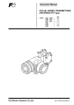
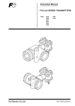
Instruction Manual
FCX-A@ SERIES TRANSMITTERS
(FOUNDATION FIELDBUS Type)
TYPE:
FDA FDW
FDB FDX
FDC FDY
FDD
FDE
FDG
INF-TN4FCXA2FB-E
INTRODUCTION
Thank you very much for your purchase of the Fuji FCX-A2 Series Transmitters (FOUNDATION
FIELDBUS Type).
• First read this instruction manual carefully until an adequate understanding is required, and then
proceed to installation, operation and maintenance of the FCX-A2 Series transmitter.
• The specifications of the transmitter will be changed without prior notice for further product improvement.
• Modification of the transmitter without permission is strictly prohibited. Fuji will not bear any responsibility for a trouble caused by such a modification.
• This instruction manual should be kept by a person who is actually using the transmitter.
• After reading this manual, keep it at a place easier to access.
• This manual should be delivered to the end user without fail.
• For detail specifications and outline diagrams, refer to the specifications furnished separately.
The product conforms to the requirements of “the Electromagnetic compatibility Directive 89/336/EEC” and “Equipment and
protective systems intended for use in potentially explosive atmospheres Directive 94/9/EC” as detailed within the technical
construction file number TN513035. The applicable standards
used to demonstrate compliance are :
EN 61326: 1997
Class A
EN 61326: 1997
Annex A
Manufacturer:
Type:
Date of manufacture:
Product nationality:
Fuji Electric Instrumentation Co., Ltd.
Described in nameplate on main frame (see Page iv)
Described in nameplate on main frame
Japan
© Fuji Electric Sysems Co., Ltd. 2004
Request
Issued in June, 2004
• Transcription of a part or the whole of this manual without permission is
prohibited.
• The contents of this manual are subject to change without prior notice.
INF-TN4FCXA2FB-E
i
CAUTION ON SAFETY
First of all, read this “Caution on Safety” to ensure correct operation of the transmitter.
• The cautionary descriptions listed here contain important information about safety, so they should be
observed without fail. Those safety precautions are classified into ranks "DANGER" and "CAUTION".
DANGER
Wrong handling may cause a dangerous situation, in which there is a
risk of death or heavy injury.
CAUTION
Wrong handling may invite a dangerous situation, in which there is a
possibility of medium-level trouble or slight injury or only physical
damage is predictable.
On items listed under “
CAUTION ”, they may also lead to serious accidents depending on circumstances, and must be fully observed.
• The signs of prohibition and indication are explained in the following.
PROHIBITION
General items which pertain to prohibition (DO NOT)
INDICATION
General items which pertain to user’s action
Installation and Piping
DANGER
• Non-explosion-proof transmitter must not be used in a place with explosive gases to prevent serious
accidents such as explosion, fire, etc.
CAUTION
• The transmitter is heavy. Be careful when handling it.
• The transmitter should be installed in a place that meets the operating conditions shown in DS sheet
or this instruction manual.
• Install the transmitter according to the instruction manual. Improper installation may lead to the
cause of fall, trouble or incorrect operation.
• When installing, make sure that the transmitter interior is free from cable chips and other foreign
objects to prevent fire, trouble, or incorrect operation.
• When power is ON, do not change the position of the field indicator in an explosion-proof area.
• When power is ON, do not change the position of the amplifier unit in an explosion-proof area.
• When power is ON, do not change the angle of the indicator.
• Main valve used for piping should be selected with the maximum pressure of the process taken into
account (piping parts such as main valve, etc. should be furnished by user). If the main valve and
other parts do not meet the rating, it may result in leakage of gas or liquid which could lead to hazard.
• Pressure pipes to be used must meet the temperature/pressure rating.
ii
INF-TN4FCXA2FB-E
Wiring
DANGER
• On explosion-proof type transmitter, its wiring work must be performed according to the required
laws and regulations. Incorrect wiring may cause explosion, fire or other serious accidents.
CAUTION
• Before making wiring work, be sure to turn OFF the main power to prevent electric shocks.
• Use wiring materials of correct rating to prevent fire accidents.
• Connect a power source of correct rating to prevent fire accidents.
• The transmitter should be grounded as specified to prevent electric shocks or incorrect operation.
• After installing the transmitter, firmly close the covers of the amplifier unit and terminal box. If not,
rain water enter the transmitter which may result in trouble or incorrect operation.
Adjustment
DANGER
• When using a flame-proof transmitter, do not connect HHC to the transmitter terminals and junction
terminals.
Replacement of Maintenance Parts
DANGER
• When removing an explosion-proof transmitter, turn OFF the main power, then disconnect the piping
and wiring. Do not remove it when the power is ON to prevent serious accident such as explosion,
fire, etc.
INF-TN4FCXA2FB-E
iii
CAUTIONS ON USE
Be sure to observe the following instructions
Storage for a long period
Store the transmitter in a dry room at normal temperature and humidity.
Keep protection caps in place at the conduit connection and process connection.
For installation, select an appropriate place
Site at location with minimal vibration, dust and corrosive gas
At a place allowing an adequate space for checkup
Site at location large enough to allow maintenance and checking.
Mounting angle
Mount to a pipe horizontally or vertically.
Attention to overload
Do not apply a pressure outside the specified range.
Other
Besides the above, be sure to observe the cautions given in this manual.
CONFIRMATION OF YOUR SPECIFICATION
The instrument nameplate as shown below is attached at the amplifier unit of this transmitter. Before use,
make sure the contents of the nameplate agree exactly with your specifications.
Tag No.
Transmitter
Type
Output scale
P.Supply
Range Limit
Out.
M.W.P.
Ser. No.
Mfd.
Fuji Electric Systems Co., Ltd.
iv
Made in Japan
TK4H3107
INF-TN4FCXA2FB-E
CONTENTS
INTRODUCTION ....................................................................................................................... i
CAUTION ON SAFETY ............................................................................................................ ii
CAUTIONS ON USE ............................................................................................................... iv
CONFIRMATION OF YOUR SPECIFICATION .................................................................... iv
CONTENTS ............................................................................................................................... v
1. OUTLINE ........................................................................................................................... 1
2. OPERATING PARTS AND THEIR FUNCTIONS ............................................................. 2
3. OPERATION AND SHUTDOWN ..................................................................................... 4
3.1 Preparation for operation ................................................................................................................... 4
3.2 Operation ............................................................................................................................................ 5
3.3 Shutdown ............................................................................................................................................ 6
4. FIELDBUS .......................................................................................................................... 8
4.1 Outline ............................................................................................................................................... 8
4.2 Logical structure of field device ........................................................................................................ 8
4.2.1 VFD for system management ....................................................................................................... 8
4.2.2 Function block VFD ..................................................................................................................... 8
4.3 Necessary equipment ........................................................................................................................ 10
4.4 Setting of host system ...................................................................................................................... 11
4.5 Setting of DD (Device Description) ................................................................................................ 12
4.6 Configuration .................................................................................................................................... 12
4.6.1 Network parameter setting ......................................................................................................... 13
4.6.2 Function block schedule ............................................................................................................. 13
4.6.3 Tag and address setting .............................................................................................................. 14
4.6.4 Virtual Communication Relationship ........................................................................................ 14
4.6.5 Setting of Function Block VFD ................................................................................................. 16
4.6.6 Parameters of AI function block ................................................................................................ 21
4.6.7 Parameters of transducer block .................................................................................................. 22
4.6.8 Parameters of resource block ..................................................................................................... 22
4.6.9 Alarms and events ...................................................................................................................... 23
5. ADJUSTMENT AND SETTING ....................................................................................... 25
5.1 Method of adjustment on host system ............................................................................................ 25
5.1.1 Zero adjustment on host system ................................................................................................. 25
5.1.2 Span adjustment on host system ................................................................................................ 25
5.2 Zero adjustment ............................................................................................................................... 26
5.3 How to set the output mode ............................................................................................................ 27
5.4 Setting of low flow cut point ........................................................................................................... 27
5.5 Damping adjustment ........................................................................................................................ 27
5.6 Setting of burnout direction ............................................................................................................. 27
5.7 Locking of external adjustment function ......................................................................................... 28
5.8 Setting of display on digital indicator ............................................................................................. 28
5.8.1 Setting method ............................................................................................................................ 28
5.9 Setting of output scale ...................................................................................................................... 29
5.10 Simulation function ........................................................................................................................ 29
INF-TN4FCXA2FB-E
v
6. MAINTENANCE .............................................................................................................. 30
6.1 Periodic inspection .......................................................................................................................... 30
6.2 Troubleshooting ................................................................................................................................ 31
6.3 Replacement of parts ........................................................................................................................ 32
7. INSTALLATION AND PIPING ........................................................................................ 39
7.1 Installation ........................................................................................................................................ 39
7.2 Piping ............................................................................................................................................... 42
7.2.1 Piping of differential pressure and flow transmitter (type: FDC.) ...................................................... 42
7.2.2 Piping of pressure and absolute pressure transmitter (types: FDG, FDA) ................................ 46
7.2.3 Piping of level transmitter (types: FDE, FDY) ........................................................................ 48
7.2.4 Piping of remote seal type differential pressure transmitter (types: FDD, FDX) ............................ 51
7.2.5 Piping of remote seal type pressure transmitter (types: FDB, FDW) ..................................... 54
8. WIRING ............................................................................................................................ 58
8.1 Wiring procedure .............................................................................................................................. 58
8.2 Configuration of fieldbus connection .............................................................................................. 60
8.3 Grounding ......................................................................................................................................... 60
Appendix 1
Appendix 2
Appendix 3
Appendix 4
Appendix 5
Appendix 6
vi
CALIBRATION ................................................................................................... 61
PARAMETERS OF BLOCKS ............................................................................ 64
UNIT CODES ..................................................................................................... 66
HAZARDOUS LOCATION INSTALLATION INFORMATION ........................ 67
DISPLAY UNIT CODES .................................................................................... 70
CABLES FOR H1 FIELDBUS ........................................................................... 71
INF-TN4FCXA2FB-E
1. OUTLINE
The FCX-A2 series transmitter (FOUNDATION FIELDBUS type) detects the differential pressure or
pressure of various fluids, converts it into a fieldbus signal and transmits it.
Specifications standardized by the FOUNDATION FIELDBUS are adopted for the FOUNDATION
FIELDBUS type of FCX-A2 series, whereby an interchangeability with products of our or other companies
is ensured.
The AI function block is installed for carrying out differential pressure or pressure calculation.
Principle
The operating principle of the FCX-A2 series transmitter is shown in the block diagram below. The
input pressure is changed into an electrostatic capacitance in the detecting unit. The change proportional to the pressure undergoes amplification and calculation in the transmitting unit, and is then
output to the fieldbus.
Displacement
Input
pressure
Diaphragm
Sensor
Detecting unit
INF-TN4FCXA2FB-E
Capacitance
change
Measuring
circuit
Operational
amplification
circuit
Fieldbus
Amplifier unit
1
2. OPERATING PARTS AND THEIR FUNCTIONS
FCX-A2
2 Series transmitter
Terminal unit
Amplifier unit
–
CK
+
CK
–
Simulation switch
+
Detecting unit
Process connection
Field indicator connector
Feild indicator
OUT
DISP
FLX
Vent/drain
plug
Electronics
unit
%
SPAN
ZERO
abs
External adjustment
screw
2 Series transmitter
Description of FCX-A2
Part name
Description
Detecting unit
Detects pressure, differential pressure or level of fluid.
Amplifier unit
Converts the detected signal into an output signal.
Vent/drain plug
Used for gas discharge or draining.
(Attention should be paid under a high pressure.)
Process connection
Connects impulse pipes from the process.
Conduit connection
Connects the output cable.
External adjustment screw
Adjusts zero.
Terminal box
Used for connecting input/output cable and grounding cable.
Amplifier unit
Part name
Description
Field indicator connector
Used for connecting the field indicator.
Field indicator (option)
A digital field indicator can be mounted.
Simulation switch
Used when a simulation function (function block) is resorted to.
Terminals
Symbol
+, –
CK+, CK–
Description
Connects the cable to the fieldbus.
Not used for the FOUNDATION FIELDBUS type.
Used for grounding within the terminals.
2
INF-TN4FCXA2FB-E
Mode and status indicating functions for field indicator
OUT
DISP
%
FIX
SPAN
ZERO
abs
Mode and status indications
Mode
%
ZERO
DISP
abs
–
N
INF-TN4FCXA2FB-E
When indicated
When not indicated
% output (unused)
Actual scale
External zero adjustment possible
External zero adjustment impossible
Field indicator
Field indicator LIN display
display
Transmitter operating (Flicker)
Transmitter not operating
Absolute pressure
Gage pressure
Output value < Zero
Output value
Zero
(Display at particular unit selection)
3
3. OPERATION AND SHUTDOWN
3.1 Preparation for operation
Before operating the transmitter, be sure to perform the following checks and procedures. On zero
point check or zero adjustment in hazardous area, do not open terminal cover.
Use the transmitter indicator and the external adjustment screw.
Preparation procedure
(1) Check for liquid or gas leakage from the process connection, etc. by applying soapy water or the like.
(2) Check the signal wiring according to the “Terminal
block connection diagram” shown in 8.1.
(3) Vent gas from the transmitter in the case of liquid
measurement.
Important
When the plant requires chemical cleaning at the start of operation, be sure to close the
valve of the transmitter to prevent entry of cleaning liquid into the pressure receiving
unit.
(4) Perform zero point adjustment.
Zero point adjustment
Turn on the fieldbus.
Watch the host system for checking the output signal of the transmitter.
After ten minutes or longer, adjust the transmitter output to zero in the following manner.
Zero adjustment
(1) Adjustment by zero adjustment screw
Adjust zero point of the transmitter to a specified
zero point output by turning the zero adjustment
screw.
Decrease
Increase
(2) Adjustment by host instrument
Refer to “zero and span adjustment” on the host
system in 5.1.
Fine adjustment : turning slowly
Rough adjustment : turning quickly
Important
4
1. After adjustment of the transmitter, it should be kept energized for about 10 seconds
to write the adjustment results into memory.
2. Use a blade-edge screwdriver for adjusting the zero adjustment screw.
INF-TN4FCXA2FB-E
3.2 Operation
(1) Operation of pressure transmitter
Open the valve slowly to apply a pressure. When a pressure is applied, the transmitter is set in
the operating status.
Open
(2) Operation of differential pressure transmitter
Set the operating status by manipulating the manifold valve.
Stop valve
on the low
pressure side
Open
Equalizing
valve
Make sure the equalizing valve is open.
Stop valve
on the high
pressure side
Open
Open the stop valve on the high pressure side
slowly.
Close
Close the equalizing valve.
INF-TN4FCXA2FB-E
5
Open
Finally, open the stop valve on the low pressure side slowly.
Check of operating status
Use a field indicator, or host instrument to check the operating status.
3.3 Shutdown
(1) Shutdown of pressure transmitter
Close the valve slowly to stop applying a pressure. The transmitter is set in the measurement
stop status.
Close slowly.
6
INF-TN4FCXA2FB-E
(2) Shutdown of differential pressure transmitter
Set the shutdown status by manipulating the manifold valve.
Close the stop valve on the high pressure side (H side)
slowly.
Close
Open
Open the equalizing valve.
Close
Close the stop valve on the low pressure side (L side)
slowly.
Important
Before a long shutdown, discharge the process fluid and drain completely from the transmitter.
This is to protect the transmitter from freezing, corrosion, etc.
INF-TN4FCXA2FB-E
7
4. FIELDBUS
4.1 Outline
The fieldbus type is a bidirectional digital communication method for field devices adopted instead of
the conventional analog communication of 4 to 20 mA.
Specifications standardized by the FOUNDATION FIELDBUS are adopted for the FOUNDATION
FIELDBUS type of FCX-A2 series, whereby an interchangeability with fieldbus products of our or
other companies is ensured.
One AI function block is installed for different pressure or pressure calculation.
4.2 Logical structure of field device
In the fieldbus version, two virtual field devices (VFD) exist, each having the functions given below.
4.2.1 VFD for system management
• Sets node address* and PD tag* (device tag name) necessary for communication.
• Controls the execution of the function block.
• Manages the parameters and communication resource (Virtual Communication Relationship:
VCR) necessary for communication.
* Individual address and tag name are necessary for the field device in order that it can be connected to the fieldbus.
4.2.2 Function block VFD
(1) Resource block
• Manages the hardware statuses.
(2) Transducer block
• Converts the sensor output into a pressure signal, and transmits it to the AI function block.
(3) AI function block
The function block of the Fieldbus Association version is a function model common to measurement and control.
There, functions used for field device and control system such as PID control, analog input
and analog output are provided for common use.
The FCX-A2 series is equipped with an analog input (AI) function block. This block receives data measured by the transducer block, and subjects the data to the following processing.
• Scaling
• Square root extraction
• Damping
• Alarm generation
8
INF-TN4FCXA2FB-E
Fig. 4-1 shows the internal configuration of the AI function block.
AI function block
Calculation
Scaling
Square root
extraction
CHANNEL
OUT
Damping
Simulate
Fig. 4-1 AI function block.
Logical structure of field device
FCX-A2
(FOUNDATION
FIELDBUS type)
VFD for system management
PD tag (device tag)
Communication parameter
Node address
Virtual communication
relationship
Function block
schedule
Function block VFD
AI function block
Block tag
Block tag
Parameter
Parameter
Sensor
Transducer block
Resource block
Block tag
Parameter
Fig. 4-2 Logical structure of field device
INF-TN4FCXA2FB-E
9
4.3 Necessary equipment
In order that a device of FOUNDATION FIELDBUS type can be used, the following equipment are
required.
• Fieldbus power supply
Use a power supply dedicated to the fieldbus of a current capacity over the maximum current consumption of all connected devices. You cannot use the conventional DC power supply. (Recommended power supply: Relcom make FCS-BPC series fieldbus power conditioner.)
• Terminators
Two terminators dedicated to the fieldbus are required. On H1 fieldbus, a terminator with 100 Ω
and 5 µF connected in series is used on each of its ends. The host system side may incorporate one.
Contact the supplier you purchased the host system from.
• Host system
Used for measurement and control of the fieldbus device. For details, refer to the instruction manual
of the host system manufacturer.
• Cables
Used for connecting the devices. As an instrumentation cable, we recommend you to use type A
cable of the FOUNDATION FIELDBUS. For the cable specifications, refer to Appendix 6
“CABLES FOR H1 FIELDBUS”.
For connection of the equipments, refer to Fig. 4-3.
Host system
Terminator
Terminator
Power supply for fieldbus
FCX-A2
(FOUNDATION
FIELDBUS type)
Fig. 4-3 Connection of equipments
Important
10
For the FOUNDATION FIELDBUS type, the CHECK terminal cannot be used.
The current check meter cannot be connected unlike the conventional analog output type.
INF-TN4FCXA2FB-E
4.4 Setting of host system
In order that the fieldbus can be used, the host system should be set as follows.
CAUTION
Do not turn off immediately after setting of the transmitter. It should be kept energized for about
10 seconds to store the data into the memory.
If power is turned off soon after setting change, the parameter settings may not be renewed but
remain as last.
Table 4-1 Setting parameters
Description
Parameter name
Slot-Time(ST)
Select 5 or more.
Minimum-Inter-PDU-Delay(MID)
Select 10 or more.
Maximum-Response-Delay
-Slot-Time(MRD)
Carry out setting so that MRD × ST will be equal to or greater
than 20.
First-Unpolled-Node(FUN)
Limits the range of addresses the host system accesses.
Set the FUN to the start address of the range that the host
instrument need not access.
Number-of-consencutive
-Unpolled-Node(NUN)
Sets the range of addresses the host system does not use.
The host instrument does not access the range from the
address to which FUN was set to the address to which NUN
was set.
0x00
0x10
Unused
Link master device
FUN
Address range
link master device does
not access
FUN+NUN
FCX-A2
Basic device
(0xF0)
0xF7
0xF8
Default device address
0xFB
Temporarily connected
device address
0xFF
Notes
1. Link master device : Has a function of controlling the fieldbus
(link master function).
2. Basic device
: Does not have a function of controlling the fieldbus.
Fig. 4-4 Address range
INF-TN4FCXA2FB-E
11
Unless otherwise specified, settings prior to delivery are as follows.
• PD tag: EFB-001.
• Node address: 240 (0xF0).
• Device ID: 0003090032******* (0003090032 is followed by 7 numerics and/or alphabets)
Unless the FCX-A2 (FOUNDATION FIELDBUS type) is detected on the fieldbus, check the address
used by the host system against the specified range and power polarities.
Unless otherwise specified by you, default PD tag and node address are set prior to delivery. If 2
devices or more are simultaneously connected in default statuses, only one device is detected. In such
a case, set the node address and PD tag every time each of devices is connected one by one.
4.5 Setting of DD (Device Description)
If the host system supports DD (Device Description), DD should be set for the FCX-A2 on the host
system. Check whether or not the directory for setting the DD of the host system is followed by the
directory below.
000309¥0032 (000309 corresponds to Fuji’s manufacturer number, and 0032 is device number for
FCX-A2)
Unless this directory is present, create a directory.
To the above directory, copy the DD file (0101.ffo,0101.sym) supplied separately.
When DD has been set, all parameters of FCX-A2 can be displayed.
It is also possible to carry out an off-line configuration using a capability file (CFF).
4.6 Configuration
On the fieldbus, several field devices are connected. Therefore, all of them should be covered by
settings in the following procedure.
(1) Network parameter setting
Set the tag, node address and communication parameters of the device to connect.
(2) Function block linking
Set the link of function blocks.
(3) Tag and address settings
Set the PD tag and node address for each of fieldbus devices.
(4) Communication resource
Set the link between VCR (Virtual communication relationship) and function blocks.
(5) Block setting
Set the link object, trend object and view object.
12
INF-TN4FCXA2FB-E
4.6.1 Network parameter setting
Before connecting fieldbus devices, set the network parameters. Assign node address and PD tag
to all devices. The PD tag is the same as used for devices heretofore. The node address is used
for communication, and its settable range is 16 to 247 (0x10 to 0xf7). Set the node address within
the range shown in Fig. 4-3.
After determining the node address and PD tag for all devices, set the following network parameters for the link master device.
• First-Unpolled-Node (FUN)
• Number-of-consecutive-Unpolled-Node (NUN)
• Slot-Time (ST)
• Minimum-Inter-PDU-Delay (MID)
• Maxmum-Response-Delay-Slot-Time (MRD)
Determine the FUN and NUN according to how many devices to connect.
Set the ST, MID and MRD to the most unfavorable values of devices to connect.
For the FCX-A2, carry out settings so that ST will be 5 or more, MID 10 or more, and MRD 20 or
more.
4.6.2 Function block schedule
Connect the input/output of the function blocks. For the FCX-A2, connect the OUT parameter of
AI function block.
The connected function block may be executed together with other blocks timed with the communication schedule. In such a case, set the schedule as given in Table 4-2.
Table 4-2 Execution schedule for function blocks
Setting contents (setting prior to delivery)
Parameter name
MACROCYCLE_DURATION
Control or measurement cycle (macrocycle) in increments of
1/32 msec (3200 = 1 sec).
FB_START_ENTRY.1
Startup time for AI function block in terms of lapse of time from
macro cycle in increments of 1/32 msec (0 = 0 msec).
FB_START_ENTRY.2 to 10
Unused.
For execution of AI function block, it takes 100 msec maximum. Arrange the communication
schedule so that the next function block will be connected only after lapse of this time.
INF-TN4FCXA2FB-E
13
4.6.3 Tag and address setting
Unless otherwise specified, the PD tag and node address are set prior to delivery in default at
EFB-001 and 240 (0xF0 hex), respectively. For each of devices, determine and set the node
address and PD tag.
4.6.4 Virtual Communication Relationship
For setting the communication function, you should change the data of VFD for system management. Set the VCR (Virtual Communication Relationship) for designating the communication
destination and resource. The FCX-A2 has 20 items of VCR. Except the first one used for
system management, they can be changed. VCR of the FCX-A2 includes 3 items below.
• Server (QUB) type VCR
For 1-to-1 communication answering the communication request from the host in an aperiodic
manner. Used for access to tuning parameter, down-load/up-load of device data, etc.
• Source (QUU) type VCR
For 1-to-N communication among devices on the fieldbus in an aperiodic manner. If an event/
trend notification has occurred on a device, data is sent to a device subjected to a configuration.
• Publisher (BNU) type VCR
Periodically sends the output of AI function block to another block.
Each connection information has parameters given in Table 4-3.
Do not change any single parameter but the parameters of the entire connection information in
batch to avoid an inconsistent action.
14
INF-TN4FCXA2FB-E
Table 4-3 Virtual Communication Relationship (VCR_STATIC_ENTRY)
Sub-index
Description
Parameter name
1
FasArTypeAndRole
Kind of VCR to use.
0x32: Server type
0x44: Report distribution type
0x66: Publisher type
2
FasDllLocalAddr
Address for designating a VCR in FCX-A2.
3
FasDiiConfiguredRemote
Addr
Node address of communication destination and address for
designate its VCR.
4
FasDllSDAP
Communication quality.
0x2B: Server
0x01: Alert
0x03: Trend
0x91: Publisher/Subscriber
5
FasDllMaxConfirmDelay
OnConnect
Maximum time in msec to wait for an answer from the opposite party
in order to establish a communication connection.
6
FasDllMaxConfirmDelayOn
Data
Maximum time in msec to wait for an answer from the opposite party
to a request of data.
7
FasDllMaxDlsduSize
Maximum size of data part. Designate 256 for server or trend, and
64 for others.
8
FasDllResidualActivity
Supported
Whether to supervise the connection or not. Select 0xff for server
type only.
9
FasDllTimelinessClass
Unused.
10
FasDllPublisherTimeWindow
Size
Unused.
11
FasDllPublisherSynchronizaing
Dlcep
Unused.
12
FasDllSubscriberTimeWindow
Size
Unused.
13
FasDllSubscriberSyncronizaing
Dlcep
Unused.
14
FmsVfdId
VFD of the FCX-A2 to use.
(0x012C: System management VFD, 0x0001: Function block VFD.)
15
FmsMaxOutstandingServer
Calling
Select 0 for server. Not used for other purposes.
16
FmsMaxOutsatndingSever
Called
Select 1 for server. Not used for other purposes.
17
FmsFeaturesSupported
Service type of application layer.
INF-TN4FCXA2FB-E
15
4.6.5 Block setting
Object of function block VFD.
(1) Link object
Connects the data sent spontaneously by a function block to the Virtual Communication
Relationship (VCR). The FCX-A2 has 15 link objects. Table 4-4 gives parameters of a link
object. Do not change any single parameter but the parameters of the entire connection
information in batch to avoid an inconsistent operation.
Table 4-4 Link object
Sub-index
Description
Parameter name
1
LocalIndex
Parameter index of function block to connect. Select 0 for trend or
alarm.
2
VcrNumber
Index of VCR to connect.
3
RemoteIndex
Unused (0).
4
ServiceOperation
Select one of the following.
0: Undefined (unused)
2: Publisher
6: Trend
7: Alert
5
StaleCountLimit
Unused.
(2) Trend object
It is possible to automatically send the trend from a function block. The FCX-A2 has one
analog type trend object. The trend object has parameters given in Table 4-5. Out of them,
the first 4 parameters should be set.
Table 4-5 Trend object
Sub-index
Description
Parameter name
1
Block Index
Function block index (508).
2
Parameter Relative Index
Index of parameter to take a trend from in a value relative to the top of
function block. It falls into OUT parameter in case of the FCX-A2.
OUT: 8
3
Sample Type
Select a method of taking a trend from the following.
1: Sample at an execution of function block
2: Sample an average
4
Sample Interval
Set the sample interval in increments of 1/32 msec and in integer
multiple of execution cycle of function block.
5
Last Update
The last time of sample.
6 to 21
List of Status
Status part of sampled parameter.
21 to 37
List of Sample
Data part of sampled parameter.
16
INF-TN4FCXA2FB-E
(3) View object
Used for accessing data upon grouping the block parameters. 4 view objects each are supported by the FCX-A2 for resource block, transducer block and function block as given in
Tables 4-6 to 4-8. Values in the tables denote byte counts of each parameter.
Table 4-6 View object of resource block
Relative index
INF-TN4FCXA2FB-E
Parameter name
1
ST_REV
2
TAG_DESC
VIEW1 VIEW2 VIEW3 VIEW4
2
2
2
2
3
STRATEGY
2
4
ALERT_KEY
1
5
MODE_BLK
4
4
6
BLOCK_ERR
2
2
7
RS_STATE
1
1
8
TEST_RW
9
DD_RESOURCE
10
MANUFAC_ID
4
11
DEV_TYPE
2
12
DEV_REV
1
13
DD_REV
14
GRANT_DENY
15
HARD_TYPES
16
RESTART
17
FEATURES
18
FEATURE_SEL
19
CYCLE_TYPE
1
2
2
2
2
2
20
CYCLE_SEL
21
MIN_CYCLE_T
4
22
MEMORY_SIZE
2
2
23
NV_CYCLE_T
4
24
FREE_SPACE
4
25
FREE_TIME
26
SHED_RCAS
27
SHED_ROUT
28
FAULT_STATE
29
SET_FSTATE
30
CLR_FSTATE
31
MAX_NOTIFY
32
LIM_NOTIFY
4
4
4
4
1
1
1
1
33
CONFIRM_TIME
4
34
WRITE_LOCK
1
35
UPDATE_EVT
17
Relative index
Parameter name
36
BLOCK_ALM
37
ALARM_SUM
8
8
38
ACK_OPTION
2
39
WRITE_PRI
1
40
WRITE_ALM
41
ITK_VER
42
ERROR_COUNT
43
RESET_ERR_COUNT
44
WD_COUNT
45
DEV_ID
46
W_PROTECT
47
ALERM_SIMULATE
48
VERSION
49
DEVICE_SN
50
DEVICE_PILC
Total No. of bytes
18
VIEW1 VIEW2 VIEW3 VIEW4
2
22
30
22
31
INF-TN4FCXA2FB-E
Table 4-7 View object of transducer block
Relative index
Parameter name
1
ST_REV
2
2
2
2
2
TAG_DESC
3
STRATEGY
2
4
ALERT_KEY
1
5
MODE_BLK
4
4
6
BLOCK_ERR
2
2
7
UPDATE_EVT
8
BLOCK_ALM
9
TRANSDUCER_DIRECTORY
10
TRANSDUCER_TYPE
2
11
XD_ERROR
1
12
COLLECTION_DIRECTORY
13
PRIMARY_VALUE_TYPE
14
PRIMARY_VALUE
15
PRIMARY_VALUE_RANGE
16
CAL_POINT_HI
4
17
CAL_POINT_LO
4
18
CAL_MIN_SPAN
19
CAL_UNIT
20
SENSOR_TYPE
21
SENSOR_RANGE
22
SENSOR_SN
23
SENSOR_CAL_METHOD
24
SENSOR_CAL_LOC
25
SENSOR_CAL_DATE
26
SENSOR_CAL_WHO
27
SENSOR_ISOLATOR_MTL
28
SENSOR_FILL_FULID
29
SECONDARY_VALUE
30
SECONDARY_VALUE_UNIT
31
BURNOUT_SET
32
PV_SENSOR_INFO
33
OUTPUT_INFO
34
CAL_DATA
35
CAL_UPPER
36
CAL_LOWER
37
DYNAMIC_INFO
38
LOCAL_KEY
39
CELL_BODY_NUMBER
40
LCD_COMMAND
41
LCD_DISP
42
LCD_SEG_DATA
43
MEM_COMMAND
44
MEM_ACCESS
Total No. of bytes
INF-TN4FCXA2FB-E
VIEW1 VIEW2 VIEW3 VIEW4
2
2
2
1
2
5
5
5
5
2
21
16
21
7
19
Table 4-8 View object of AI function block
Parameter name
Relative index
1
ST_REV
2
2
2
2
2
TAG_DESC
3
STRATEGY
2
4
ALERT_KEY
1
5
MODE_BLK
4
4
6
BLOCK_ERR
2
2
7
PV
5
5
8
OUT
5
5
9
SIMULATE
10
XD_SCALE
11
11
OUT_SCALE
11
2
12
GRANT_DENY
13
IO_OPTS
2
14
STATUS_OPTS
2
15
CHANNEL
2
16
L_TYPE
1
17
LOW_CUT
4
18
PV_FTIME
4
19
FIELD_VAL
20
UPDATE_EVT
21
BLCCK_ALM
5
5
8
8
22
ALERM_SUM
23
ACK_OPTION
2
24
ALERM_HYS
4
25
HI_HI_PRI
1
26
HI_HI_LIM
4
27
HI_PRI
1
28
HI_LIM
4
29
LO_PRI
1
30
LO_LIM
4
31
LO_LO_PRI
1
4
32
LO_LO_LIM
33
HI_HI_ALM
34
HI_ALM
35
LO_LIM
36
LO_LO_ALM
Total No. of bytes
20
VIEW1 VIEW2 VIEW3 VIEW4
31
26
31
46
INF-TN4FCXA2FB-E
4.6.6 Parameters of AI function block
Settings of parameters of the AI function block can be read, and they can be set on the host
system. For main block parameters supported by the FCX-A2, refer to Appendix 2 “PARAMETERS OF BLOCKS”. Here, important parameters will be explained.
MODE_BLK
Determines the mode of the AI function block.
This parameter consists of 4 elements: Target, Actual, Permitted and Normal.
Target is an element by which the operator sets the operation mode of the AI function block.
This element can be written.
Actual indicates the actual operation mode of the block, and is used for read only. If requirements were met, Actual works the same as Target. Actual may differ from Target for several
reasons.
Permitted indicates which mode is allowed in this function block. Normal is an element by
which the operator sets a mode where this function block operates normally. Permitted and
Normal are elements where writing is available.
On the AI function block, Out of Service, Manual or Auto is selectable. In the Out of Service
mode, the AI function block carries out no execution. In the Manual mode, the AI function
block carries out an execution, but last value is not affected by its output and remains as it is.
The output can be rewritten from the host instrument. In the Auto mode, the AI function
block carries out an execution, and updates the output. This is a normal measurement mode.
XD_SCALE
Used for setting values corresponding to 0% and 100% of the input from the transducer block
and industrial value unit. A calibrated range is set prior to delivery. The unit is fixed at kPa.
OUT_SCALE
Used for setting values corresponding to 0% and 100% of the output, and industrial value
unit.
L_TYPE
Used for designating an operational method of the AI function block. If Direct was selected,
the input from the transducer block directly affects the output. If Indirect was selected,
scaling is made according to XD_SCALE and OUT_SCALE, and the output is affected. If
Indirect Sq. Root was selected, scaling is made by XD_SCALE, then square root extraction
is made, scaling is made by OUT_SCALE, and the output is affected.
PV_FTIME
Used for setting a damping time constant in seconds. Select a value 0 or more.
HI_HI_PRI,HI_PRI,LO_PRI,LO_LO_PRI
Used for setting the priority of process alarms. Selecting 3 or more delivers an alarm. Setting prior to delivery is 0.
INF-TN4FCXA2FB-E
21
HI_HI_LIM,HI_LIM,LO_LIM,LO_LO_LIM
Used for setting threshold values at which process alarms will occur. Settings prior to delivery are positive infinity and negative infinity so that no alarms will occur.
4.6.7 Parameters of transducer block
The transducer block has parameters peculiar to differential pressure and pressure measurements.
For main block parameters available by the FCX-A2, refer to Appendix 2 “PARAMETERS OF
BLOCKS”. Here, important parameters will be explained.
CAL_POINT_HI
The high limit (100%) of the calibrated point is set.
CAL_POINT_LO
The low limit (0%) of the calibrated point is set.
CAL_DATA
Used for a calibration. For a calibration with CAL_POINT_LO, select Calibration enable
and Low Trim. Or, for a calibration with CAL_POINT_HI, select Calibration enable and
Upper Trim. Or, for adjustment with industrial value of 0, select Calibration enable and Zero
Calibration.
4.6.8 Parameters of resource block
The resource block has parameters related to the resources of the device. For main block parameters available by the FCX-A2, refer to Appendix 2 “PARAMETERS OF BLOCKS”. Here,
important parameters will be explained.
ERROR_COUNT
Errors produced at device communications are counted.
RESET_ERR_COUNT
Used to clear ERROR_COUNT.
W_PROTECT
Controls rewriting parameters peculiar to the FCX-A2. Rewriting is unavailable if True is
selected, or available if False is selected.
22
INF-TN4FCXA2FB-E
4.6.9 Alarms and events
The FCX-A2 can report the following alarms and events.
Analog alarm: Produced when a process variable has exceeded a limit.
It occurs if the variable is beyond any of HI_HI_LIM, HI_LIM, LO_LIM,
LO_LO_LIM of the AI function block.
Discrete alarm: Produced when any block has detected an anomaly.
Alarts produced in different blocks are as follows.
(1) Resource block
Block alarm
Produced when:
Out of Service
The Out of Service mode has been posted in the
resource block.
Simulation Active
The simulation switch has been turned on.
OFF status ON status
Simulation switch
(2) Transducer block
Block alarm
Produced when:
Out of Service
The Out of Service mode has been posted in the
resource block.
Sensor error
(XD_ERROR: I/O Failure)
The sensor has become abnormal
(display output: FL-1).
Circuit error or memory error
(XD_ERROR: Electronics Failure)
The internal circuit has troubled
(display output: Circuit error FL-2, memory error FL-3).
Temperature error
(XD_ERROR: General Err)
The temperature of the detecting unit has gone beyond
the range of -45°C to +90°C.
INF-TN4FCXA2FB-E
23
(3) AI function block
Block alarm
24
Produced when:
Out of Service
The Out of Service mode has been posted in the
resource block.
Simulation Active
The simulation function is enabled.
Input Failure
The transducer input is abnormal.
Configuration error
The unit of XD_SCALE of the AI function block does not
coincide with that of PRIMARY_VALUE_RANGE.
INF-TN4FCXA2FB-E
5. ADJUSTMENT AND SETTING
5.1 Method of adjustment on host system
The transmitter can be adjusted on the host system upon setting the block parameters.
5.1.1 Zero adjustment on host system
Zero adjustment is available while an input is being applied.
(1) How to set a calibration point (adjustment input)
The adjustment input (calibration point) is set as follows. Set the TARGET of MODE_BLK
of the transducer block to Out of Service (0x80). Set the CAL_POINT_LO to an adjustment
input value in the unit displayed at CAL_UNIT.
After the end of setting, return the TARGET of MODE_BLK to Auto (0x08).
(2) Set W_PROTECT of the resource block to False (0x00) to allow Fuji’s original parameter to
be written.
(3) Set Command of CAL_DATA of the transducer block to Low_Trim and Calibration enabled
(0x82), and write the parameter setting. Then, an adjustment will be executed at an adjustment input.
(4) After the end of adjustment, set W_PROTECT of the resource block to True (0xff) to protect
the original parameter setting from being changed.
5.1.2 Span adjustment on host system
Span adjustment is available while an input is being applied.
(1) How to set a calibration point (adjustment input)
The adjustment input (calibration point) is set as follows. Set the TARGET of MODE_BLK
of the transducer block to Out of Service (0x80). Set the CAL_POINT_HI to an adjustment
input value in the unit displayed at CAL_UNIT.
After the end of setting, return the TARGET of MODE_BLK to Auto (0x08).
(2) Set W_PROTECT of the resource block to False (0x00) to allow Fuji’s original parameter to
be written.
(3) Set Command of CAL_DATA of the transducer block to Upper_Trim and Calibration enabled (0x84), and write the parameter setting. Then, an adjustment will be executed at an
adjustment input.
(4) After the end of adjustment, set W_PROTECT of the resource block to True (0xff) to protect
the original parameter setting from being changed.
INF-TN4FCXA2FB-E
25
5.2 Zero adjustment
Zero adjustment is available by means of the screw (see the figure below) located on the transmitter.
(The span adjustment is carried out on the host system or HHC.)
Decreasing output
Increasing output
Fine adjustment : turning slowly
Rough adjustment : turning quickly
Important
26
• After adjustment, the transmitter should be kept energized at about 10 seconds to
write the adjustment result correctly.
• An external adjustment on the transmitter is unavailable if the adjustment function is locked (see Item 5.7).
INF-TN4FCXA2FB-E
5.3 How to set the output mode
On the differential pressure transmitter, the output signal is set to the proportional mode (proportional
to input differential pressure) or square root mode (proportional to flow rate).
(1) Set the TARGET of MODE_BLK of the AI function block to Out of Service (0x80) to change the
mode.
(2) Set the L_TYPE of the AI function block to:
Indirect (0x02) for proportional mode of output; or
Indirect Sq. Root (0x03) for square root mode of output.
(3) Set the TARGET of MODE_BLK of the AI function block to Auto (0x08) to start a calculation in
a selected output mode.
5.4 Setting of low flow cut point
If the square root extraction mode was selected for output, the flow rate below which the output is cut
should be set in the unit of the output scale (OUT_SCALE) because it is based on the output scale.
Set the LOW_CUT of the AI function block to a cut point. Then, set the bit10 (LOW_CUT off
enable) of IO-OPTS of AI function block. A flow rate below the cut point will give 0% output.
5.5 Damping adjustment
If the process variable changes excessively, if the mounting place vibrates excessively, or if the measurement output of a very low differential pressure, for example, varies considerably, selecting an
appropriate damping time constant is effective for suppressing the output variation. For this purpose,
set the PV_FTIME of the AI function block to a desired time constant.
5.6 Setting of burnout direction
For how to treat the output in case of troubles, etc. of the detection unit, you can select the burnout
direction.
(1) Set the W_PROTECT of the resource block to False (0x00) to allow Fuji’s original parameter to
be written.
(2) Set the BURNOUT_SET of the transducer block to a desired burnout direction as follows.
High (0x00) so that output will stick to high limit
Low (0x01) so that output will stick to low limit
Hold (0xef) so that last output will be held
(3) Set the W_PROTECT of the resource block to True (0xff) to protect Fuji’s original parameter
setting from being changed.
INF-TN4FCXA2FB-E
27
5.7 Locking of external adjustment function
You can enable/disable the function of adjustment by the external adjustment screw.
(1) Set the W_PROTECT of the resource block to False (0x00) to allow Fuji’s original parameter to
be written.
(2) Set the LOCAL_KEY of the transducer block to:
Disable (0x01) to lock; or
Enable (0x00) to unlock.
(3) Set the W_PROTECT of the resource block to True (0xff) to protect Fuji's original parameter
setting from being changed.
5.8 Setting of display on digital indicator
You can change the indication scale and unit on the digital indicator, if provided, upon selecting the
LCD_DISP of the transducer block.
The LCD_DISP has following parameters.
(1) LCD_UPPER_DISPLAY_VALUE: Set to upper limit of display scale
(2) LCD_LOWER_DISPLAY_VALUE: Set to lower limit of display scale
(3) LCD_DIGIT: Set to number of digits below decimal point
(4) LCD_UNIT: Set to unit code
(5) LCD_OPTION: Unused
5.8.1 Setting method
(1) Allowing Fuji’s original parameter to be written
Set the W_PROTECT of the resource block to False (0x00) to allow Fuji’s original parameter to be written.
(2) Selecting LCD_DISP parameter
To set the LCD_UPPER_DISPLAY_VALUE, input the value of Upper_sensor_limit
(PV_SENSOR_INFO) that was converted in terms of setting unit.
To set the LCD_LOWER_DISPLAY_VALUE, input the value of Lower_sensor_limit
(PV_SENSOR_INFO) that was converted in terms of setting unit (input 0).
To set the LCD_DIGIT, input the number of digits displayed below decimal point.
To set the LCD_UNIT, input a unit code from the separate table.
[Example of setting]
For measurement at transmitter range of 32 kPa in setting unit of mmH2O
LCD_UPPER_DISPLAY_VALUE = 32.381 × 1.01972 × 102 = 3200 (mmH2O)
LCD_LOWER_DISPLAY_VALUE = 0 (mmH2O)
LCD_DIGIT = 0 (0 digit below point)
LCD_UNIT = 262145 (unit code for mmH2O)
28
INF-TN4FCXA2FB-E
(3) Writing LCD_DISP parameter
Write PARAM_WRITE in the LCD_COMMAND, and write data of LCD_DISP parameter.
(4) Protecting Fuji’s original parameter setting from being changed
Set the W_PROTECT of the resource block to True (0xff) to protect Fuji's original parameter
setting from being changed.
5.9 Setting of output scale
Setting the output scale determines the scale of the output (OUT) of the AI function block.
For changing the setting, rewrite the data of XD_SCALE and OUT_SCALE of the AI function block.
(1) Set the TARGET of MODE_BLK of the AI function block to Out of Service (0x80) to change the
mode.
(2) Set the XD_SCALE of the AI function block to the output scale (based on transducer output
unit).
EU at 100: Set the high limit of output based on the output unit of the transducer block.
EU at 0: Set the low limit of output based on the output unit of the transducer block.
(3) Set the OUT_SCALE of the AI function block to the output scale.
EU at 100: Set to the value set at EU at 100 of XD_SCALE in terms of output unit.
EU at 0: Set to the value set at EU at 0 of XD_SCALE in terms of output unit.
UNIT: Set to the unit of the output scale.
(4) Set the TARGET of MODE_BLK of the AI function block to Auto to resume the initial mode.
Upon the above setting, the arithmetic operation starts on the selected scale.
5.10 Simulation function
If the simulation switch on the transmitter has been set to Enable, the calculation of the function block
can be executed with a simulation input.
Upon setting the SIMULATE parameters of the AI function block as follows, the arithmetic operation
starts with a simulation input.
SIMULATE_VALUE: Set to a simulation input value based on the output unit of the transducer
block.
SIMULATE_ENABLE/DISABLE: Set to ENABLE.
INF-TN4FCXA2FB-E
29
6. MAINTENANCE
6.1 Periodic inspection
In order to ensure the measurement accuracy and long life of the transmitter, it is essential to inspect
the transmitter periodically according to the operating conditions.
Visual inspection
Visually inspect each part of the transmitter for damage, corrosion, etc.
If you detect any material which may cause corrosion, it should be cleaned off.
Check of cover and O-ring
The transmitter has a water and dust-proof construction.
Make sure the O-ring of the case cover is not damaged or deteriorated.
Carefully prevent foreign materials from sticking to threads.
Before remounting the transmitting cover and the terminal cover, apply grease.
Piping leakage check
Using soapy water or the like, check the all process connections for leakage of process fluid. If
necessary, drain the moisture which has accumulated in the transmitter and process pipe.
30
INF-TN4FCXA2FB-E
6.2 Troubleshooting
If an abnormality occurred in the process or transmitter, action should be taken with reference to the
table below.
Symptom
Cause
(1) The manifold valve does
not open/close normally.
(2) Pressure leak is occurring.
(3) Process piping is improper.
(4) Process pipe is clogged.
Output
(5) Power supply voltage
overshoots scale.
is improper.
(6) Voltage between the
external connection
terminals of amplifier unit
is wrong.
(7) Electronics unit is faulty.
No output
Output is large
error
(1) Same as (1) to (4) above
(2) Power supply polarity is
wrong.
(3) Power supply voltage
is improper.
(4) Voltage between the
external connection
terminals is wrong.
(5) Electronics unit is faulty.
(1) Process piping is improper.
(2) Gas or solution is mixed in.
(3) Liquid density changes.
(4) Ambient temperature
changes widely.
(5) Electronics unit is faulty.
Remedy
Repair the valve so that it opens/closes normally.
Repair a leak.
Make correct piping.
Eliminate the cause of clogging.
Make arrangement to obtain proper values.
Check for faulty cable, insulation, etc. and repair
as needed.
(Power supply voltage should be 9 to 32V DC.)
Replace the electronics unit according to Item 6.3.
Correct wiring according to Item 8.1.
Make arrangement to obtain proper value.
Check for faulty cable, insulation, etc. and repair
as needed.
(Power supply voltage should be 9 to 32V DC.)
Replace the electronics unit according to Item 6.3.
Correct the piping.
Vent or drain the transmitter.
Perform density compensation.
Minimize the temperature change.
Replace the electronics unit according to Item 6.3.
If remedy is impossible, contact Fuji Electric’s service department.
INF-TN4FCXA2FB-E
31
6.3 Replacement of parts
If malfunction occurs to the transmitter, remove the transmitter from the piping, and replace defective
parts or the unit. It is desirable that the replacement work be done within an instrument adjustment
room.
DANGER
When removing an explosion-proof transmitter, turn OFF the main power, then disconnect the piping and wiring. Do not remove it when the power is ON to prevent serious
accident such as explosion, fire, etc.
To identify faulty part
Replace the amplifier unit with a spare one in order to determine whether it is the detecting unit or
amplifier unit which is faulty.
When the faulty unit is identified, it should be replaced with a new one.
Replacement of electronics unit
Electronics unit
Indicator
Replacing procedure
(1) Turn off the power supply.
(2) Remove the indicator.
(3) Remove the electronics unit.
(4) Unplug each connector.
(5) Replace the electronics unit with a new one and assemble it by reversing the above procedure
from (4) to (1).
Important
The electronics unit should be removed carefully so as not to damage the internal
wiring.
(6) After completion of replacement, perform zero and span adjustments.
Important
32
When installing the electronics unit, make sure that the
zero adjust screw and the volume control are positioned as
Volume control
Zero
shown the right.
adjustment screw
INF-TN4FCXA2FB-E
Replacement of detecting unit
Hexagonal socket bolt
Electronics unit
Detecting unit
Flatcable
Replacing procedure
(1) Remove the electronics unit according to “Replacement of electronics unit.”
(2) Remove the hex. socket bolts from the electronic housing.
Pull the electronics housing straight forward and away from the detecting unit.
(3) Replace the detecting unit with a new one of the same type.
(4) Fit the amplifier unit to the detecting unit and tighten it.
(5) Connect each connector of the electronics unit and attach it to the amplifier unit.
(6) After reassembly, carry out zero and span adjustments.
Important
• Ensure that replacement detecting unit is the same specification as the original
by comparing dataplates.
• When removing the transmitter case, pay attention not to damage the flatcable.
INF-TN4FCXA2FB-E
33
Replacement of the internal parts of detecting unit
In case of differential and flow transmitter (code symbol: FDC)
Nut
O-ring (or gasket)
Seal diaphragm
Measurement
chamber cover
Bolt
Seal tape
Replacing procedure
(1) Remove four hexagon socket head bolts with a torque wrench, etc..
(2) Disassembly gives access to the casing covers, O-rings (or gasket), hexagon socket head bolts
and nuts.
(3) After disassembly, replace the faulty part with a new one.
(4) Before reassembly, clean the O-ring face of casing cover with the soft cloth immersed in water,
alcohol, or similar detergent.
(5) Reassemble the detecting unit by reversing the disassembling procedure. The casing covers
should be assembled so as to be symmetrical with each other in the left-right direction and carefully so as not to damage the seal diaphragm. Tightening torque should follow the table below.
Bolt size Bolt material
Tightening
torque
[N·m]
(kgf·m)
<ft-lb>
Maximum working
pressure
[MPa]
{bar}
<psi>
Application
M10
Cr-Mo steel
50
(5)
<36>
42
{420}
<6000>
Working pressure 42 MPa {420 bar} <6000 psi> or less
M10
SUS304
ASTMB7M
ASTML7M
30
(3)
<22>
10
{100}
<1400>
Working pressure 10MPa {100 bar} <1400 psi> or less
M10
SUS630
50
(5)
<36>
42
{420}
<6000>
Working pressure 42 MPa {420 bar} <6000 psi> or less
(6) After assembly, carry out a pressure test (leak test). Apply a pressure equal to 150% of the
maximum working pressure to both high pressure (H) and low pressure (L) measurement chambers of the transmitter simultaneously for 15 minutes, and make sure there is no leakage.
34
INF-TN4FCXA2FB-E
In case of absolute pressure and pressure transmitter (code symbol: FDA and FDG)
Nut
Seal diaphragm
Bolt
O ring
(or gasket)
Measurement
chamber cover
(1) Remove four bolts with a torque wrench, etc..
(2) Disassembly gives access to casing covers, O-rings (or gasket), bolts and nuts.
(3) After disassembly, replace the faulty part with a new one.
(4) Before reassembly, clean the O-ring face of casing cover with the soft cloth immersed in water,
alcohol, or similar detergent.
(5) Reassemble the detecting unit by reversing the disassembling procedure. The casing covers
should be assembled so as to be symmetrical with each other in the left-right direction and carefully so as not to damage the seal diaphragm. Tightening torque should follow the table below.
In case of absolute pressure transmitter (FDA)
Bolt size
Bolt material
Tightening
torque
[N·m]
(kgf·m)
<ft-lb>
Maximum working
pressure
[MPa abs]
{bar abs}
<psi abs>
M10
Cr-Mo steel
50
(5)
<36>
3
{30}
<430>
M10
SUS304
ASTMB7M
ASTML7M
30
(3)
<22>
3
{30}
<430>
Application
Common over entire range
In case of pressure transmitter (FDG)
Bolt size
Bolt material
Tightening
torque
[N·m]
(kgf·m)
<ft-lb>
Maximum working
pressure
[MPa]
{bar}
<psi>
M10
Cr-Mo steel
50
(5)
<36>
50
{500}
<7100>
Common over entire range
M10
SUS304
ASTMB7M
ASTML7M
30
(3)
<22>
10
{100}
<1400>
Range 10000 [kPa] <1400 psi> or less
M10
SUS630
50
(5)
<36>
50
{500}
<7100>
Exclusive for range 50000 [kPa]
Application
• After assembly, carry out a pressure test (leak test).
Apply the allowable maximum pressure to the high pressure measurement chamber of the transmitter for 15 minutes, and make sure there is no leakage.
INF-TN4FCXA2FB-E
35
In case of level transmitter (code symbol: FDE, FDY)
Bolt
Measurement
chamber cover
O-ring (or gasket)
Seal tape
Seal diaphragm
(1) Remove four hexagon socket head bolts with a torque wrench, etc..
(2) Disassembly gives access to the casing cover, O-ring (or gasket) and hexagon socket head bolts.
(3) After disassembly, replace the faulty part with a new one.
(4) Before reassembly, clean the O-ring face of casing cover with the soft cloth immersed in water,
alcohol, or similar.
(5) Reassemble the detecting unit by reversing the disassembling procedure. The casing cover
should be assembled carefully so as not to damage the seal diaphragm. Tightening torque should
follow the table below.
Bolt material
Tightening torque
[N·m]
(kgf·m)
<ft-lb>
M10
Cr-Mo steel
50
(5)
<36>
Up to rated flange pressure
M10
SUS304
30
(3)
<22>
Up to rated flange pressure
Bolt size
Maximum working pressure
(6) After assembly, carry out a pressure test (leak test). Apply a pressure equal to 150% of the
maximum working pressure to both flange side (high pressure side) and low pressure (L) measurement chamber of the transmitter simultaneously for 15 minutes, and make sure there is no
leakage.
36
INF-TN4FCXA2FB-E
Removing and mounting the direct mount adaptor for small size flange type transmitter.
(code symbol: FDW, FDX, FDY)
Vent/drain plug
Nut
Seal tape
Pressure bed
Bolt
Direct mount adaptor
Gasket
(1) The direct mount adaptor is fitted to the pressure bed with six M8 bolts. Loosen the bolts and
remove the adaptor.
(2) It is disassembled into direct mount adaptor, gasket, bolts and nuts.
(3) After disassembling, replace damaged parts with new ones.
(4) Before reassembling, clean the direct mount adaptor, the pressure bed and the gasket with a soft
cloth moistened with water or alcohol.
(5) Assemble all the parts in reverse order of disassembly.
When assembling, care should be taken not to damage the seal diaphragm at the pressure bed.
Tighten the M8 bolts (SCM435) to 10N·m (1kgf·m) torque using a torque wrench.
(6) After assembly, carry out a pressure test (leak test). Apply a pressure (150% of rated flange
pressure) to the direct mount adaptor for 15 minutes and confirm that it is free from leakage.
INF-TN4FCXA2FB-E
37
Replacement of field indicator
Field indicator mounting board
Field indicator
Transmitter cover
Replacing procedure
(1) Detach the transmitter cover.
(2) Remove two fixing screws which fasten the field indicator and separate the indicator.
(3) Disengage the connector pin that connects the field indicator to the electronics unit except when
only the field indicator itself is to be replaced.
(4) Connect the new field indicator and connector pin to the electronics unit.
Digital indicater
plugin port
Pin plug
(5) Fasten the digital indicator to the electronics section by tightening two fixing screws.
Fixing screws
Small recess
(6) Attach the transmitter cover.
38
INF-TN4FCXA2FB-E
7. INSTALLATION AND PIPING
7.1 Installation
After unpacking, check the delivered items.
This transmitter can be mounted on a pipe or on a wall.
(However, level transmitters (types: FDE, FDY) require flange mounting).
CAUTION
DANGER
Important
• The transmitter is heavy. Be careful when handling it.
• The transmitter should be installed in a place that meets the operating conditions
shown in DS sheet or instruction manual.
• Install the transmitter according to the instruction manual. Improper installation may
lead to the cause of fall, trouble or incorrect operation.
• When installing, make sure that the transmitter interior is free from cable chips and
other foreign objects to prevent fire, trouble or incorrect operation.
• Non-explosion-proof transmitter must not be used in a place with explosive gas to
prevent serious accidents such as explosion, fire, etc.
If the transmitter is not used soon after delivery, then leave it packed and store it in a
room at the normal temperature and humidity (25°C <77°F>, 60%RH).
Bracket mounting
Mount the bracket to the transmitter.
The bracket should be mounted to the process cover as shown below.
Differential pressure/flow transmitters, pressure
transmitters, and absolute pressure transmitters,
types: FDC, FDG, FDA
Remote seal type transmitters,
types: FDD, FDB, FDW, FDX
Transmitter
Transmitter
Mesurement chamber cover
Bracket
Plain washer
Spring washer
Mounting bolt
(M8 12)
Bracket
Plain washer
Spring washer
Mounting bolt
(M8 12)
INF-TN4FCXA2FB-E
39
Mounting
Pipe mounting
(FDC, FDG, FDA)
(FDD, FDB, FDW, FDX)
(1) Fasten the transmitter to a vertical or horizontal pipe using the supplied U-bolt
(Tightening torque approximately 15 N·m
(1.5 kgf·m)<11ft-lb>).
(2) Use a pipe of outside diameter
ø60.5<2.38">mm.
Wall mounting
(1) Fasten to wall face by M8 bolt utilizing the
U-bolt holes.
(FDE, FDY)
Transmitter
Flange mounting
Bolt to tank flange.
Nut
Spring washer
Plain washer
Bolt
Change of amplifier unit position
CAUTION
Avoid the following procedure in an explosionproof area.
Wiring is sometimes difficult depending on the installation location. In such a case, it is convenient to carry
out the following.
Hex. socket bolt
Amplifier unit
Indicator
Before turning the amplifier unit, remove the electronics unit.
The amplifier unit is secured by 2 hex socket bolts.
Loosen the bolts, turn the amplifier unit at 90˚ or 180˚
in the clockwise or counterclockwise direction and fix
it by the screws. Then, carry out wiring.
Important
If the transmitting unit has been
turned more than 360° without removing the amplifier unit, the
flatcable which interconnects amplifier unit and detecting unit may twist.
In such a case, remove the twisting
before reassembly.
Turning at 90°
counterclockwise
40
Turning at 90°
clockwise
INF-TN4FCXA2FB-E
Change of vent/drain plug position
Grasp the hexagon part of vent/drain plug and rotate it to remove.
Bind vent/drain plug's thread with new seal tape and mount vent/drain plugs to new process connections.
Tightening torque : 25N·m (2.5kgf·m) <18ft·lb>
After remounting the vent/drain plug, check the airtightness upon applying a pressure.
Process connection
Check space
Ensure a space of about 500mm against the cover in order to facilitate check, adjustment, etc.
500
500
INF-TN4FCXA2FB-E
41
7.2 Piping
It is generally recognized that there are appropriate positioning relationship between the transmitter
and main process piping for accurate measurement to avoid harmful gas or liquid accumulation.
General recognizations are;
(1) Mount transmitter below main process piping for liquid or steam measurement.
(2) Mount transmitter above main process piping for gas measurement.
The above concept is important not to let the gas (or drain), which enters the piping from the process
pipe, stay within the piping but let it return to the process pipe by itself.
The standard FCX-A2-series transmitters are provided with a pressure connection port and a vent/
drain plug to allow the installation of piping by the method in (1) above. By reversing the vent/drain
plug, the piping can also be installed by the method in (2).
CAUTION
Main valve used for piping should be selected with the maximum pressure of the process taken into account (piping parts such as main valve, etc. should be furnished by
user). If the main valve and other parts do not meet the rating, it may result in leakage
of gas or liquid which could lead to a hazard.
7.2.1 Piping of differential pressure and flow transmitter (type: FDC)
Check of high/low pressure sides of transmitter
The detecting unit of the differential pressure transmitter
bears symbols H and L which represent high and low pressure sides, respectively.
Removal of protective cap
The process connection ports of the transmitter and manifold (equalizer) valve are fitted with protective caps. Before piping, be sure to remove the caps. When removing
the caps, carefully protect the threaded portion and sealing
face from damage.
L
H
Threaded
portion
Sealing
face
Connection of transmitter and impulse pipes
(1) When using the manifold valve, it should be fixed to the transmitter by tightening four oval
flange setbolts (7/16-20UNF), and then the impulse pipe should be connected to the manifold
valve. Tightening torque of 7/16-20UNF mounting bolt should be 30 to 40 N·m (3 to 4 kgf·m).
(2) If a manifold valve is not used, the impulse pipes can directly be screwed into the transmitter. If
thread size does not match between the transmitter and impulse pipes, an oval flange should be
used. Tightening torque of 7/16-20UNF mounting bolt in an oval flange should be 30 to 40 N·m
(3 to 4 kgf·m).
42
INF-TN4FCXA2FB-E
Position of process taps (Horizontal main process piping)
The position of the process tap is determined by the relationship between the condition, characteristics and measuring point of the process fluid.
Note the following figures when planning and installing the piping.
Liquid measurement
Gas measurement
45°
45
°
Steam measurement
Main process piping
Upper
Upper
Lower
Differential pressure
source is located upper
side of main process piping
Within 45°upward from
vertical direction
Differential pressure source
45°
45°
45°
45°
Lower
Differential pressure
source is located upper
side of main process piping
Within 45° upward from
horizontal direction
Differential pressure
source is located lower
side of main process piping
Within 45° downward
from horizontal direction
Typical examples of piping
1
Flow measurement (in case of gas)
Place the transmitter above the differential pressure source.
Manifold valve
Impulse pipe
Stop valve
Process pipe
Differencial pressure source (orifice)
2
Differencial pressure source (orifice)
Flow measurement (in case of liquid)
Place the transmitter below the differential pressure source.
Process pipe
Stop valve
Make piping so that gas in the impulse pipe is not
delivered to the transmitter, and incorporate gas
reservoirs as required.
3 Flow measurement (in case of steam)
Impulse pipe
Manifold valve
Stop valve
Set two condensers at the same height near the process tap. Fill the line between the condensers and
transmitter with condensed water.
Process pipe
Condenser
Install a drain port as required.
Manifold valve
INF-TN4FCXA2FB-E
Impulse pipe
43
4
Pressure measurement (in case of liquid)
Pressure source
Zero point can be checked with a manifold valve
installed.
Atmospheric air inlet
Important
Process pipe
Stop valve
Impulse pipe
Manifold valve
(1) Protection is required to prevent dust from entering through the atmospheric
air inlet after installation of the manifold valve.
(2) If process pressure range is narrow (below 10kPa (1000mmH2O)), the following should be considered.
• Pressure variation due to wind around atmospheric air inlet
To overcome this, provide atmospheric pressure-side pipe with a proper orifice
and consider accommodating the transmitter and atmospheric air inlet in a box.
5
Pressure measurement (in case of gas)
Mount the transmitter above the process pipes to
preventing moisture from entering the inside of
transmitter.
Manifold valve
Impulse pipe
Stop valve
Atmospheric
air inlet
6
Level measurement
Process pipe
Pressure source
(1) In case of wet leg:
For measurement, connect the highest liquid level tapping of tank to the low pressure
side of transmitter, and the lowest liquid level tapping of tank to the high pressure side
of transmitter.
Condensor
Level calculation formula
LRV : ρH2 – ρ0H1
URV : ρH2 + ρ1h – ρ0H1
ρ0
Span (∆P): ρ1h
LRV : Low limit of measurement
H1
(0% point)
URV : High limit of measurement
Low pressure
side
(100% point)
ρ0,ρ,ρ1: Density
H1, H2: Liquid level, h: Liquid level change
44
ρ1
h
Max. liquid level
Min. liquid level
ρ
Manifold
valve
H2
High pressure
side
INF-TN4FCXA2FB-E
(2) In case of dry leg:
For an open tank, leave the low
pressure side of transmitter open to
atmosphere.
ρ1
Atomospheric
air inlet
Level calculation formula
LRV: ρH1
URV: ρH1 + ρ1h
Low pressure
Span (∆P): ρ1h
side
LRV: Low limit of measurement (0% point)
URV: High limit of measurement (100% point)
ρ,ρ1: Density
H1: Liquid level, h: Liquid level change
h
Max. liquid level
Min. liquid level
ρ
Manifold
valve
H1
High pressure side
Cautions on piping
• For liquid, the impulse pipes should have an upward slope of 1/10 or more between the
process connection and the transmitter to prevent accumulation of gas, etc. in the detecting
unit.
• For gas, the impulse pipes should have a downward slope of 1/10 or more between the
process connection and transmitter to prevent accumulation of moisture, etc. in the detecting
unit.
• Avoid any sharp bends in impulse pipe which may cause gas or moisture to accumulate in
the impulse pipe.
• Take care not to apply an excessive force to the transmitter during its connection.
• The impulse pipes used should be suitable for the working temperature, pressure, etc.
• When the measuring fluid is likely to freeze in the cover of the measurement chamber, the
cover needs to be warmed up with steam or a heater.
• After piping, be sure to check the airtightness.
INF-TN4FCXA2FB-E
45
7.2.2 Piping of pressure and absolute pressure transmitter
(types: FDG, FDA)
Removal of protective cap
The process connection port of the transmitter is fitted with a
protective cap. Before piping, remove the cap carefully.
When removing the cap, carefully protect the threaded portion and sealing face from damage.
Threaded
portion
Sealing
face
Connection of transmitter and impulse pipe
• Impulse pipe should be connected with an oval flange. Also, the pipe can directly be
screwed into the transmitter. Tightening torque of 7/16-20UNF mounting bolt in an oval
flange should be 30 to 40 N·m (3 to 4 kgf·m).
• After connection, close the stop valve of transmitter in order to prevent foreign materials
from entering the inside.
Position of process taps (Horizontal main process piping)
The position of the process tap is determined by the relationship between condition, characteristics and measurement point of process fluid. Note the following figures when planning and
installing the piping.
Gas measurement
45°
45
Liquid measurement
°
Main process piping
Upper
Lower
Pressure source is
located upper side of
main process piping
Within 45°upward from
vertical direction
46
Steam measurement
Upper
45°
45°
Pressure source is
located lower side of
main process piping
Within 45° downward
from horizontal direction
Pressure source
45°
45°
Lower
Pressure source is
located upper side of
main process piping
Within 45° upward from
horizontal direction
INF-TN4FCXA2FB-E
Typical examples of piping
1
Gas measurement
Place the transmitter above the pressure source.
Manual valve
Impulse pipe
Stop valve
Process pipe
Pressure source
2
Liquid measurement
Place the transmitter below the pressure source.
Make piping so that gas in the process pipe is not
delivered to the transmitter, and incorporate gas
reservoirs as required.
Pressure source
Stop valve
Process pipe
Impulse pipe
Manual valve
3
Steam measurement
Place the transmitter below the pressure source.
Pressure source
Stop valve
Impulse pipe
Manual valve
Cautions on impulse piping
• For liquid, the impulse pipe should have an upward slope of 1/10 or more between the process connection and transmitter to prevent accumulation of gas, etc. in the detecting unit.
• For gas, the impulse pipe should have a downward slope of 1/10 or more between process
connection and transmitter to prevent accumulation of moisture, etc. in the detecting unit.
• Avoid any sharp bends in impulse pipe which may cause gas or moisture to accumulate in
the impulse pipe.
• Take care not to apply an excessive force to the transmitter during its connection.
CAUTION
The impulse pipe used should be suitable for the working temperature, pressure, etc.
• When the measuring fluid is likely to freeze in the cover of the measurement chamber, the
cover needs to be warmed up with steam or a heater.
• After piping, be sure to check the airtightness.
INF-TN4FCXA2FB-E
47
7.2.3 Piping of level transmitter (types: FDE, FDY)
Check of high/low pressure sides of transmitter
The detecting unit of the level transmitter bears symbols H and L which represent high and low
pressure sides, respectively.
L
H
Seal on mounting flange face
When mounting the flange on the high pressure side, a gasket should be inserted as follows.
Transmitter flange
Process side flange
Gasket
Important
On the flush flange type, be sure to use a gasket with an internal diameter
larger than shown in the table below, to prevent the gasket from touching the
seal diaphragm.
On the 80A (3B) type particularly, it should be noted that the 80A (3B) gasket
available from the market is such that its inside diameter is smaller than the
size shown below. If it is used, it touches the seal diaphragm and cause errors
in measurements.
Minimum internal diameter of flush flange type gasket
Flange size
Important
48
Minimum internal diameter of gasket
40A (11/2B), 50A (2B)
49mm
80A (3B), 100A (4B)
100mm
It should be noted that leakage of fluid from the wetted parts would affect the
performance due to the progress of corrosion.
INF-TN4FCXA2FB-E
Connecting method of the mounting flange
Tighten bolts of mounting flange and process flange in a diagonal order and about three cycles.
Removal of protective cap from process connection port
The process connection port on the low pressure side is fitted
with a protective cap. Before piping, remove the cap carefully. When removing the cap, carefully protect the threaded
portion and sealing face from damage.
Threaded
portion
Sealing
face
Connection of transmitter and impulse pipe
• The pipe on the low pressure side can be connected with an oval flange. Also, the impulse
pipe can directly be screwed into the transmitter. Tightening torque of 7/16-20UNF mounting bolt in an oval flange should be 30 to 40 N·m (3 to 4 kgf·m).
• After connection, close the stop valve of transmitter in order to prevent foreign materials
from entering the inside.
Typical examples of piping
1 Level measurement of open tank
Leave the low pressure side of transmitter
open to atmosphere.
Max. liquid level
Level calculation formula
h
LRV: ρH1
Min. liquid level
URV: ρ (H1 + h)
H1
Span (∆P): ρh
LRV: Low limit of measurement (0%)
URV: High limit of measurement (100%)
ρ: Measuring liquid density
H1: Liquid level (Refer to “Cautions on piping”)
h: Liquid level change
ρ
2 Level measurement of enclosed tank
(1) In case of wet leg:
Connect the highest liquid level tapping of tank to the low pressure side of transmitter,
and the lowest liquid level tapping of tank to the high pressure side (flange side) of
transmitter.
Level calculation formula
Stop valve Drain port
ρ
LRV: ρH1 – ρ0H2
URV: ρ (H1 + h) – ρ0H2
Span (∆P): ρh
Max. liquid level
ρ0
LRV: Low limit of
h
measurement (0%)
Min. liquid level
URV: High limit of
H1
measurement (100%)
ρ: Measuring liquid density
ρ0: Seal liquid density
H1: Liquid level (Refer to “Cautions on piping”)
h: Liquid level change
H2: Seal liquid level
INF-TN4FCXA2FB-E
H2
49
(2) In case of dry leg:
Connect the highest liquid level tapping of tank to the low pressure side of transmitter,
and the lowest liquid level tapping of tank to the high pressure side (flange side) of
transmitter.
Stop valve
Level calculation formula
ρ
LRV: ρH1
Max. liquid level
URV: ρ (H1 + h)
h
Span (∆P): ρh
Min. liquid level
LRV: Low limit of measurement
H
1
(0%)
URV: High limit of measurement
(100%)
ρ: Measuring liquid density
H1: Liquid level (Refer to “Cautions on piping”)
h: Liquid level change
Cautions on piping
• Restriction on H1
Liquid level is not proportional to the transmitter output at some points inside the seal diaphragm.
Therefore, H1 should be set higher than the value shown in the table below.
Minimum value of H1
Flange size
Flush flange type
Extension flange type
40A (11/2B)
30mm
––––
50A (2B)
30mm
30mm
80A (3B)
55mm
40mm
100A (4B)
55mm
55mm
• Do not shock the seal diaphragm by hitting hard object against it, for example.
• Take care not to apply an excessive force to the flange during connection.
• When the measuring fluid is likely to freeze in the cover of the low pressure measurement
chamber, the cover needs to be warmed up with steam or a heater.
• After piping, be sure to check the airtightness.
50
INF-TN4FCXA2FB-E
7.2.4 Piping of remote seal type differential pressure transmitter
(types: FDD, FDX)
Check of high/low pressure sides of transmitter
The detecting unit of the remote seal type differential pressure transmitter bears symbols H and L
which represent high and low pressure sides, respectively.
H
L
Seal on mounting flange face
When mounting the flange, a gasket should be inserted as follows.
Transmitter flange
Gasket
Important
Process side
flange
On the flush flange type, be sure to use a gasket with an internal diameter
larger than shown in the table below, to prevent the gasket from touching the
seal diaphragm.
On the 80A (3B) type particularly, it should be noted that the 80A (3B) gasket
available from the market is such that its inside diameter is smaller than the
size shown below. If it is used, it touches the seal diaphragm and cause errors
in measurements.
Minimum internal diameter of flush flange type gasket
Flange size
Important
INF-TN4FCXA2FB-E
Minimum internal diameter of gasket
40A (11/2B), 50A (2B)
49mm
80A (3B), 100A (4B)
100mm
When measuring a highly corrosive process fluid, care should be taken as
corrosion may occur if the fluid leaks past wetted parts.
51
Bed
Flange
Connecting method of the mounting flange
Tighten the bolts of mounting flange and process
flange in a diagonal order and about three cycles.
Mounting of flange and bed
The bed has two screw holes on the back face. It is
therefore recommended to mount the bed to the flange
in advance by tightening screws (M6). The flange
should be supplied by the customer.
Important
Upper
When mounting the flange, make sure
that the capillary connecting portion
is below the center line of flange.
Lower
Capillary
Piping for small flange transmitter with direct mount adaptor
When connecting the direct mount adaptor to the
Process
piping
process piping, make sure that the 2 vent/drain
plugs fitted to the adaptor are positioned up and
down, respectively.
Gaskets, bolt and nuts used for connecting the process piping are not supplied from Fuji, and should
be prepared by user.
Direct mount
adaptor
Capillary
Vent/drain
plug
Scope of supply from Fuji
Typical examples of piping
Level measurement
(1) Open tank
An open tank should be piped so that the flange on
the low pressure side is open to atmosphere.
Max. liquid level
h
Min. liquid level
Level calculation formula
H1
LRV: ρH1 – ρ’D
URV: ρ (H1 + h) – ρ’D
Span (∆P): ρh
LRV: Low limit of measurement (0%)
URV: High limit of measurement (100%)
ρ: Measuring liquid density
Low pressure
side
ρ’: Seal liquid density
H1: Liquid level (Refer to “Cautions on installation”)
h: Liquid level change
52
ρ
D
ρ’
High pressure
side
INF-TN4FCXA2FB-E
(2) Enclosed tank
Connect the low pressure side flange to the highest
liquid level tapping of tank, and the high pressure
side flange to the lowest liquid level tapping of tank.
Max. liquid level
h
ρ
D
Min. liquid level
H1
Level calculation formula
LRV: ρH1 – ρ’D
URV: ρ (H1 + h) – ρ’D
Span (∆P): ρh
LRV: Low limit of measurement (0%)
URV: High limit of measurement (100%)
Low pressure
ρ: Measuring liquid density
side
ρ’: Seal liquid density
H1: Liquid level (Refer to “Cautions on piping”)
h: Liquid level change
ρ’
High pressure
side
* The seal liquid density ρ’ is a value at 25°C.
13th digit of type code
Density (g/cm3)
Description
Y, G
0.96
W, A, D
1.9
H, S, K
1.07
J, T
1.09
For general measurement (silicone oil)
For oxygen and chlorine measurement
(fluorine-group oil)
For high temperature, high temperature and
vacuum, and high temperature and high vacuum
(silicone oil)
Important
The transmitter body should be installed below any pressure receiving unit. This
is mandatory where process pressure may become vacuum due to application.
Cautions on piping
• Restriction on H1
Liquid level is not proportional to the transmitter output at some pints inside the seal diaphragm. Therefore, H1 should be set higher than the value shown in the table below.
Minimum value of H1
Flange size
Flush flange type
Extension flange type
40A (11/2B)
30mm
––––
50A (2B)
30mm
30mm
80A (3B)
55mm
40mm
100A (4B)
55mm
55mm
• In order to prevent vibration of the transmitter body and capillary from interfering with
output, the transmitter body should be installed at a vibration-free place and the capillary
should be fixed to a stable support.
• For minimizing the influence by a difference in the ambient temperature, the capillaries on
the high and low pressure sides should be laid together.
• Do not shock the seal diaphragm by hitting a hard object against it, for example.
INF-TN4FCXA2FB-E
53
• Water head pressure due to difference in the height of flange
When there is a difference (D) in flange mounting position between the high-pressure side
and the low-pressure side, a water pressure head “–ρ’D” is applied to the transmitter, so a
zero point shift for the water head pressure (–ρ’D) due to difference in height of flange is
required at range setting as shown in the example of typical piping.
On the FCX-A2 series transmitter, the zero point shift can be made by the following methods.
1. Range change (LRV, URV) with the HHC
2. Change of LRV in rerange with the HHC
For details of the necessary procedure, refer to the relevant item.
• After piping, be sure to check the airtightness.
7.2.5 Piping of remote seal type pressure transmitter
(types: FDB, FDW)
Seal on mounting flange face
When mounting the flange, a gasket should be inserted as follows.
Transmitter flange
Gasket
Important
Process side
flange
On the flush flange type, be sure to use a gasket with an internal diameter
larger than shown in the table below, to prevent the gasket from touching the
seal diaphragm.
On the 80A (3B) type particularly, it should be noted that the 80A (3B) gasket
available from the market is such that its inside diameter is smaller than the
size shown below. If it is used, it touches the seal diaphragm and cause errors
in measurements.
Minimum internal diameter of flush flange type gasket
Flange size
Important
Minimum internal diameter of gasket
40A (11/2B), 50A (2B)
49mm
80A (3B), 100A (4B)
100mm
When measuring a highly corrosive process fluid, care should be taken as
corrosion may be aggravated if the fluid leaks out of wetted parts.
Connecting method of the mounting flange
Tighten the bolts of mounting flange and process pipe flange in a diagonal order and about three
cycles.
54
INF-TN4FCXA2FB-E
Mounting of flange and bed
The bed has two screw holes on the back face. It is therefore recommended to mount the bed to
the flange in advance by tightening screws (M6). The flange should be supplied by the customer.
Bed
Important
Flange
Upper
When mounting the flange, make sure
that the capillary connecting portion
is below the center line of flange.
Lower
Capillary
Mounting method of screw-in type diaphragm section
G1
Min.φ 46
φ 24 ±0.4
φ 30
+0.5
0
Seal
surface
6.3S
(1) The diaphragm section of this transmitter is of G1
screw-in type. Process tap should be made as
shown below. Also, care should be taken so that
the sealing face will be free from damages, contaminants, etc.
Min. 53
40 to 80
5 to 16
(2) Install the furnished gasket.
Gasket
Bolt
(3) After confirming that the aluminum gasket is inserted, screw in the bolt manually until the bolt no
longer moves. Then tighten the bolt firmly with a
wrench.
Spanner nominal size : 38
Tightening torque : 110N•m
Spanner
INF-TN4FCXA2FB-E
55
Typical examples of piping
Pressure receiving unit
1 Gas measurement
Locate the process tap above the pressure
source.
Atmospheric
air leak valve
Stop valve
Transmitter
Process tap
Pressure source
2 Liquid measurement
Pressure source
Locate the process tap below the pressure source.
Process tap
Stop valve
Pressure receiving unit
Atmospheric air leak valve
Transmitter
3 Level measurement
Open tank
An open tank should be connected
on the lowest liquid level tapping point.
Max. liquid
level
Pressure receiving unit
Level calculation formula
LRV: ρH1 + ρ’D
URV: ρ (H1 + h) + ρ’D
Span (∆P): ρh
Transmitter
LRV: Low limit of measurement (0%)
URV: High limit of measurement (100%)
ρ: Measuring liquid density
ρ’: Seal liquid density
H1: Liquid level (Refer to “Cautions on piping”)
h: Level change
Important
56
Min. liquid
level
h
H1
D
Stop valve
The transmitter body should be installed below any pressure receiving unit. This
is mandatory where process pressure becomes vacuum due to application.
INF-TN4FCXA2FB-E
Cautions on piping
• Restriction on H1
Liquid level is not proportional to the transmitter output at some pints inside the seal
diaphragm. Therefore, H1 should be set higher than the value shown in the table below.
Minimum value of H1
Flange size
Flush flange type
Extension flange type
40A (1 /2B)
30mm
––––
50A (2B)
30mm
30mm
80A (3B)
55mm
40mm
100A (4B)
55mm
55mm
1
• In order to prevent vibration of the transmitter body and capillary from interfering with
output, the transmitter body should be installed at a vibration-free place and the capillary
should be fixed to a stable support.
• Do not shock the seal diaphragm by hitting hard object against it, for example.
• After piping, be sure to check the airtightness.
INF-TN4FCXA2FB-E
57
8. WIRING
Cautions on wiring
(1) Application of a voltage exceeding 32 V DC between “+” and “-” terminals may result in damage to the transmitter.
(2) Use type A cable of the Fieldbus Association where possible.
(3) Avoid installation of signal cable and power cable in same conduit or cable tray in order to
prevent increased noise. Also, do not bring the signal cable close to large electrical equipment.
DANGER
In case of an explosionproof arrangement, wiring shall be made in accordance with the
relevant regulations to ensure the explosionproofing.
Effect of cellular phone
The use of a cellular phone near the transmitter or the cables may adversely affect the output of the
transmitter. Do not use a cellular phone within 20cm of the transmitter or the cables.
8.1 Wiring procedure
CAUTION
• Before making wiring work, be sure to turn OFF the main power to prevent electric
shocks.
• Use wiring materials of correct rating to prevent fire accidents.
• After installing the transmitter, firmly close the covers of the amplifier unit and terminal box. If not, rain water enter the transmitter which may result in trouble or
incorrect operation.
Sealing of conduit connection
To ensure airtightness of the conduit connection, use sealing tape for metal pipe screw coupling, and
rubber gasket, fastening gland, etc. for JIS F8801 A15C for the ø11 cable.
Metal
pipe
Important
58
1. If the connection box is located above the transmitter when using a protective tube
for the wiring, then moisture may enter the protective tube and have an adverse effect on the transmitter. So maintaining airtightness of the connection box is an important practice.
2. The thread of conduit tube should meet the selected size (parallel pipe thread G1/2).
INF-TN4FCXA2FB-E
Terminal block connection diagram
CK+
CK-
Tighten the terminal screws (M4 ✕ 10) to a torque of approximately 1.5 N·m (15 kgf·cm) <11ft-lb>
so that the wires will not loosen.
After connection, fasten the cover until it does not turn.
Terminal
-
+
Fieldbus +
Important
For terminal connection, do not mistake the “+” and “-” polarities of power source.
Things convenient to know beforehand
When using conduit connection at the top
(In the case of 4th digit of type code “S, T, V, W, X”)
For wiring from the top conduit connection, use the following procedure.
(1) Remove the screw plug of the top conduit connection.
(2) Screw the removed screw plug into the bottom conduit connection.
(3) Insert the cable from the top and connect it.
Hexagon key
wrench
Flash screw
Important
• The unused conduit connection is of great importance to flameproofing and moisture
prevention. So be sure to tighten the flush screw and packing into the connection.
INF-TN4FCXA2FB-E
59
8.2 Configuration of fieldbus connection
In order that the fieldbus equipment can be used, the following configuration of connection is necessary.
Power supply for fieldbus
+
Terminator
Terminator
-
Host system
FCX-A2
(FOUNDATION
FIELDBUS type)
Configuration of fieldbus connection
8.3 Grounding
CAUTION
The transmitter must be grounded as described below. Otherwise, it may cause electric
shocks or incorrect operation.
Grounding terminals are provided at the inside of terminal box and on the side of conduit connection.
By any of the methods given below, carry out grounding wiring of class D or better (grounding
resistance 100 ( or less). In case of intrinsically safe and flameproof installation, be sure to use the
ground terminal for grounding.
Grounding from ground terminal
–
CK
+
CK
–
Grounding of transmitter casing
+
External grounding terminal
60
INF-TN4FCXA2FB-E
Appendix 1 CALIBRATION
Preparation for calibration
The transmitter should be calibrated in a calibration room. For calibration of each transmitter, the
following devices are required.
• Pressure source and pressure measuring equipment (should have as high an accuracy as possible)
* Measurable ranges are listed in the table below.
• Link master (FOUNDATION FIELDBUS type)
Measurable range
Differential pressure range of differential pressure transmitter (FDC)
Differential pressure range
[kPa] {mbar} <inH2O>
0.1 to 1 {1 to 10} <0.4 to 4>
0.1 to 6 {1 to 60} <0.4 to 24>
0.32 to 32 {3.2 to 320} <1.25 to 12.5>
1.3 to 130 {13 to 1300} <5.2 to 520>
5 to 500 {50 to 5000} <0.7 to 70psi>
30 to 3000 {300 to 30000} <4.3 to 430psi>
Pressure range of pressure transmitter (FDG)
Pressure range
[kPa] {bar} <psi>
1.3 to 130 {0.013 to 1.3} <0.2 to 20>
5 to 500 {0.05 to 5} <0.7 to 70>
30 to 3000 {0.3 to 30} <4.3 to 430>
100 to 10000 {1 to 100} <15 to 1500>
500 to 50000 {5 to 500} <70 to 7000>
Pressure range of absolute pressure transmitter (FDA)
Pressure range
[kPa abs] {bar•abs} <inHg abs>
1.6 to 16 {0.016 to 0.16} <0.46 to 4.6>
1.6 to 130 {0.16 to 1.3} <0.46 to 38>
5 to 500 {0.05 to 5} <0.7 to 70psi abs>
30 to 3000 {0.3 to 30} <4.3 to 430psi abs>
INF-TN4FCXA2FB-E
61
Differential pressure range of remote seal type differential pressure transmitter (FDD)
Differential pressure range
[kPa] {bar} <inH2O>
0.32 to 32 {0.0032 to 0.32} <1.25 to 125>
1.3 to 130 {0.013 to 1.3} <5.2 to 520>
5 to 500 {0.05 to 5} <0.7 to 70psi>
Pressure range of remote seal type pressure transmitter (FDB)
Pressure range
[kPa] {bar} <psi>
1.3 to 130 {0.013 to 1.3} <0.2 to 20>
5 to 500 {0.05 to 5} <0.7 to 70>
30 to 3000 {0.3 to 30} <4.3 to 430>
100 to 10000 {1 to 100} <15 to 1500>
500 to 50000 {5 to 500} <70 to 7000>
Differential pressure range of level transmitter (FDE)
Differential pressure range
[kPa] {mbar} <inH2O>
0.32 to 32 {3.2 to 320} <1.25 to 125>
1.3 to 130 {13 to 1300} <5.2 to 520>
5 to 500 {50 to 5000} <0.7 to 70psi>
Differential pressure range of remote seal type differential pressure transmitter (FDX)
Differential pressure range
[kPa] {mbar} <inH2O>
3 to 130 {30 to 1300} <12 to 520>
12.5 to 500 {125 to 5000} <50 to 2000>
Pressure range of remote seal type pressure transmitter (FDW)
Pressure range
[kPa] {bar} <psi>
50 to 3000 {0.5 to 30} <7.2 to 430>
250 to 10000 {2.5 to 100} <37.5 to 1500>
Differential pressure range of level transmitter (FDY)
Differential pressure range
[kPa] {mbar} <inH2O>
3 to 130 {30 to 1300} <12 to 520>
12.5 to 500 {125 to 5000} <50 to 2000>
62
INF-TN4FCXA2FB-E
(1) Zero/span adjustment
Refer to “Zero/span adjustment” in Chapter 5.
(2) Accuracy test
Apply input pressures in the order of 0%, 25%, 50%, 75%, 100%, 75%, 50%, 25% and 0%, and
read output at each input pressure.
Make sure the difference between each output value and input pressure (%) is within the accuracy rating listed in the table below.
Measurement category
Reference value
Percent display (%)
0, 25, 50, 75, 100
INF-TN4FCXA2FB-E
Accuracy (example)
Accuracy:0.1% Accuracy:0.2%
±0.1
±0.20
63
Appendix 2 PARAMETERS OF BLOCKS
Main parameters are shown below.
Parameter
Setting prior to delivery
Description
Resource block
MODE BLK (5)
TARGET
PERMITTED
NORMAL
0x08 (Auto)
0x88 (O/S, Auto)
0x08 (Auto)
Operation mode
FEATURE SEL (18)
0x000A
Select a function to support
CYCLE SEL (20)
0x0001
Select a scheduling type
DEVICE ID (48)
0003 09 0032
Device ID No.
Function block
MODE BLK (5)
TARGET
PERMITTED
NORMAL
0x08 (Auto)
0x98 (O/S, Man, Auto)
0x08 (Auto)
Operation mode
XD SCALE (10)
EU100%
EU0%
UNITS INDEX
DECIMAL
(Depends on device)
Set a range based on initial unit
OUT SCALE (11)
EU100%
EU0%
UNITS INDEX
DECIMAL
(As specified)
Output scale
IO OPTS (13)
0x0000
0x0400: For setting a low flow cut point
CHANNEL (15)
1
Number of hard channel connected to
I/O block
L TYPE (16)
(As specified)
2: Linear output, 3: Square root output
LOW CUT (17)
0
Low flow cut point
PV FTIME (18)
0
Damping time constant (sec)
64
INF-TN4FCXA2FB-E
Parameter
Setting prior to delivery
Description
Transducer block
MODE BLK (5)
TARGET
PERMITTED
NORMAL
0x08 (Auto)
0x88 (O/S, Auto)
0x08 (Auto)
Operation mode
PRIMARY VALUE
TYPE (13)
(As specified)
107 : DP, 108 : GP, 109 : AP
110 : Level
CAL POINT HI (16)
(Depends on device)
Calibration point high level
(span adjustment point)
CAL POINT LO (17)
(Depends on device)
Calibration point low level
(zero adjustment point)
CAL UNIT (19)
Calibration unit
BURNOUT_SET (31)
(As specified)
0: Stick to high limit
1: Stick to low limit
239: Hold
0
129: Zero adjustment
130: Low-level adjustment
132: Span adjustment
LOCAL_KEY (38)
0
0: Enable adjustment
1: Disable adjustment
LCD_COMMAND (40)
0
0: Unused
128: Write parameter
129: Write segment data
(As specified)
Display value at URV input
CAL_DATA (34)
LCD_DISP (41)
INF-TN4FCXA2FB-E
Command
LCD_UPPER_
DISPLAY_VALUE
LCD_LOWER_
DISPLAY_VALUE
LDC_DIGIT
LCD_UNIT
Display value at LRV input
Number of digits displayed below point
Display unit code (FCX-A2 unit code)
65
Appendix 3 UNIT CODES
The following shows typical examples of unit codes determined by the FOUNDATION FIELDBUS.
They are used for setting the unit of output scale.
Code
Unit
Code
Unit
Code
Unit
1130
Pa
1342
%
1518
kL/min
1132
MPa
1347
m3/S
1519
kL/h
1133
kPa
1348
m3/min
1541
Paa
1136
hPa
1349
m3/h
1545
MPaa
1137
bar
1351
L/S
1546
MPag
1138
mbar
1352
L/min
1547
kPaa
1139
torr
1353
L/h
1548
kPag
1140
atm
1356
CFS
1557
kg/cm2a
1141
Psi
1357
CFM
1558
kg/cm2g
1142
Psia
1358
CFH
1559
inH2Oa
1143
Psig
1362
gaL/S
1560
inH2Og
1145
kg/cm2
1363
GPM
1565
mmH2Oa
1146
inH2O
1364
gaL/h
1566
mmH2Og
1149
mmH2O
1371
bbR/S
1571
ftH2Oa
1152
ftH2O
1372
bbR/min
1572
ftH2Og
1155
inHg
1373
bbR/h
1577
inHga
1157
mmHg
1450
kgaL/S
1578
inHgg
1322
kg/S
1451
MgaL/S
1581
mmHga
1323
kg/min
1454
kgaR/min
1582
mmHgg
1324
kg/h
1455
MgaL/min
1326
t/S
1458
kgaR/h
1327
t/min
1459
MgaR/h
1328
t/h
1485
kbbR/min
1330
Rb/S
1486
MbbR/min
1331
Rb/min
1489
kbbR/h
1332
Rb/h
1490
MbbR/h
66
INF-TN4FCXA2FB-E
Appendix 4 HAZARDOUS LOCATION INSTALLATION
INFORMATION
This appendix contains documents that present installation instruction for the FCX-A2Series
Transmitter in a hazardous location. Refer to the figures or the instruction manual when installing or
servicing a transmitter mounted in a hazardous location.
When installed, the apparatus must be provided with a voltage limiting device which will prevent the rated
voltage of 32V being exceeded.
INF-TN4FCXA2FB-E
67
INSTALLATION INSTRUCTIONS
Intrinsically safe
Fieldbus
Terminator
Intrinsically safe
Fieldbus
Terminator
–
–
+
+
+
FISCO approved
Intrinsically safety
–
barrier
–
–
Fieldbus
Power Supply
+
Fieldbus
Terminator
+
–
+
–
+
FISCO approved
FCX-A2 (FOUNDATION FIELDBUS type)
Transmitters
FOUNDATION FIELDBUS
Host and messurement
system
FCX-A2 (FOUNDATION FIELDBUS type) Transmitters :
EEx ia2C T4
Hazardous Location
Non Hazardous Location
Fig. 1 FCX-A2Series Transmitter, Typically FOUNDATION FIELDBUS
Wiring Diagram for FISCO
68
INF-TN4FCXA2FB-E
EMC CONFORMITY OF FCX-All
Emission lists:
EN 61326: 1997 Class A (Industrial location)
Limits
Reference standard
30 to 230 MHz
40 dB (µV/m) quasi peak, measured
at 10 m distance
CISPR 16-1 and CISPR 16-2
230 to 1000 MHz
47 db (µV/m) quasi peak, measured
at 10 m distance
CISPR 16-1 and CISPR 16-2
Frequency range
Immunity requirements:
EN 61326: 1997 Annex A (Industrial location)
Phenomenon
Test value
Basic standard
Performance
Electrostatic discharge
4 kV (Contact)
8 kV (Air)
EN 61000-4-2
B
Electromagnetic field
80 to 1000 MHz
10V/m
80% AM (1kHz)
EN 61000-4-3
A
Rated power frequency
magnetic field
30 A/m
50Hz
EN 61000-4-8
A
Burst
2kV
5kHz
EN 61000-4-4
B
Surge
1.2/50µs
1kV-line to line
2kV-line to ground
EN 61000-4-5
B
Conducted RF
0.15 to 80 MHz
3V
80% AM (1kHz)
EN 61000-4-6
A
Definition of performance criteria:
A: During testing, normal performance within the specification limits.
B: During testing, temporary degradation, or loss of function or performance which is selfrecovering.
INF-TN4FCXA2FB-E
69
Appendix 5 DISPLAY UNIT CODES
Unit
MPa
kPa
hPa
Pa
bar
mbar
kg/cm2
g/cm2
mmH2O
cmH2O
mH2O
inH2O
ftH2O
mmHg
cmHg
mHg
inHg
psi
atm
torr
mm
cm
m
in
ft
Nm3/s
Nm3/min
Nm3/h
Nm3/d
m3/s
m3/min
70
Code
15532033
786433
15859713
720897
458753
524289
655361
589825
262145
15925249
15728641
65537
196609
327681
16515330
15794177
131073
393217
57345
851969
3211265
3145729
2949121
3080193
2883585
16520194
16520450
7929857
16520706
1835009
8585217
Unit
m3/h
m3/d
l/s
l/min
l/h
l/d
Nl/s
Nl/min
Nl/h
Nl/d
gal/s
gal/min
gal/h
gal/d
ft3/s
ft3/min
ft3/h
ft3/d
bbl/s
bbl/min
bbl/h
bbl/d
kg/s
kg/min
kg/h
kg/d
t/s
t/min
t/h
t/d
Code
1245185
1900545
1572865
1114113
9043969
16521218
16521474
16521730
7995393
16521986
1441793
1048577
15400961
15400961
1703937
983041
8519681
1769473
8650753
8716289
8781825
8847361
4784129
4849665
4915201
4980737
16520962
5046273
5111809
5177345
INF-TN4FCXA2FB-E
Appendix 6 CABLES FOR H1 FIELDBUS
As cables for H1 fieldbus, 4 types given in the table below are defined.
Cable type
Wire diameter
Total extension length
Type A cable
Pair of twisted wires
with individual shields
0.8mm2
#18AWG
1900m
Type B cable
Pair of twisted wires
with batch shield
0.32mm2
#22AWG
1200m
Type C cable
Pair of twisted wires
without shield
0.13mm2
#26AWG
400m
Type D cable
Untwisted wires
1.25mm2
#16AWG
200m
INF-TN4FCXA2FB-E
71
Head Office
Gate City Ohsaki, East Tower, 11-2, Osaki 1-chome,
Shinagawa-ku, Tokyo 141-0032, Japan
http://www.fesys.co.jp/eng
Instrumentation Div.
International Sales Dept.
No.1, Fuji-machi, Hino-city, Tokyo 191-8502, Japan
Phone: 81-42-585-6201, 6202 Fax: 81-42-585-6187
http://www.fic-net.jp/eng