1
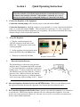
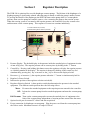
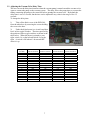
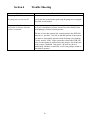
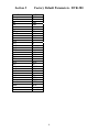
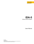
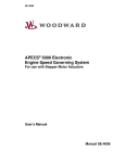
Temperature Control for Research and Industry Digital Vacuum Regulator User’s Manual Model DVR-380 INDEX PAGE SECTION SAFETY NOTICES . . . . . . . . . . . . . . . . . . . . . . . . . . . . . . . . . . . . . . . . . . . . . . . . . 3 1. QUICK OPERATING INSTRUCTIONS . . . . . . . . . . . . . . . . . . . . . . . . . . . . . 4 2. REGULATOR DESCRIPTION . . . . . . . . . . . . . . . . . . . . . . . . . . . . . . . . . . . . . 5 3. OPERATIONS GUIDE . . . . . . . . . . . . . . . . . . . . . . . . . . . . . . . . . . . . . . . . . . . . 6 3.1 How the Controller Adjusts Pressure . . . . . . . . . . . . . . . . . . . . . . . . . . . . . 6 3.2 Adjusting the Vacuum Valve Delay Time . . . . . . . . . . . . . . . . . . . . . . . . . 7 3.3 Adjusting the Amount of Hysteresis . . . . . . . . . . . . . . . . . . . . . . . . . . . . . 8 3.4 Changing the Display Resolution . . . . . . . . . . . . . . . . . . . . . . . . . . . . . . . 8 3.5 Correcting Offset in the Displayed Pressure . . . . . . . . . . . . . . . . . . . . . . . 9 4. TROUBLE SHOOTING . . . . . . . . . . . . . . . . . . . . . . . . . . . . . . . . . . . . . . . . . .10 5. FACTORY DEFAULT PARAMETERS . . . . . . . . . . . . . . . . . . . . . . . . . . . . . 11 Warranty J-KEM Scientific, Inc. warrants this unit to be free of defects in materials and workmanship and to give satisfactory service for a period of 6 months from date of purchase. If the unit should malfunction, it must be returned to the factory for evaluation. If the unit is found to be defective upon examination by J-KEM, it will be repaired or replaced at no charge. However, this WARRANTY is VOID if the unit shows evidence of having been tampered with or shows evidence of being damaged as a result of excessive vibration, corrosive materials, or misuse. Components which wear or are damaged by misuse are not warranted. This includes valves and fuses. THERE ARE NO WARRANTIES EXCEPT AS STATED HEREIN. THERE ARE NO OTHER WARRANTIES, EXPRESSED OR IMPLIED, INCLUDING BUT NOT LIMITED TO THE IMPLIED WARRANTIES OF MERCHANTABILITY AND OF FITNESS FOR A PARTICULAR PURPOSE. IN NO EVENT SHALL J-KEM SCIENTIFIC, INC. BE LIABLE FOR CONSEQUENTIAL, INCIDENTAL OR SPECIAL DAMAGES. THE BUYER'S SOLE REMEDY FOR ANY BREACH OF THIS AGREEMENT BY J-KEM SCIENTIFIC, INC. OR ANY BREACH OF ANY WARRANTY BY J-KEM SCIENTIFIC, INC. SHALL NOT EXCEED THE PURCHASE PRICE PAID BY THE PURCHASER TO J-KEM SCIENTIFIC, INC. FOR THE UNIT OR UNITS OF EQUIPMENT DIRECTLY AFFECTED BY SUCH BREACH. Returns, requests for service and inquires should be directed to: J-KEM Scientific, Inc. 6970 Olive Blvd. St. Louis, MO 63130 (314) 863-5536 Fax: (314) 863-6070 Internet Catalog: http:\\www.jkem.com E-mail: [email protected] 2 Safety Notices Solvents and Vapors J-KEM’s Model DVR 380 vacuum regulator should not be used in an environment containing flammable organic or gas vapors. It is recommended that the DVR 380 be used outside of research hoods away from vapors. CAUTION: Only qualified personnel knowledgeable in laboratory procedures should use this equipment.. Symbols Power Switch: 1 - Mains power (220-240vac) is ON 0 - Mains power (220-240vac) is OFF Caution. Risk of electric shock. ! Caution. No user serviceable parts Protective conductor terminal. Earth Ground. General Notice WARNING: If equipment is not used as specified in this manual, the protection provided by this equipment may be impaired. Stability The Model 380 is equipped with a side-mounting clamp. The controller should not be clamped to a free standing ring stand that can tip over. The Model 380 should only be clamped to lattice networks securely attached to a bench or laboratory hood. Power Voltage: Wattage: Fusing: 220-240 VAC @ 50-60Hz 2400 watts; 10 amps. 10 amp fast acting (F) 240 vac. Environmental Indoor use Altitude up to 2000 meters Operating temperatures of 5o C to 40o C Maximum relative humidity of 80% for temperature up to 31o C decreasing linearly to 50% relative humidity at 40o C. Installation category II 3 Section 1 Quick Operating Instructions NOTICE: When making a connection to the vacuum inlet or outlet fitting on the back of the controller, it is critically important that the vacuum tube does not rotate or damage to the controller will result. When making a connection, use a pair of pliers to prevent the tube from rotating while making any connection to the tubing. 1. Connect the Regulator to the Equipment Connect the vacuum pump (or the vacuum source) to the tube marked “Inlet”. Connect the instrument in which the vacuum is to be regulated (i.e., rotary evaporator, distillation setup, etc.) to the tube marked “Outlet”. There should be no restrictions (i.e. valves, stopcocks) between the Outlet port and the equipment you’re regulating. Best results are obtained when large diameter tubing is used to make this connection. 2. Set up the Regulator 1. Plug the vacuum pump into the 240VAC receptacle on the back of the DVR-380. Turn the power switch to the vacuum pump On. 2. Set the regulator selection switch on the front of the DVR-380 to the Off position. 3. Turn power to the DVR-380 On. 3. Regulator Selection Switch Enter the Setpoint Pressure. The default display of the meter is the pressure inside the piece of equipment the DVR is attached to. The desired pressure (or setpoint) is entered by holding in the “*” button on the front of the meter and simultaneously pressing either the ↓ button to decrease or the ↑ button to increase the setpoint. The setpoint, which appears as a blinking number, can be seen at any time by holding in the “*” button. 4. Move the Regulator Selection Switch to the METER Position. When set to the Meter position, the regulator maintains the attached equipment at the setpoint pressure entered in step 3. 5. For Controllers Equipped with Needle Valves, open the valve until the equipment is evacuated at a reasonable rate. When at the setpoint, adjust the valve for stable pressure regulation. Leave the needle valve in this position for future use. Once the valve is set for a reasonable evacuation rate it doesn’t require further adjustment. 4 Section 2 Regulator Description The DVR-380 is optimized for use with diaphragm vacuum pumps. The lifetime of the diaphragm of a diaphragm pump is significantly reduced when the pump is turned on while the pump is under vacuum. To prolong the lifetime of the diaphragm, the DVR-380 turns on the pump while it’s at atmospheric pressure, then once the pump has started it opens a valve connecting the pump to the reaction system. When the reaction system is evacuated to the setpoint pressure, the controller closes the vacuum valve and then turns off the vacuum pump. This sequence of events can continue indefinitely. 7- Serial Comm Port (on back) 8-Vacuum Pump Power Outlet (on back) 4 6 1 2 5 3 1. 2. 3. 4. 5. 6. Pressure Display. The default display is the pressure inside the attached piece of equipment in units of mm of Hg (torr). The setpoint pressure can be seen any time by holding in the “*” button. Control Key. Pressing (and holding) this button causes the regulator to display the setpoint pressure as a blinking number in the display. The setpoint is changed by holding in the control key and simultaneously pressing the ↑ key to increase or the ↓ key to decrease the displayed value. Decreases (↓) or increases (↑) the setpoint pressure when the “*” button is simultaneously held in. Regulator’s Power Switch. Indicates the position of the regulator selection switch (#6). Regulator Selection Switch. A three position switch that determines the pressure in the attached equipment. The different switch positions have the following effects: Meter: Off: 7. 8. Evacuates the attached equipment to the setpoint pressure entered in the controller. Isolates the vacuum pump from the attached equipment and turns the vacuum pump off. Full Vacuum: Turns on the vacuum pump and evacuates the attached piece of equipment to the limit of the vacuum pump, independent of setpoint pressure entered into the meter. Optional serial port for remote PC control and data acquisition. Power connection for diaphragm vacuum pump. Plug the power cord from the vacuum pump into the 240vac outlet. Maximum current is 10 amps @ 240vac. 5 Section 3 Operations Guide 3.1 How the Controller Adjusts Pressure For the controller to regulate pressure, enter a setpoint into the meter, for example 200mmHg, and set the regulation selection switch to the Meter position. If the setpoint pressure is below the current pressure the controller turns the vacuum pump on and then pauses for a user set period of time to allow the pump to generate a vacuum. After this delay, the controller opens a vacuum valve that normally isolates the vacuum pump from the reaction setup. The delay time between starting the pump and opening the vacuum valve can be set by the user (see below), the default value is 2 seconds. The system continues to evacuate until the system pressure equals the setpoint pressure. At this point, the controller closes the vacuum valve, isolating the system, and turns off the vacuum pump. Vacuum pump turns on Vacuum valve opens Vacuum Vacuum Profile Pressure offset (hysteresis) Point 2 202mm Hg 200mm Hg Point 1 Setpoint Time To prolong the life of the pump, it’s desirable to limit how frequently it’s turned on and off to adjust the system pressure. This is done by entering an allowable pressure band for the system as opposed to a discrete pressure point. The wider the allowable band, the less frequently the pump is turned on, but in most applications it’s desirable to limit the pressure band to a fairly narrow range. The pressure band is know as hysteresis, and the user can program the amount of hysteresis the controller allows (see below). By default, the DVR-380 is set for 2mmHg of hysteresis. Hysteresis always tracks the setpoint. For example if hysteresis is set for 2mmHg then when a setpoint of 200mmHg is set, the upper limit of the pressure band is automatically set to 202mmHg. If the setpoint is changed to 50mmHg, then the upper limit of the pressure band is automatically set to 52mmHg. Every time the setpoint is changed the upper limit of the band is automatically set to the pressure which is the amount of hysteresis above the new setpoint. 6 3.2 Adjusting the Vacuum Valve Delay Time The user can set the delay time between when the vacuum pump is turned on and the vacuum valve opens to connect the pump to the vacuum system. The delay allows the pump time to evacuate the tubing connecting the pump to the controller before opening the vacuum valve. By default the delay time is set to 2 seconds, but the time can be adjusted to any value in the range of 0 to 15 seconds. To change the delay time: 1) Take off the black cover of the DVR-380 from the white base by removing the screws holding the cover to the base. 2) Under the digital meter is a circuit board that has 4 in-line toggle switches. The time specified by the position of these toggle switches as shown in the table below. When the meter is pointed to your right, switch 1 is on the left and switch 4 is on the right. A switch is ON when it’s down and OFF when it’s up. Delay Time (seconds) 0 1 2 3 4 5 6 7 8 9 10 11 12 13 14 15 Switch 1 Position ON OFF ON OFF ON OFF ON OFF ON OFF ON OFF ON OFF ON OFF Switch 2 Position ON ON OFF OFF ON ON OFF OFF ON ON OFF OFF ON ON OFF OFF 7 Switch 3 Position ON ON ON ON OFF OFF OFF OFF ON ON ON ON OFF OFF OFF OFF Switch 4 Position ON ON ON ON ON ON ON ON OFF OFF OFF OFF OFF OFF OFF OFF 3.3 Adjusting the Amount of Hysteresis Whenever a setpoint pressure is entered by the user, a pressure offset that is 2mm Hg (factory default) above the setpoint is automatically entered into the meter. The purpose of the offset is to limit how often the vacuum pump is turned On and Off to maintain system pressure. The amount of offset, or hysteresis, can be set by the user by following the procedure below. The allowable range for hysteresis is 0.0 to 760mmHg. 1 2 3 4 Press and hold in both the and keys on the front of the digital meter until the word “tunE” appears in the display, then release both keys. Press the key once and the word “bAnd” will appear in the display. Next, hold in the ‘*’ key, then while holding in the ‘*’ key press the or keys until the amount of desired hysteresis appears in the display. For example, if you want 10mm of hysteresis, hold the or keys until 10 shows in the display. Let go of all the keys. Press the key 5 times until the word “oFSt” appears in the display. Next, hold in the ‘*’ key, then while holding in the ‘*’ key press the or keys until the amount of desired hysteresis appears in the display. For example, if you want 10mm of hysteresis, hold the or keys until 10 shows in the display. Let go of all the keys. NOTE: The value entered in Step 3 must be the same value that was entered in Step 2. Press and hold in both the and keys until the system pressure appears in the display, then release both keys. 3.4 Changing the Display Resolution. The procedure below allows you to select the pressure display resolution of your J-KEM vacuum controller. This procedure allows you to specify 0.1 or 1 torr resolution. 1. 2. 3. 4. 5. 6. Press and hold in both the and keys on the front of the digital meter until the word “tunE” appears in the display, then release both keys. Press the key until “LEVL” appears in the display. Next, hold in the ‘*’ key, then while holding in the ‘*’ key press the key until “3” appears in the display. Let go of all the keys. Press the key 11 times until “vEr” appears in the display. Next, hold in both the and keys for about 10 seconds until the display changes (what the display changes to can be variable, so just hold in the button until vEr goes away). Press the or key until “LoCk” appears in the display. While holding in the ‘*’ key, press the or key until ‘NonE’ appears in the display. Let go of all the keys. Press the key until “LEVL” appears in the display. Next, hold in the ‘*’ key, then while holding in the ‘*’ key press the key until “2” appears in the display. Let go of all the keys. Press the key 7 times until “diSP” appears in the display. Next, hold in the ‘*’ key, then while holding in the ‘*’ key press the or keys until “1”, to select 1 torr resolution, or “0.1”, to select 0.1 torr resolution, appears in the display. Let go of all the keys. Press and hold in both the and keys until the temperature appears in the display, then release both keys. Temperature is now displayed in the selected units. 8 3.5 Correcting Offset in the Displayed Pressure. A small amount of error can develop in the displayed pressure (≈ 2 torr) of the vacuum regulator. This is due to the wide pressure range of the transducer used and accuracy better than this is usually not possible. For display errors greater than 2mm, the controller can be calibrated using the procedure below (For users experienced with J-KEM’s meter, do not correct pressure using the “ZEro” function. This introduces an error, not a correction). Before beginning this procedure you will need to know the correct barometric pressure inside your lab. This procedure should only be performed by a qualified electrician. 1. Remove the controller’s cover. 2. Plug the OUTLET port of the regulator and set the regulator selection switch to the FULL VACUUM position. 3. Let the controller warm up for 10 minutes. 4. Connect a vacuum pump to the INLET port, turn it on and let it evacuate the controller to as close to 0 torr as possible. Measure the pressure in the system using a manometer. The regulator must be evacuated to as close to 0 torr as possible before the adjustment in step 5 is performed. 5. Adjust the “Zero” pot until the reading on the meter matches the actual pressure. 6. Turn the vacuum pump off and unplug the OUTLET port. Adjust the “Span” pot until the meter reads the actual barometric pressure in the lab. 7. Turn the controller off and replace the cover. 9 Section 4 Trouble Shooting Symptom The pump does not start Corrective Action The pump does not start at all Verify that the circuit breaker protecting the pump has not tripped. Reset the circuit breaker. The pump starts when the system is first turned on, but not when the system is evacuated Diaphragm pumps are designed to start when the diaphragm is at or close to atmospheric pressure, but will not start reliably when the diaphragm is under vacuum pressure. The line or hose that connects the vacuum pump to the DVR-380 must have a “pin-hole” size leak so that this portion of the system can return to atmospheric pressure when the pump is not running. Usually, normal “leaks” in the system that connect the DVR-380 to the vacuum pump are sufficient for this purpose, but if this part of the system is plumbed “leak-proof”, the user may have to intentionally introduce a small leak to allow the pump to return to atmospheric pressure. 10 Section 5 Parameter Tune Band Int Der DAC Cycle time Offset SP.LK Sprr Sprn Soak Set2 Bnd2 Cyc2 SP1P hand PL1 PL2 SP2A SP2b disp hi.sp lo.sp inpt unit sp1.d sp2.d burn Reu.d Reu.l span Lock Factory Default Parameters. DVR-380 Value Off 2 Off Off 1.5 On/Off 2.0 Off 0 Off -0 2 On/Off off 100 100 none none 0.1 800.0 0.0 Lin3 set Rly SSd Up.Sc 1d.2d 1i.2i 0 Level 2 11