1
TELETASK
Home Automation Systems
Technical Handbook
Systems features and software training book
Version: September 1th, 2010
PROSOFT Suite 3.2
TELETASK Handbook
Content >
Table of content
Table of content ................................................................................ 3 Introduction ....................................................................................... 8 1. The TELETASK domotics system .............................................................. 8 2. Hardware and Software ............................................................................ 10 2.1. PROSOFT Suite ....................................................................................................... 10 2.1.1. Introduction ....................................................................................................................... 10 PROSOFT ....................................................................................... 12 3. Introduction ............................................................................................... 12 3.1. The basic flow diagram of a configuration session ................................................... 12 3.2. The full flow diagram ................................................................................................. 14 4. Starting up a new project .......................................................................... 15 4.1. Collecting the project information ............................................................................. 15 4.1.1. The TELETASK central unit ............................................................................................. 15 4.1.2. The list of rooms ............................................................................................................... 15 4.1.3. The list of outputs ............................................................................................................. 15 4.1.4. The list of inputs................................................................................................................ 16 4.1.5. Information about the electrical contractor or system integrator. ..................................... 16 4.1.6. Information about the owner of the house ........................................................................ 16 4.2. Starting a project ....................................................................................................... 16 4.2.1. Installing PROSOFT on a PC ........................................................................................... 16 4.2.2. Starting PROSOFT the first time ...................................................................................... 16 4.2.3. Select the central unit which will be used in your project ................................................. 17 4.2.4. Saving project option on the PC ....................................................................................... 17 4.2.5. Project options (menu 'extra') ........................................................................................... 17 5. The rooms ................................................................................................. 23 5.1. Introduction ............................................................................................................... 23 5.2. Overview of the rooms .............................................................................................. 23 5.3. Adding rooms to the list of rooms ............................................................................. 24 6. 'O' Units: Outputs ...................................................................................... 25 6.1. General notes ........................................................................................................... 25 6.1.1. Output ............................................................................................................................... 25 6.1.2. Output unit ........................................................................................................................ 25 6.1.3. Output numbers ................................................................................................................ 25 6.1.4. 'O' Address (Output Address) ........................................................................................... 26 6.2. Adding Output units .................................................................................................. 26 6.2.1. The different available parameters ................................................................................... 26 6.2.2. In practice ......................................................................................................................... 27 6.3. Assigning TELETASK Outputs. ................................................................................ 28 6.3.1. The different available parameters: .................................................................................. 28 6.3.2. In practice: ........................................................................................................................ 29 6.4. Overview of the available TELETASK Output units and their parameters ................ 29 6.5. List of output units of your project. ............................................................................ 30 6.5.1. Generating Lists on the screen of your PC ...................................................................... 30 7. 'I' units: Inputs and other ........................................................................... 34 7.1. General notions ........................................................................................................ 34 7.1.1. 'I' interfaces: Inputs and other........................................................................................... 34 7.1.2. 'I' Address: ........................................................................................................................ 34 7.2. Adding TELETASK 'I' interfaces ............................................................................... 35 7.2.1. Parameters for adding new 'I' interfaces: ......................................................................... 35 7.2.2. In practice: ........................................................................................................................ 36 7.3. Configuring the parameters of 'I' Interfaces. ............................................................. 37 3
TELETASK Handbook
Content >
7.3.1. General 'I' interfaces ......................................................................................................... 37 7.3.2. Digital Input interfaces. ..................................................................................................... 41 7.3.3. Sensor Heat/Cool interface .............................................................................................. 42 7.3.4. Audio Interfaces ................................................................................................................ 47 7.3.5. Overview list of 'I' Interfaces of your domotics project...................................................... 48 7.4. TDS12022 AURUS-OLED ........................................................................................ 52 7.4.1. Add an AURUS-OLED ...................................................................................................... 52 7.4.2. Overview ........................................................................................................................... 53 7.4.3. Interface data (horizontal/vertical) .................................................................................... 54 7.4.4. Built-in temperature sensor. ............................................................................................. 54 7.4.5. Pages................................................................................................................................ 55 7.4.6. Buttons.............................................................................................................................. 56 7.4.7. Edit this screen-menu ....................................................................................................... 57 7.4.8. Displaying the Sensor and Audio zones........................................................................... 60 7.4.9. Delete the AURUS-OLED memory & demand the version number. ................................ 61 8. Functions .................................................................................................. 62 8.1. Overview of the different functions ........................................................................... 62 8.1.1. The Relay functions .......................................................................................................... 62 8.1.2. The Dimmer functions ...................................................................................................... 64 8.1.3. The Motor functions .......................................................................................................... 66 8.1.4. The Motor functions. ......................................................................................................... 68 8.1.5. The Timer functions .......................................................................................................... 70 8.1.6. The Sensor Functions ...................................................................................................... 72 8.1.7. The Fan function ............................................................................................................... 75 8.1.8. The Local Mood function .................................................................................................. 77 8.1.9. The Timed Local Mood function ....................................................................................... 79 8.1.10. The General Mood function ............................................................................................ 81 8.1.11. The Transparent function ............................................................................................... 83 8.1.12. The Messages and Alarms functions ............................................................................. 84 8.1.13. The TP Buzzer functions ................................................................................................ 88 8.1.14. The 'If-Then-Else' function .............................................................................................. 90 8.1.15. The Process functions .................................................................................................... 92 8.1.16. The 'Flag' function .......................................................................................................... 95 8.1.17. The Condition ................................................................................................................. 96 8.1.18. The Service functions ..................................................................................................... 98 8.1.19. The clock functions ....................................................................................................... 100 8.1.20. The audio functions ...................................................................................................... 102 8.1.21. Send IR/RS232 Code ................................................................................................... 103 8.1.22. The Auto start function ................................................................................................. 105 8.1.23. The Display Functions .................................................................................................. 106 8.1.24. The step function .......................................................................................................... 108 8.1.25. The RGB function. ........................................................................................................ 109 9. Communication ....................................................................................... 111 9.1. Connecting your PC with the central unit ................................................................ 111 9.1.2. USB Communication ...................................................................................................... 112 9.1.3. Ethernet Communication ................................................................................................ 118 9.2. Connection trouble shooting ................................................................................... 125 9.2.1. In practice ....................................................................................................................... 125 9.2.2. Remark ........................................................................................................................... 125 9.3. Communication with the DOIP central unit ............................................................. 126 9.3.1. Send ............................................................................................................................... 126 9.3.2. Receive ........................................................................................................................... 127 10. Overview of your domotic project ......................................................... 128 10.1. Print your project ................................................................................................... 128 10.2. Hierarchic List ....................................................................................................... 128 TIMESOFT .................................................................................... 130 11. Actions based on time programs .......................................................... 130 11.1. Introduction ........................................................................................................... 130 4
TELETASK Handbook
Content >
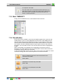
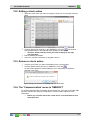
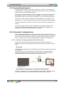
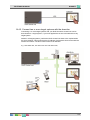
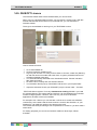
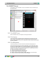
11.2. The different clock tables. ..................................................................................... 130 11.3. Start TIMESOFT. .................................................................................................. 131 11.4. Visualisation .......................................................................................................... 131 12. Defining a clock action .......................................................................... 133 12.1. Adding a new clock action .................................................................................... 133 12.1.1. Add a clock action ........................................................................................................ 133 12.1.2. The different available parameters ............................................................................... 133 12.2. Editing a clock action ............................................................................................ 134 12.3. Remove a clock action .......................................................................................... 134 12.4. The 'Communication' menu in TIMESOFT ........................................................... 134 CARDSOFT .................................................................................. 135 13. Access Control ...................................................................................... 135 13.1. Introduction ........................................................................................................... 135 13.2. Starting CARDSOFT ............................................................................................. 135 13.3. Configuring an intelligent card or tag .................................................................... 136 13.3.1. Adding an intelligent card or tag ................................................................................... 136 13.3.2. Editing an intelligent card or tag ................................................................................... 137 13.3.3. Remove an intelligent card/tag. .................................................................................... 137 13.4. The Communication menu in CARDSOFT ........................................................... 137 GUISOFT ...................................................................................... 138 14. Personalised graphical control .............................................................. 138 14.1. Introduction ........................................................................................................... 138 14.1.1. Graphical User Interface (GUI) ..................................................................................... 138 14.2. Glossary ................................................................................................................ 138 14.2.1. GUISOFT ...................................................................................................................... 138 14.2.2. iSGUI/GUI(+) ................................................................................................................ 138 14.2.3. GUI Runtime (GUI/GUI+) ............................................................................................. 138 14.2.4. iGUI/SmartGUI (= iSGUI) ............................................................................................. 138 14.2.5. Target Device ............................................................................................................... 138 14.3. System Requirements .......................................................................................... 139 14.4. Schematic Configurations ..................................................................................... 139 14.4.1. Connect one target system with the domotics .............................................................. 139 14.4.2. Connect two or more target systems with the domotics. .............................................. 140 14.5. GUISOFT Licence ................................................................................................ 141 15. Making a GUI/GUI+ .............................................................................. 142 15.1. Requirements Session workflow ........................................................................... 142 15.2. CREATING A GUI/GUI+ ....................................................................................... 144 15.3. GUI Selection ........................................................................................................ 144 15.4. GUI Properties ...................................................................................................... 145 15.5. GUISOFT Screen ................................................................................................. 146 15.5.1. The GUISOFT menu .................................................................................................... 147 15.5.2. The functions and symbols library ................................................................................ 147 15.5.3. The GUI Preview .......................................................................................................... 147 15.6. Adding items to the GUI ........................................................................................ 148 15.6.1. Drag and drop ............................................................................................................... 148 15.6.2. Positioning (grid) ........................................................................................................... 148 15.6.3. Edit the GUI Icon .......................................................................................................... 148 16. Creating a iSGUI ................................................................................... 152 16.1. Start with the GUISOFT ........................................................................................ 152 16.2. GUI Selection ........................................................................................................ 152 16.3. iSGUI Features ..................................................................................................... 153 16.4. GUISOFT Screen ................................................................................................. 154 16.4.1. The GUISOFT menu .................................................................................................... 154 16.4.2. The Functions ............................................................................................................... 154 16.4.3. The iSGUI preview ....................................................................................................... 154 5
TELETASK Handbook
Content >
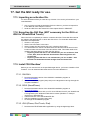
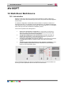
16.5. Adding items to the iSGUI. ................................................................................... 155 16.5.1. Drag and drop. .............................................................................................................. 155 17. Get the GUI ready for use. .................................................................... 156 17.1. Importing an activation file. ................................................................................... 156 17.2. Exporting the GUI files (NOT necessary for the GUI+ or iGUI for iPhone/iPod
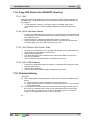
Touch) ............................................................................................................................ 156 17.3. Install 'GUI Runtime' ............................................................................................. 156 17.3.1. GUI/GUI+ ...................................................................................................................... 156 17.3.2. SGUI (SmartPhone) ..................................................................................................... 156 17.3.3. iGUI (iPhone, iPod Touch, iPad) .................................................................................. 156 17.4. Copy GUI Files to the GUISOFT directory ............................................................ 157 17.4.1. GUI ............................................................................................................................... 157 17.4.2. SGUI (Windows Mobile) ............................................................................................... 157 17.4.3. iGUI (iPhone, iPod Touch, iPad) .................................................................................. 157 17.4.4. GUI+ (MS Windows) ..................................................................................................... 157 17.5. Problem Solving .................................................................................................... 157 AV-SOFT ....................................................................................... 158 18. Multi-Room Multi-Source ...................................................................... 158 18.1. Introduction ........................................................................................................... 158 18.2. Multi-room/Multi-source: the differences ............................................................... 159 18.3. Phase 1: Choose the wanted audio/video configuration ....................................... 160 18.3.1. Define the requirements ............................................................................................... 160 18.4. Phase 2: Assigning the RS232 Port and the IR flashers. ..................................... 162 18.5. Phase 3: Configuring the Universal RS232 AV interface. ..................................... 164 18.5.1. Assigning IR codes or RS232 strings ........................................................................... 164 18.5.2. Entering the audio configuration in AV-SOFT .............................................................. 164 18.5.3. Assigning Sources. ....................................................................................................... 165 18.5.4. Assigning Zones: .......................................................................................................... 166 18.5.5. Configuring the RS232 universal AV interface. ............................................................ 166 18.6. Phase 4: Configuring the audio buttons of the domotics installation. ................... 169 19. Edit library ............................................................................................. 170 19.1. Add and edit devices into the library. .................................................................... 170 19.2. Entering RS232 strings ......................................................................................... 172 19.3. Record IR codes ................................................................................................... 173 19.4. Paste IR codes ..................................................................................................... 175 19.5. BACK-UP the AV-SOFT Library ........................................................................... 175 20. Connection to the RS232 UNIVERSAL AV INTERFACE ..................... 176 20.1. RS232 connection ................................................................................................ 177 20.2. Splitter Cable for audio system ............................................................................. 177 Multiple DoIP Central Units ........................................................... 178 21. Coupling of multiple Central Units. ....................................................... 178 22. PROSOFT SUITE ................................................................................. 178 22.1. PROSOFT ............................................................................................................ 178 22.1.1. Central Unit bounded.................................................................................................... 179 22.1.2. Interfaces ...................................................................................................................... 179 22.1.3. General moods ............................................................................................................. 179 22.1.4. Touch Panels ................................................................................................................ 179 22.2. TIMESOFT ............................................................................................................ 180 22.3. CARDSOFT .......................................................................................................... 180 22.4. GUISOFT .............................................................................................................. 180 22.5. AV-SOFT .............................................................................................................. 180 22.6. Communication ..................................................................................................... 180 Application Examples .................................................................... 181 23. Real examples ...................................................................................... 181 6
TELETASK Handbook
Content >
23.1. Introduction ........................................................................................................... 181 23.2. How to integrate a heating/cooling system ........................................................... 181 23.2.1. De basic operation of a heating/cooling control ........................................................... 181 23.2.2. The available internal temperature control algorithms ................................................. 182 23.2.3. Setting up the output control of the heating/cooling system......................................... 183 23.3. How to integrate a light sensor ............................................................................. 185 23.3.1. How to add a light sensor to your project ..................................................................... 185 23.3.2. The argument 'Hysteresis' ............................................................................................ 186 23.3.3. The TELETASK Lux-values table ................................................................................. 187 23.3.4. The meaning of a Lux value; practical approach.......................................................... 188 23.4. How to setup an access control system................................................................ 189 23.4.1. Description of the case study example ......................................................................... 189 23.4.2. Needed products: ......................................................................................................... 189 23.4.3. In practice ..................................................................................................................... 189 23.5. Configuring a NUVO installation with three RS232 interfaces. ............................. 192 23.5.1. Phase 1: Define the desired audio/video configuration: ............................................... 192 23.5.2. Phase 2: Assigning the RS232 Port (s). ....................................................................... 192 23.5.3. Phase 3: Configuring the RS232 universal AV interface.............................................. 193 7
TELETASK Handbook
Introduction >
TDS
Introduction
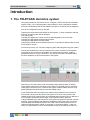
1. The TELETASK domotics system
This guide provides an overview of how to configure a TELETASK Home Automation
System (TDS). It is a complete guide to the PROSOFT -Suite configuration software
and other TELETASK products with additions and tips for a state-of-the-art integration.
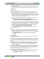
Prior to the configuration part you will find:
Capturing the requirements and wishes of the end-user, in close cooperation with the
end-user, architect and/or interior designer.
The Lighting plan
Choosing the appliances, motors, etc which will integrated by the to the TDS.
Choosing the appropriate heating/cooling system.
Choosing the appropriate security system.
Capturing the typical routes throughout the house, to be able tot decide where to place
touch panels or screen.
Once all this is done, you can start configuring (also called 'programming') the system.
Comfort and flexibility are not only important for the user, but also for the integrator.
The simplicity and comfort for the installer of a TELETASK automation system is
possible thanks to its unique construction. The specific structure is characterized by
the strict separation of inputs and outputs in the system.
With this way of working there is still something missing because there is nothing
which defines yet that the push button on the wall is for example going to control the
ceiling light in the dining room. Therefore the system needs a relation which is to be
defined between that particular input and the related output.
In the TELETASK domotics systems this relation will be defined in the central unit.
This central unit becomes the heart of the system and is a far more powerful and
reliable solution than working with a dé-centralised approach which has by definition a
more complex configuration and a larger chance that information gets lost.
In large installations you will learn that a multi-central unit approach will offer you both
simpicity, highest reliability and distributed intelligence without the need of a masterslave setup like dé-centralised systems use. With a TELETASK system there is no
central unit behaving like a master, so there are no such slaves eather. I case of a
failure, this guarantees no loss of functionalities except for the defect part itself. In a
8
TELETASK Handbook
Introduction >
TDS
dé-centralised setup where a master can fail, the whole system may go down or at
least lose a number of features which affect also non-defective parts of the system.
When using a TELETASK central unit (with power supply), there is only one main
component which is to be taken care of. All inputs and outputs can communicate with
this central unit and can be considered connected to it, although this may not be with a
whole bunch of wires and cable but only via a small high-speed data cable which we
call the 'AUTOBUS' cable.
This way all input-to-output relations become both simple and flexible, because they
are not defined as in a traditional solution, but by the powerful and flexible TELETASK
software relations. These relations are configures in the TELETASK PROSOFT-Suite.
PROSOFT is offered free with any TELETASK system and can be downloaded from
the website.
As a result of this, when for example pushing a wall mounted momentary push-button
(= the input), the ceiling light in the dining room (= the output), can be switched (= the
relation between the input and the output) on/off.
The relations can be defined by yourself, by means of PROSOFT software.
PROSOFT was specially developed by TELETASK to make it possible that you can
define all inputs, outputs and the relations between them on a standard MS Windows
based PC. As soon as your relations are defined, they can be downloaded to the
TELETASK central unit which will keep them in his non volatile memory, where they
always remain after disconnecting the PC, even when power fails for short or long
(unlimited) periods.
As soon as the relations are downloaded in to the central unit, the PC can be
disconnected from the central unit and is no longer needed. You will than be able to
control all integrated (= connected) lights, curtains, shutters, heating, cooling, audio,
etc… as defined. You can control all these outputs by means of standard buttons and
specific touch panels, sensors, touch screens or even by remote control, by mobile
phone or on a PC, PDA/Webpad via Ethernet over LAN/WAN wired- or wireless
connections.
9
TELETASK Handbook
Introduction >
Software
2. Hardware and Software
You will have noticed that there are both hardware and software items to be
distinguished.
The hardware part contains the different TELETASK components and the connection
to the central unit(s). All hardware components have their own specific features and
may behave as an input, an output or sometimes even both of them. To find out more
details about the hardware and its hardware aspects, please refer to the TELETASK
''datasheets'.
The software part contains the creation of the relations between the inputs and
outputs, defining extra functions, setting up integrations like heating/cooling, audio,
setting clocks, defining access control, etc…
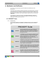
2.1. PROSOFT Suite
2.1.1. Introduction
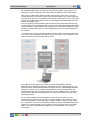
With PROSOFT SUITE you can define all integrations within your Home automation
project. If you install and run PROSOFT, you will see it consists out of 5 different
parts:
PROSOFT Suite
PROSOFT
This is the main and the most important software part. All
relations between inputs and outputs are defined in
PROSOFT. The file which is generated by PROSOFT is
also the basic file which is used in the other software
packages from below.
TIMESOFT
In TIMESOFT you have an electronic calendar in which
you can enter actions (for example switching a light or
change the temperature at a certain time of the day)
based on the internal clock of the central unit.
Click the TIMESOFT icon to to open the calendar and
configure the desired clock actions.
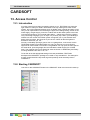
CARDSOFT
CARDSOFT is another part of te PROSOFT-Suite which
is used to enter and edit the Chip cards- and Tags which
are to be used at the integrated access control interfaces
from TELETASK. Click the CARDSOFT icon to define the
cards or tags for the actual project.
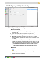
GUISOFT
GUISOFT is used to generate one or more GUI’s (both for
standard- PC and/or smaller mobile devices). With these
GUI's you are able to control the TELETASK domotics
system based on floor plans or menu's depending on the
device you are using).
AV-SOFT
AV-SOFT is used to enter all needed parameters for the
integration of any audio, video or home theatre system
using the universal RS232 interface TDS14042. In AV-soft
you can use existing protocols or add a custom protocol.
10
TELETASK Handbook
Introduction >
Software
Beside of the PROSOFT -Suite there is also IR-SOFT as a seperated software. IRSOFT is only needed for changes on older projects where the TDS14042 IRLearnable Interface or the TDS14045 Xantech Interface has been used.
IR-SOFT
IR-SOFT is used to enter all needed parameters for the
special audio integration interfaces TDS14041 (general
learnable IR-generator) and TDS14045 (XANTECH audio
interface)
For newer projects the TDS14042 RS232/IR larnable Interface is used in a
combination with AV-SOFT, a fixed part of the PROSOFT Suite.
For older installations (before V3.0):
PROSOFT Suite makes the file management for every project easier because all
project data is stored in one file. The PROSOFT Suite '.nbt' contains all data that
previously (existing installations) was stored previously in three different files
('.nbt', '.clk' and '.crt' files). The file generated by IR-SOFT (if used) stays a
separate file.
PROSOFT Suite is able to read with ease all your old '.nbt' files starting from
PROSOFT V2.75. Files made in versions before PROSOFT V2.75 can be easily
converted by opening them in PROSOFT V2.75 and save it with a new name in
that software version. Save the .nbt file in this software version with a new name.
Remarks: For this conversion you don't need upgrades (no new EEPROM chips).
Your old TIMESOFT ('.clk') and CARDSOFT ('.crt') files can be imported in the
TIMESOFT and CARDSOFT mode of PROSOFT Suite by clicking respectively
'File> Import clocks (old .clk)' or 'File'>Import cards (old .crt)'.
In this technical handbook you will find all software aspects of your TELETASK
domotics system treated in detail. Because the hardware and the software items are
connected close to each other, we will regularly refer to the DATA SHEETS handbook
where you can find any specific datasheet you may need.
You can always download the latest version of most of the documents from the
TELETASK website www.teletask.be. If you are using the latest version of the
PROSOFT-Suite, you can also open this Technical handbook and the datasheets
handbook via the Help menu.
The PROSOFT Suite uses the .NET (read 'dotnet') surrounding. When
installing PROSOFT from the supplied (CD-ROM) it will be installed
when needed. More recent PC's contain .NET by default.
In exceptional cases it can be necessary to install this ".NET"
separately. That's when the PC doesn't contain it and when PROSOFT
was downloaded from the TELETASK website.
11
TELETASK Handbook
PROSOFT >
Introduction
PROSOFT
3. Introduction
PROSOFT is the main software package to configure a TELETASK domotics
installation. At the end In PROSOFT you will define all the relations between all earlier
defined outputs and inputs of your system.
So Before you can start making relations, you must enter the hardware configuration
of your installation. All used parts will have to be entered and given some or more
extra parameters.
Although every TELETASK installation is different, there is some fixed road map to be
followed step by step. The different steps are covered in the headings below.
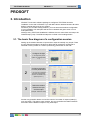
3.1. The basic flow diagram of a configuration session
Setting up the relation between an input and an output is basically very simple. There
are only about three steps to be done to define that for example a certain light is
switched on/off by means of a certain (momentary) push button on the wall:
1
2
3
Configure the light
(= an output relay of the
system. for example relay
nr. 1)
Configure the button
or touch panel button
(= an input as for example
the button in the kitchen
which is connected to the
system input nr. 1)
Define the relation
between the input
and the output
(example: 'SWITCH' on/off)
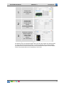
Another very powerful relation can be the control of a number of outputs (loads) by
only one button. This seems more complex, but you can define the relation between
the button and the different outputs in only three steps.
12
TELETASK Handbook
1
2
3
PROSOFT >
Introduction
Configure the
connected lights
(outputs)
Configure the
function which
contains all the
outputs
(ex: list of all outputs which
will have to be controlled at
once)
Define the necessary
relation between a
button and the
custom made
function
(ex. 'local mood')
All relations which are defined between the inputs and the outputs are always based
on one of the two flow diagrams above. It is the functionality of the chosen relation
(sometimes this can be more than one function) between the inputs and the outputs
which may increase the level of complexity of your work.
13
TELETASK Handbook
PROSOFT >
Introduction
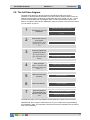
3.2. The full flow diagram
The basic flow diagram of above shows the simple basic task to be done in
PROSOFT: defining relations between inputs and outputs. Because there is also the
opening of the program, sending the configuration file to the central unit, etc… below
there is the extended basic flow diagram which contains all necessary steps to be
taken to complete a TELETASK / PROSOFT task from scratch to the end point where
you can switch off you PC.
1
Collect all project related information
The start-up of a new
installation
2
Enter all the rooms of
your project.
3
Enter all outputs and
give them a name
(example: kitchen, office,
garage, toilet 1, garden,
etc.)
5
6
7
Enter all rooms
Add all necessary output interfaces
(R1 = light in toilet nr.1)
(R2 = wall socket on the
terrace)
4
Open the new project (start PROSOFT on
your PC)
Enter all inputs.
Give a name to every single output
Add all necessary input interfaces
(Input 1 = "left button of the
double button panel in the
toilet nr. 1")
Enter the name of the input
Define all necessary
functions
Define the functions
Define the relations
Save and send the
generated file from
the PC to the central
unit
Enter the relations
Save your file on the PC (CD Rom)
Send from PC to central unit
The different steps in this flow diagram will be explained in detail in the text below.
IMPORTANT: Don't forget to make a back-up of your .nbt file which is generated by
the PROSOFT-Suite. It is important to keep this back-up file available over the full lifetime of the installation.
14
TELETASK Handbook
PROSOFT >
Start of a Project
4. Starting up a new project
4.1. Collecting the project information
Before starting up a new project, it is recommended to have all technical details of the
TELETASK hardware components which are needed in the project. This information is
to be given by the system integrator. The information is necessary to be able to use
PROSOFT in a simple and straightforward way. The information will also result in a
correct documentation print-out of the full custom project. Below there is an overview
of the information you need before you can proceed with the next step.
4.1.1. The TELETASK central unit
You will have to define which central unit is going to be used in the project. As this is
one of the first items which is decided, you should easily find out which central unit is
used for the project. Please refer to the data sheets of the available central units.
- The features and capacity of the NANOS and MICROS+central units are equal. Also
in configuration they are about the same.
- There is a mechnical differnce: The NANOS central unit is DIN-rail mounted and may
be more comfortable to use from a technical perspective, but MICROS+ is in most
cases slightly more price effective. But this also depends on the labour cost and the
available space in and around your electrical cabinet(s).
- When you need AUTOBUS 1 and 2 to be galvanically isolated from each other,
NANOS is to be used with at least 2 power supplies. The MICROS+ has no galvanis
isolation possible between AUTOBUS 1 and 2.
4.1.2. The list of rooms
The 'list of rooms' contains an overview of all rooms in your project. Not only indoor
rooms, but also outdoor areas will be needed to be divided in to 'rooms'. Rooms are
best to be obtained from the architectural drawings. The room names you use are
important as they are also to be well understood by the people living in the house. A
simple' bedroom' name will not be sufficient as name if there are more bedrooms in
the house. We recommend adding the name of the person for which the room is
planned to be occupied. For example 'bedroom parents' or 'bedroom Maria' is better
than 'bedroom 2'. Using familiar names is better for a good communication with the
occupants. It will save you time and it increases the quality of the solution you are
offering with TELETASK.
PROSOFT makes no distinction between indoor and outdoor rooms.
4.1.3. The list of outputs
The 'list of outputs' gives an overview of all TELETASK output interfaces (for example
relay interfaces), with an overview of which output interface and contact is connected
to which load. This list is based on the elctrical board informaion and is obtained from
the electrical contractor. This list may be, depending on the project, several pages
long and is absolutely needed before you can proceed. Please be sure that you have
all information as listed below, before you proceed.
Type of output: depending on the connected load and the desired control:
Relay: used to switch on/off (for example a switchable light)
Dimmer: used to dim (for example a dimmable light)
Motor: used to control AC or DC motors (for example: opening/closing a
curtain of shutter).
Type of output interface: f.e. TDS13500: 4OUTO8RB' AUTOBUS Relay
interface, TDS13524 for AC motors; TDS13525 for DC motors
Output number: for example Relay output nr. 1, or Dimmer nr. 10
Extra Information:
15
TELETASK Handbook
PROSOFT >
Start of a Project
Room: This is the room where the connected load is installed (for example
'living room'; to be chosen out of the 'rooms' list).
Icon: describes which kind of load is connected: here you have the choice out
of a list: light, device (wall socket or other ON/OFF loads), motor or mood.
Name: gives a more precise load description (for example work top, washing
table; reading light…)
More information about these items can be found in heading 'O-interfaces: outputs'.
4.1.4. The list of inputs
The list of inputs contains all TELETASK input interfaces and the names (with location
indication) of the connected inputs such as window contacts, sensors, pushbuttons
etc… Having this full list (from the electrical contactor) is necessary before you can
proceed. Following information has to be available:
Type of input: depending the kind of signal, this input must be connected to a
certain type of input of the TELETASK system (only one of the different types
below can apply):
General type of input: external (not in the MICROS+ central unit housing)
interface like for example a touch panel AURUS ref. TDS12021xx.
Digital type of input: this is an input for all kind of voltage free contacts. For
example coming from a standard momentary push button, a window contact,
a motion detector contact or similar.
Analogue type of input: this is an input for an analog signal like coming from
a TELETASK temperature sensor:
AV type: for the integration of external A/V systems
Type of input interface used: this is the TELETASK interface type to which the
concerning input signal is to be connected. For example TDS12125 (Cookie with
feedback),
Input number: for example digital input- or button number 1
Extra information: custom note; for example 'push button in the kitchen next to
the stove'.
4.1.5. Information about the electrical contractor or system integrator.
To complete the report print-out, you need the name and the address of the electrical
installer or system integrator.
Add this informaiton in PROSOFT menu 'Extra' - 'Options' - 'System Setup'
4.1.6. Information about the owner of the house
A project is always related to a house or building. Therefore you need to have the
owners name and address to be filled in the dedicated area in PROSOFT.
4.2. Starting a project
As soon a all project details are available, you can start configuring
your TDS (TELETASK Domotics System). This is by using the PROSOFT software.
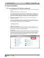
4.2.1. Installing PROSOFT on a PC
PROSOFT -Suite (V3.2 and higher) runs on Windows XP/Vista and Windows 7.
You can find the installation package of the PROSOFT Suite on the CD-ROM,
included with a DoIP Central unit or you can download it from www.teletask.eu from
the 'Downloads' menu.
Remark: You may have to 'register' first before you can start donwloading.
Confirmation of your access may take 24 hours before you may be able to login and
start downloading.
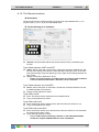
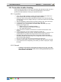
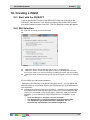
4.2.2. Starting PROSOFT the first time
16
TELETASK Handbook
PROSOFT >
Start of a Project
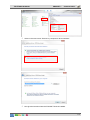
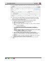
Click on the 'Start' button in the lower left corner on your screen.
Select 'Programs' in the start menu.
Select 'TELETASK' in the programs list.
Click on 'PROSOFT Vx.xx' in the TELETASK program list (x.xx stands for the
PROSOFT version).
PROSOFT starts now.
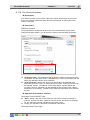
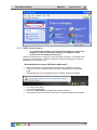
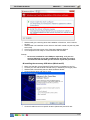
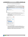
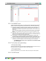
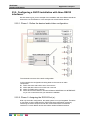
4.2.3. Select the central unit which will be used in your project
When PROSOFT has started, you will be asked if you want to start-up a new project
or an existing project for a specific central unit.
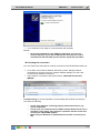
4.2.4. Saving project option on the PC
It is necessary to save the made .NBT file on you PC. Don't forget to save it when
working on it, not only when you have finished it. TELETASK suggests to add a new
file (version) number (example: MyProject V01.nbt) each time and increase this
number every time you've made essential changes. This way you can easily go back
to an older file version when the new version contains a mistake. It is also a handy tool
to make a difference between older and newer back-up versions of the file. You can
easily see which the old are and which the new files are.
Practical
Click on 'FILE' in the PROSOFT menu.
Click on 'SAVE' or 'SAVE AS' in the 'File' menu.
Give the project a name and add V01 (f.e. JAMES V01.NBT if you save this file
for the first time).
When you will save a new version, use regularly 'SAVE AS' and higher up the
version number V01 to V02, V03,…. (f.e. JAMES V02.NBT,…)
REMARKS
Make regular backups backups of your .NBT file, save them on your CD
ROM, DVD? USB-stick,.. and keep them safely for future use.
As soon as the project is finished, make a back-up of the latest version
and keep it safe (f.e. safe deposit box). The file can be very valuable
because of all the efforts which were made and possible private
information such as entrance code for the house, etc…
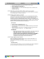
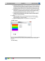
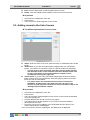
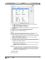
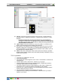
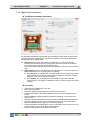
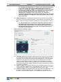
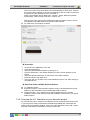
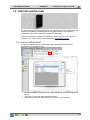
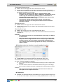
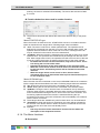
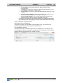
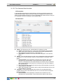
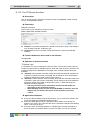
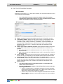
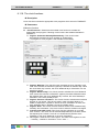
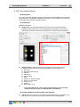
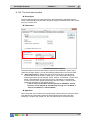
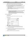
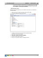
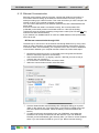
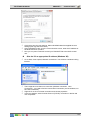
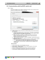
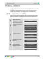
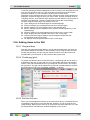
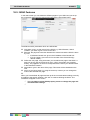
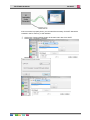
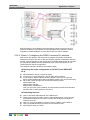
4.2.5. Project options (menu 'extra')
Click on 'OPTIONS' in the 'EXTRA' menu to fill in the project related details. The
Option window will appear on the screen.
In this window all the options are grouped in different tab pages. We will describe
them here:
System setup
In the tab window System Setup you can fill in the global project details: the details of
the electrical installer and the details of the owner of the house/project.
17
TELETASK Handbook
PROSOFT >
Start of a Project
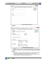
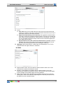
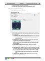
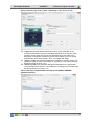
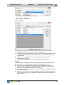
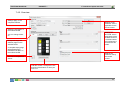
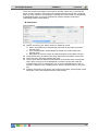
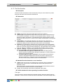
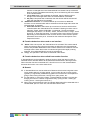
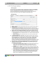
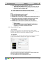
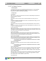
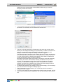
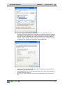
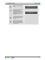
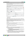
Option
'Language': here you can select the necessary language version you prefer for
PROSOFT Suite. You have to re-start the PROSOFT SUITE to activate changes.
This setting is no setting in the .NBT file but will be kept globally by the PROSOFT
Suite.
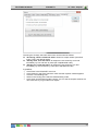
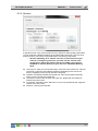
'Special':
Relay delay: here you can determine which time has to be elapsed between
the switching of a relay (this to avoid problems with inrush current).
Press Long bus interfaces: this determines how long you have to push on
a button before it will be recognized as 'Press Long'.
18
TELETASK Handbook
PROSOFT >
Start of a Project
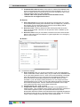
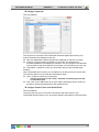
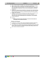
Feedback LED's blink on error: if this option is checked the feedback led's
of the touch panels will start to blink when the function behind is in 'error' (f.e.
when an output interface could not be found on the AUTOBUS). This is very
usefull during the start up of the installation.
Remark: older touch panels like the OCTO and PENTO series,
TDS12127 do not support this function.
Service:
Auto start function: this function will always be executed when the central
unit is started (after sending from PROSOFT, after a voltage loss,) Thanks to
this function you can assure that some 'critical' functions always will be
executed/started (e.g. process functions).
No Action timer: This time determines after which period the 'No-Action
alarm' will be executed. This timer can be put ON or OFF or RESET by the
service function.
No Action alarm: Here you can define a function which has to be executed
after the 'No-Action timer' has elapsed. A typical application is an emergency
alarm in service flats.
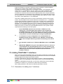
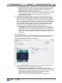
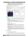
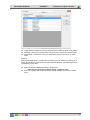
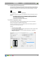
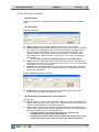
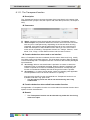
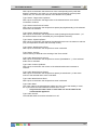
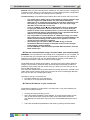
Sensor
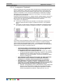
'Temperature settings':
Kind of heating: Here you can set up the heating cycle (only applicable for
sensor zones with control method 'relay', 'flag' or 'local mood'). Standard there
is no cycle and hysteresis of 0.5C° used. In this case the heating is activated
when the temperature is 0.5C° lower then the demanded temperature and
turned of when the demanded temperature is reached. When you have
activated a cycle, the heating will be periodical. On. How long there will be
heated depends on the chosen cycle and the difference between the desired
and measured temperature. Via this method the temperature can be kept
more optimal and the energy consumption will be lower.
'Kind of cooling: see': 'Kind of heating'
Temperature / 10V or 100% time: this parameter is only applicable for a
heating system: with multistage control, analog control and other methods of
control WITH regulated cycles. This parameter determines at which
temperature difference between the measured and the regulated temperature
the heating/cooling has to be controlled maximal. (high speed with multistage
control, 10V for analog control and 100% cycle for the others).
19
TELETASK Handbook
PROSOFT >
Start of a Project
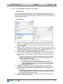
Activate the 'AUTO' modus: when this parameter is checked, the system will
automatically be able to switch from heating to cooling or reverse, depending
on the measured and regulated temperature. REMARK: if the 'AUTO' mode is
activated it is still possible to select the mode HEAT or COOL for every zone,
the system then will only heat or cool, it will never switch itself between them.
Delta Hot/Cool: when the measured temperature is higher then the regulated
temperature + this value then the system will go in AUTO modus and start
cooling. The regulated temperature for cooling for Day or Standby in a zone is
the regulated temperature for heating in this zone + this value.
Freeze protection temperature: the temperature which has to be obtained
minimally, even when the zone is "OFF"'OUT' or there is a window open in
this zone, to avoid frost damage.
'Others':
Hysteresis light sensor: the hysteresis which has to be used for a light
sensor. Because Lux values are a logarithmic scale this is not stipulated in
absolute values but in amount of steps.
Hysteresis humidity sensor: the hysteresis for a humidity sensor
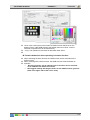
RGB settings
Here you can define maximum 10 basic colours for RGB functions as a kind of general
color pallet. These values can be used with the TDS12502 (remote control) via the
RGB button.
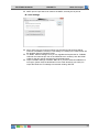
Time setting
20
TELETASK Handbook
PROSOFT >
Start of a Project
'Clock':
Time zone: here you can define the time zone which has to be used by the
central unit. This time zone also contains information about the use (or not) of
summertime and when this starts and ends.
Adapt time automatically (via the Internet): this regulation is advised when
you have a continuous connection with the internet. This way your central unit
clock will be synchronised with the 'Time Servers' on the internet. This results
in a very accurate clock which always will be correct in the whole project (all
touch panels and screens).
Synchronize de time of the central unit with the time of your PC: with this
regulation the clock of the central unit will be set even with the clock of your
PC when synchronising (each time when sending the .NBT file).
'Workday': Select all the days in a week which are 'Workdays' for you. This is
important when the regime will be on 'Automatic'.
E-MAIL
Report sender's name: this name will be used as sender's name of an e-mail
whenever the central unit will send an e-mail.
Sender's e-mail address: this address will be used as sender of an e-mail
whenever the central unit will send an e-mail. If the receiver of this e-mail replies
at this message, the message will be sent to this address.
SMTP Server (sent mails): the SMTP server address which has to be used for
sending the e-mails. This address is depending on the internet provider and can
be asked for at your internet provider.
21
TELETASK Handbook
PROSOFT >
Start of a Project
SMTP port: the port has to be used for the SMTP, normally this is port 25.
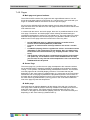
Local Settings
Sort in lists: here you choose on which way the outputs and functions will be
sorted in a PROSOFT screen list. This setting is no setting in the .NBT file but will
be generally kept for PROSOFT Suite.
TV, Radio, Camera settings: here you can regulate the frequencies for TV/Radio
channels and cameras (for use on the SERVUS touch screens). Also the DTMF
codes for the door opener and speach can be determined.
Import TV/Radio settings of another .NBT file: if you have several installations in
one region (same channel classification on the cable /antenna) you easily can
import the Radio and TV settings from another existing .NBT file.
22
TELETASK Handbook
PROSOFT >
Rooms
5. The rooms
5.1. Introduction
Every home is divided in several rooms: the kitchen, living room, the office room, the
bathroom(s), the different sleeping rooms, the garden, etc… Because this is a clear
and logical approach for every home,PROSOFT also approaches your home by using
the different rooms.
The defined rooms are also very important for the automatic generation
program of some of the menu operated TELETASK user interfaces
(mobile phone iSGUI interface). It is very important to insert the rooms
correctly!
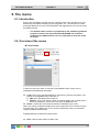
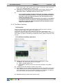
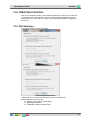
5.2. Overview of the rooms
List of rooms
In the list of rooms you have an overview of all available rooms. Every room is
substituted of the following information:
'Code': Every room gets automatically a code which is used by the system. This
code is not changeable and is made out of:
'RM': this is the abbreviation of 'Room'
'Number': every room gets a number for internal system use. It starts with 01
and is incremented (+1) every time you enter an additional room.
'Name': contains the room name as entered in PROSOFT by the user.
When you want to change an existing room name, select the room in the list of rooms.
It will turn blue. Then double click on it or click the 'edit' button. Now you are able to
change the different parameters.
Possible actions in the list of rooms menu
'New': Click the 'New' button to add a room.
23
TELETASK Handbook
PROSOFT >
Rooms
'Edit': Click the 'Edit' button to edit the parameters of a room
'Delete': Click the 'Delete' button to delete a room from the list of rooms.
In practice
Click 'Edit' in the PROSOFT menu bar.
Click 'Rooms'.
The 'list of rooms' window appears on the screen
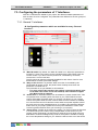
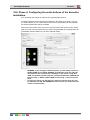
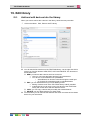
5.3. Adding rooms to the list of rooms
The different parameters for every room
'Name': Enter the name of the room (short and easy to understand and to locate
name).
'Audio Zone': If you have an audio system integrated with your TELETASK
system, you will have to connect the room to a specific audio zone (amplifier).
You will have to select this audio zone later, after the audio interface
and the audio zones on this interface have been defined. Please refer
for more information in the 'Audio Interfaces' chapter, but we
recommend not doing this right now.
'Sensor Zone': If you are using TELETASK temperature sensors for heating
and/or cooling control (recommended), select the applying sensor zones with
which the room is to be related.
The sensor zones are entered when the sensors are entered in
PROSOFT. So please also come back here later, as soon as the
sensors for your project are entered. For more information refer to the
'Analogue Input Interfaces' chapter.
In practice
Click 'Edit' in the PROSOFT menu bar.
Click 'Rooms'.
The 'List of Rooms' window appears on the screen. In this screen the standard
rooms are reproduced.
Click the 'NEW' button to add a room to your project.
The 'Define Room' window appears on your screen. Set up the different
parameters for this room.
Click 'OK': now a room is added to your TELETASK domotics project. The
window 'Define Room' will disappear.
In the 'List of Rooms' which is visible again, the added room is displayed.
24
TELETASK Handbook
PROSOFT >
“O” Units: Outputs
6. 'O' Units: Outputs
6.1. General notes
6.1.1. Output
An output connects one electrical load or circuit with the TELETASK system. Thanks
to this connection, you can control this load out of the domotics system. There are
three different groups of outputs.
'Relay': this output switches a load between the 'ON' (relay contact is closed) and
the OFF (relay contact is open) status.
'Dimmer': this output varies an analogue output signal from 0 to 10Volt. This
signal is mostly used to control a power dimmer. 0V output means the dimmer is
at 0% (load is off). 10V on the output means the dimmer is at 100% (the load is
ON). This means that a light or group of lights connected to the power dimmer are
OFF or ON or dimmed somewhere between 0 and 100%.
In stead of 0-10V, this may also be 1-10V, 0-100% (for example when using a
DMX output interface).
'Motor': this output controls a motor rotating left or right during a limited number
of seconds. The motor can also be stopped at any time. So this output can be set
in the LEFT/ RIGHT or STOP status. LEFT/RIGHT can also be considered as
UP/DOWN, depending on the connected motor (in most of the cases this is for
control of electrical motorised curtains, sun blinds and shutters).
6.1.2. Output unit
Outputs with the same functionality and the same technical specifications are brought
in to groups per output unit. The output units can be divided in two different
breakdowns:
- Based on their function (relays, dimmers, motors)
- Based on the system relation (integrated in the MICROS+ central unit, external but
plug-in on the MICROS(+ upgrade version) central unit and externally connected via
the AUTOBUS).
Functional classification
'Relay Output units': groups of eight (8) relays of the same type
'Dimmer Output units': groups of eight (8) dimmer control outputs of the same
type.
'Motor Output units': groups of four (4) motor control outputs of the same type.
System related classification
The output units can also be grouped depending on the way they are connected with
the TELETASK central unit. There are two system related categories:
'Standard Output units': these output units are integrated in the central unit
(only in case of MICROS/PICOS central units). Refer to the data sheet of your
central unit for more detailed information.
'AUTOBUS Output units': these types of output units are all output interfaces
with an AUTOBUS connection. For example TDS13500, TDS13524, TDS13525,
TDS13608…).
Remark: All AUTUBUS in- and output units are in general also called in- and
output 'interfaces'.
6.1.3. Output numbers
Every output which is defined in PROSOFT automatically gets an output number.
Once an output has been given an output number, this number can not be changed
25
TELETASK Handbook
PROSOFT >
“O” Units: Outputs
any more during the project, even if the address of an output interface (for addressing
see later in this text) would change during the project.
The numbering starts for the three functional groups (relays, dimmers and motors) all
starts with number '1'. Depending on the kind of output, PROSOFT will add in front of
the number the abbreviation 'REL' for relay, 'DIM' for a dimmer and 'MOT' for a motor
output.
When there are several central units connected, you will also have to add a letter
which indicates to which central unit the output is connected. (from A to J, because
there can be coupled up to 10 central units to each other over IP).
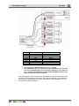
6.1.4. 'O' Address (Output Address)
For all interfaces connected to the AUTOBUS, so also for the output interfaces on
AUTOBUS, it is necessary to the system to be able to distinguish the different
interfaces from each other. Therefore every AUTOBUS interface has a hardware
address setting.
The address numbering starts at '00'. This address is reserved for the central unit.
So in a practical situation, the address setting will always start with a higher number.
This is also because the central unit has other predefined address settings for its
internal (general) outputs. The number of predefined (reserved for the system)
addresses, depends on the type of central unit you use and they will be reserved
automatically in PROSOFT.
PROSOFT automatically assigns an address to every new defined output unit. You
will have to set the same address on the hardware interface (connected on
AUTOBUS) as the address given in PROSOFT. If the hardware AUTOBUS address of
an interface has been set to a certain address already, you can change the address in
PROSOFT.
Additionally, PROSOFT assigns for internal use an 'O' letter to the address. This way
it is clearly noted that this concerns an Output address on an Output interface. This is
necessary because there are also AUTOBUS Input addresses. These 'I' addresses
are freestanding of the 'O' addresses. This means that 'O16' and 'I16' can exist on the
same AUTOBUS. Within the 'O' and 'I' addresses each address setting must be
unique. So there may be no two 'O16' addresses because the system can not
distinguish these two from each other and the system will not behave properly in such
case. Hardware damage will not occur due to double addressing, but outputs behave
unpredictable. Refer to the 'I interfaces' chapter for more information on 'I' addressing.
The number of addresses available on the AUTOBUS is limited. The highest settable
output address ('O' address) is defined by the limits of the concerning central unit you
use. Please refer to the data sheet of your central unit for system limits.
IMPORTANT REMARK: Using double addresses is not allowed and can
generated danger and non secure situations. So always check very
carefully before powering your system if no double addressing occurs.
6.2. Adding Output units
When you start-up a new TELETASK project, you will have to choose for a certain
central unit. By selecting the central unit, PROSOFT automatically generates all
standard available internal Output Units of the central unit. When you need more
output units than the ones available in the central unit (MICROS+), you will have to
add extra output units. the AUTOBUS output interfaces have to be added in
PROSOFT by the user. When adding the output units, there are four parameters to be
set:
6.2.1. The different available parameters
26
TELETASK Handbook
PROSOFT >
“O” Units: Outputs
New: Choose if the Output Unit which you want to add is a 'Relay output unit', a
'Dimmer output unit' or a 'Motor Output unit'.
Be sure that you take the right functional group. Later it is not always
simple to change an existing group to another functional group. You
will have to delete the wrong group and add a new (correct) group.
Settings of the deleted group will be lost.
'Address': This setting is done automatically by PROSOFT, but you can always
change the address if the concerned interface was already given another
(available) hardware address setting.
Tip: It is always easier and faster to change the address setting of an interface in
PROSOFT than changing it somewhere in an electrical cabinet or in a wall
mounted panel.
'Type of Output': Select here the exact type of output, based on the concerning
TELETASK reference (for example TDS13500).
'Name': enter in this field a short and understandable name for the output. In
most of the cases you can just leave the name as it is given by PROSOFT. If you
have more than one electrical cabinet at different locations in your project, we
recommend to add to the output numbers (for example '25-32') the name of the
floor of the electrical cabinet wherein the output unit is installed.
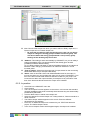
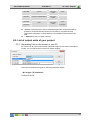
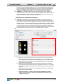
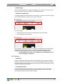
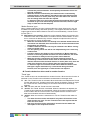
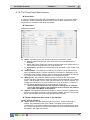
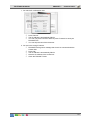
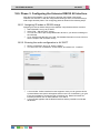
6.2.2. In practice
Click 'Edit' in the PROSOFT menu bar.
Click 'Outputs'
.
The 'List of Outputs' window appears on the screen. In this screen the standard
(internal) available output units are already there because they are automatically
predefined by PROSOFT.
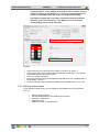
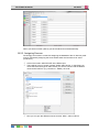
Click the 'New' button to add an extra output unit.
Select the desired 'Functional Output unit': 'Relay Interface', 'Dimmer Interface' or
'Motor Interface'.
The 'Define Output' window appears on the screen. Enter the different
parameters for this interface.
Click 'OK': an additional Output unit is entered to your TELETASK domotics
project. The 'Define Output' closes.
In the 'List of Outputs' window which appears again, the output unit is added.
27
TELETASK Handbook
PROSOFT >
“O” Units: Outputs
Repeat this way of working for all TELETASK output units which are to be added
to your project.
6.3. Assigning TELETASK Outputs.
An important step to fluently parameterise your project is the assignment of a name for
all individual outputs (relays, dimmers, motors). In a later stage it will be a continuous
job to use these assigned names when defining relations and functions. The assigned
name of an individual output will always refer to the connected load or circuit.
For example: 'main light' (in the kitchen), 'wall sockets' (in the home office) or 'left
curtain' (in the living room).
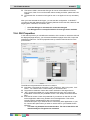
6.3.1. The different available parameters:
In the 'Define Output' window of the concerned Output unit of which the output that
has to be assigned is part of, you can enter the name of all individual outputs. The
name exists out of three parameters which are to be defined:
'Room': Select the room where the load is installed.
If the room is not in the list of rooms yet, you can directly enter a new
room via the 'New' button.
If you have to change the characteristics of an existing room, you can
use the 'Edit' button.
'Icon': This is a way of grouping outputs on graphical TELETASK interfaces like
the SERVUS and ILLUS touch screens, but also for TV-interface and other
graphical user interfaces. The different 'icon' buttons are used on these interfaces
and are a way of easily finding a specific load on a touch screen. The different
available icons are:
'Not visible': the output will not be visualised on graphical interfaces. This is
to be used for all technical outputs which are not to be controlled by the user.
For example: A water valve which is mostly controlled by timers and by the
access control functions.
'Wall sockets': Select this option for outputs which are controlling wall
sockets (all general non dedicated wall sockets, cooker hood; micro wave,
fans, coffee machine, …) and other general on/off devices which are to be
controllable by the occupants of the project, like there are garden sprinklers,
etc...
'Light': Select this option if the concerned output is controlling a light or a
group of lights.
28
TELETASK Handbook
PROSOFT >
“O” Units: Outputs
'Heat/cool)': Select this option for all sensor related outputs (valves for
heating/cooling, circulation pumps of your heating/cooling system
These outputs will not be visualised on the graphical interfaces.
'Motor (Power)': Select this option when you control ('old' way of working
without the dedicated motor interfaces from TELETASK) the output 'power'
signal of a motor.
These outputs will not be visualised on the graphical interfaces
'Motor (Direction)': Select this option when the output is controlling the
direction of a motor ('old' way of working without the dedicated motor
interfaces from TELETASK)
Outputs, who are assigned to this Icon, will be visualised on graphical
interfaces under this icon, to be able to control motors for curtains and
shutters and similar up/down or left/right systems.
All motor outputs on the TELETASK dedicated motor interfaces (TDS13524,
TDS13525) are automatically assigned to a 'motor' icon.
'Name': Enter a short name of the load/circuit which is connected to this individual
output. Remember that this name will appear on the graphical interfaces (if there
are any in your project) and there is a limited room on the screens to display this
name. So keep the name length as short as possible.
Examples:
1. 'light in the parents bedroom' is not a good name, because the room
identification is already done in the 'room' section, so it would be better to use
'main light' or 'main', because the user already knows also that it concerns a 'light'
because it has been assigned to this function also.
2. 'Ambient light', 'left sockets', 'sprinklers left', 'staircase to cellar' are good
names. 'Colour lights on staircase to first floor' is not good, because it is too long
to be displayed. 'Staircase light' would be better.
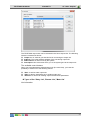
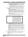
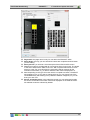
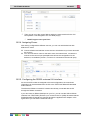
6.3.2. In practice:
Click 'Edit' in the PROSOFT menu bar.
Click 'Outputs' in the 'Edit' pull down menu
Select the desired Output unit by clicking on it. The selected output unit turns
blue.
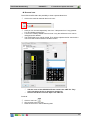
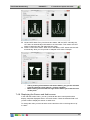
Click the 'Edit' button. The 'Define Output' window appears.
Click on the picture of the interface the desired individual output. The selected
output turns yellow.
Select/enter in the 'Output name' field one by one the 'Room' of the load, the
related 'Icon' and enter the name you want to be displayed.
Click 'OK', the selected individual output is ready for later use.
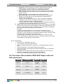
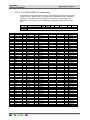
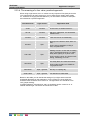
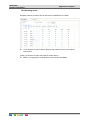
6.4. Overview of the available TELETASK Output units and
their parameters
TDS ref
Functional
Address
Options
TDS13500
Relays
With rotary
switch
Power*
TDS13501
Relays
With rotary
switch
Power*
TDS13502
Relays
With rotary
switch
Power*
TDS13603
Dimmer DMX
With rotary
switch
Power*
29
TELETASK Handbook
PROSOFT >
TDS13608
Dimmer
With rotary
switch
TDS13610
Dimmer FLUORESCENTIE
With rotary
switch
Motor
With rotary
switch
TDS13524
TDS13525
“O” Units: Outputs
Power*
Power*
Power*
Pulse time*
* Power: Information field. Can be entered for light bulbs so the information is
printed on the printed documents and can be used by occupants as lamp
replacement information. Values between 0 and 30000 can be entered in this
field.
** Pulse time: See 'Functions'- 'Motors'
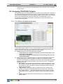
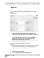
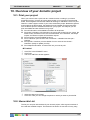
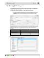
6.5. List of output units of your project.
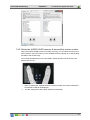
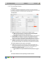
6.5.1. Generating Lists on the screen of your PC
An overview of all output units and their individual output can be made in several sort
modes. You can find the lists in the 'list of outputs' window.
There are four different list types for searching individual outputs.
List type ''O' Interfaces':
Content of the list
30
TELETASK Handbook
PROSOFT >
“O” Units: Outputs
The TELETASK output units can be reviewed in the 'list of outputs' list. The following
items are contained in this list:
Output: the 'O' reminds you that this line is concerning an Output unit.
Address: This is the software address of the concerning output unit.
Abbreviation: for internal use by the system.
Description: this is the name which you or the system gave to the output unit.
The available control buttons:
When you have selected the desired output unit (line turns blue), you have the
possibility to select one of the following actions:
'New': to add an extra output unit.
'Edit': to edit the parameters of an existing output unit.
'Remove': to remove an existing output unit and all its parameters.
Types of list: 'Relay List', 'Dimmer List', 'Motor list'
List information
31
TELETASK Handbook
PROSOFT >
“O” Units: Outputs
Functional Group: indicates to which functional group the output belongs
'REL': a relay (classified in the 'Relay list')
'DIM': a dimmer (classified in the 'Dimmer list')
'MOT': a motor (classified in the 'Motor list')
'Output Number': contains the output number which was automatically given by
PROSOFT
'Room': is the room to which the individual output is connected.
'Icon': the icon to which the individual output is connected.
'Name': the name of the individual output.
Actions
When you have located the desired individual output, you can select it by simply
clicking on it (turns blue). The following actions can be done from here:
'New': depending on the list wherein you are, there will be four motors or eight
dimmers or eight relays added to the output list. They will get the numbers which
are the smallest available in the system.
'Edit': click 'edit' to open the 'define output' window. You can now edit the
parameters of the selected individual output.
'Test Online': when your computer is online (connected) to an operational central
unit, you can control the selected output via this button. At the same time the
actual status of the output is displayed.
Relay: Select the desired status 'on' or 'off' and Click on the 'Switch' button to
bring the output in the desired status.
Dimmer: Select the desired status 'On' (= 100%), 'Off' (=0%) or a value in
between and Click on the 'Switch' button.
Remarks
The 'Test Online' option is only available when at least a powered
TELETASK central unit is connected to your PC. If this is not the case,
their will be a 'no connection' message in the 'Test Online' window.
A motor can not be tested on line.
Sorting of lists:
Possible list sorting
32
TELETASK Handbook
PROSOFT >
“O” Units: Outputs
The list types of relays, dimmers and motors can be sorted as follows:
'No sorting, show in numerical order': Sorted on output number (numerical
order). This is the default setting.
'Sort by room, icon and name': All outputs are now sorted by room and
secondarily by icon and then by name (all in alphabetical order)
'Sort by icon, room and name': All outputs are now sorted by icon and
secondarily by room and then by name (all in alphabetical order)
In practice:
Click 'Extra' in the PROSOFT menu bar
Click 'Options' in the 'Extra' pull down menu and the 'Options' window appears
Click the 'Local Settings' tab.
Select in the 'Sorting of the lists' the desired sorting mode.
Click 'close' and the sorting mode is active. You can see the outputs sorted in the
new mode now if you go to the list of outputs.
33
TELETASK Handbook
PROSOFT >
“I” Interfaces: Inputs and other
7. 'I' units: Inputs and other
7.1. General notions
Before you can enter all inputs and input units (= 'I' units) in to your TELETASK
project, it is essential to have a good understanding of some basic items.
7.1.1. 'I' interfaces: Inputs and other
In contrast with the 'O' interfaces, the 'I' interfaces are less conveniently arranged
because there is a wider range of input units and input interfaces available.
Additionally, interfaces which may be both input and output are added to the inputs
list.
As with the 'O' units, the 'I' units are divided in a functional as well as in a system
related way.
Functional classification
There are four different types of input units.
'General inputs': these are all TELETASK (AUTOBUS connected) touch panels,
touch screens, etc… (See more details in the overview list further in this text).
When somebody pushes a button on a touch panel, a command is sent to the
central unit, and the predefined action for this button is done.
'Digital Inputs': digital inputs are contact inputs for all kind of external on/off
signals like there are from standard voltage free push buttons (any brand), motion
detectors (often via a relay to be connected to the voltage free contact inputs of
the TELETASK input). When the concerned external contact is closed, the input
unit or interface generates the related command and the central unit processes
this command just like it was coming from a touch panel and the predefined
action is done.
'Analogue Inputs': analogue inputs are the connection between the TELETASK
system and the three different kinds of TELETASK sensors. The sensors send
their signal to the analogue input (internal in the central unit or external on
AUTOBUS). This signal is continuously processed by the central unit and
depending on the related function actions are taken at certain times.
'Audio/Video interfaces': This is a whole family of different general and
dedicated (brand dependant) interfaces. All audio interfaces are AUTOBUS
interfaces. By these interfaces it becomes simple to control connected audio
systems with standard buttons and/or special touch panels and touch screens.
System classification
Beside of the functional classification, the 'I' interfaces can also be classified based on
the way they are connected with the TELETASK central unit.
There are two groups to be distinguished:
'Direct or Internal 'I' Interfaces': these 'I' interfaces are integrated in the central
unit. Depending on the type of central unit you use, there may be different types
of internal 'I' interfaces available in the central unit. Please refer to the concerning
data sheet of your central unit for more details.
'AUTOBUS 'I' Interfaces': these 'I' interfaces are connected on the AUTOBUS.
Most of the 'I' interfaces are of this kind (TDS12116, 16 digital inputs for voltage
free contacts).
7.1.2. 'I' Address:
The address setting is necessary for the system to be able to communicate with the
individual interfaces and modules. Every 'I' unit and interface has its own address. All
34
TELETASK Handbook
PROSOFT >
“I” Interfaces: Inputs and other
external AUTOBUS connected 'I' interfaces have a hardware or software address
setting on the interface itself (just like Output interfaces).
The address numbering starts with an 'AUTOBUS number'. Then PROSOFT ads for
internal use an 'I' to the address. This way it will be very clear in PROSOFT that it
concerns an 'I' interface. This is necessary because there are also TELETASK
AUTOBUS 'O' interfaces which become an address (these are the output interfaces).
These 'O' addresses are unrelated of the 'I' addresses. This means that there can be
an 'O16' and an 'I16'. In the 'O' and 'I' address groups every address is unique. There
can't exist 2 'O16' addresses or 2 'I16' addresses.
The actual 'I' address starts with '00'; these are the Master functions on the remote
control. The first address which can be defined on an interface is '01'. ). PROSOFT
automatically generates an address for every new 'I' interface which is added to the
system. Be sure that this address is created for the 'I' interface or that the set-up in
PROSOFT can be adapted to the set-up of the 'I'interface. Differences between the
hardware (on the interface) address setting and the software (PROSOFT) address
setting can result in erroneous and unpredictable behaviour of the system. Please
check this before starting-up the TDS system.
Some TELETASK interfaces use more then 1 address (f.e. the
TDS12116 is a 16 input digital input interface, and occupies two
AUTOBUS addresses. Only the first address of this input interface can
be set-up in the hardware. The other addresses follow up this hardware
set-up address and will automatically be assigned by PROSOFT.
To avoid errors in your configuration it is recommended to let
PROSOFT decide what the addresses are. PROSOFT automatically
takes care of multiple addressing and will avoid making errors about
this.
The standard 'I'interfaces (f.e. TDS10012 MICROS+) start on AUTOBUS
0.
IMPORTANT REMARK: Using the same addresses twice on one bus is
not allowed and can generated danger and non secure situations. So
always check very carefully before powering your system if no double
addressing occurs (two or more interfaces are set to the same
hardware address).
7.2. Adding TELETASK 'I' interfaces
When you start a new TELETASK project you have been choosing the central unit. By
doing this, PROSOFT automatically generates all standard in the central unit available
(internal) digital and analogue inputs (and outputs).
PROSOFT also adds an input unit called 'Master' functions. These are the Master
functions which can be allocated for extra eight functions on the TELETASK remote
control.
When you need additional inputs (like in most of the cases) than the ones standard
available at a central unit, you will have to add extra input interfaces.
When adding interfaces, there are four different parameters to be set:
7.2.1. Parameters for adding new 'I' interfaces:
35
TELETASK Handbook
PROSOFT >
“I” Interfaces: Inputs and other
'Group': Choose the (functional) group to which the new 'I' interface belongs:
'General Interface', 'Digital Input Interface', 'Analogue Input Interface' or 'Audio
Interface'.
Be sure to choose the correct group, because it is not possible to
change an interface from one group in to an interface of another group
any more. In such case, you will have to delete the wrong interface first
and then add the correct one.
'Type of Input': select the interface you want to be added. The interfaces are
shown in the list sorted by their individual TDS reference.
New interface. The address can be changed by the user at any time if you want.
PROSOFT takes care of impossible or not allowed address settings. So if you
change the address to a not allowed address, PROSOFT will not allow you to do
any changes on the address setting.
'Name': enter here a description of the location where the interface is installed
together with the inputs numbers which are already entered y PROSOFT (if it is a
contact input interface).
7.2.2. In practice:
Click 'Edit' in the PROSOFT menu bar.
Click 'Inputs and other'.
The 'Interface list' window appears on the screen. The standard 'I' interfaces are
displayed here.
Click the 'New' button to add a new 'I' interface to your project.
Click the desired functional group: 'General Interface', 'Digital Input Interface',
'Analogue Input Interface' or 'Audio Interface'.
The 'Define Interface Function' window appears on the screen. Configure the
parameters of the concerning interface (see below for more details).
Click 'OK': the 'I' interface is added to your TELETASK project and the window
'Define Interface Function' is closed.
The new interface is added in the 'Interfaces list' window.
Repeat this way of working for all TELETASK 'I' interfaces which you want to
appear in your project.
36
TELETASK Handbook
PROSOFT >
“I” Interfaces: Inputs and other
7.3. Configuring the parameters of 'I' Interfaces.
After all 'I' interfaces are added to your project, the different settable parameters of
each of them are to be configured. The parameters are different for the four groups of
'I' interfaces:
7.3.1. General 'I' interfaces
Configurable parameters which are available for every 'General
interface':
'Main IR enable': By default, the 'Main IR enable' is on. When this parameter is
marked ('V'), then every button can be controlled with the TELETASK infra red
remote control. If you don't want the panel to be controllable by IR remote,
remove the 'V' mark in this field.
The IR control can also be individually disabled for each button. See for more
details below at 'button' parameter settings.
'Beep on IR': Marked 'V' by default. When a function is controlled by the
TELETASK IR remote control, the panel buzzer will beep short when this
parameter is marked with 'V'.
This parameter is not yet available on all interfaces.
For some of the older interfaces this setting is done by hardware (refer
to the data sheet of the concerned interface). New interfaces support
this 'Beep on IR' by software.
'Audio Zone': A 'General interface can be related to a certain 'Audio Zone'. This
is important when controlling audio functions on your TELETASK IR remote
control (TDS12502). Example: when you click the 'CD' button on your remote
control, the system needs to know in which audio zone the interface is installed,
so it can start the correct CD and the correct audio zone power amplifier. Select
the audio zone from the predefined zones. If you didn't yet entered the different
audio zones in your project, please do so first (in the PROSOFT screen of the
concerning audio interface which you are using in your project).
'Sensor Zone': Familiar to the audio zone setting, you must connect the interface
to a certain sensor zone. When using a temperature control function on your
remote control (TDS12502), the interface (for example a touch panel) must me
dedicated to a certain heating/cooling zone for the system to be able to change
the correct temperature setting for you. Select the Sensor zone out of the sensor
37
TELETASK Handbook
PROSOFT >
“I” Interfaces: Inputs and other
list which you have entered already or, if not, add the temperature sensors and
their zone names first before proceeding here. Sensor zones are defined at the
level of the analogue (sensor) input unit. Look also in the thematical chapter
'setting up a heating/cooling system' for more information on this subject.
'RGB Zone': in this field you can link a multi-colour lighting zone (RGB) to a
'General Interface'. This means that the selected RGB function will be controlled
when you activate it with the remote control when pointing at the IR receiver of
the General Interface. (when using the TDS12502)
Parameter per individual button/input:
Relations: The definition of the functional features of a 'General Interface' is
mainly defined by the relations between the inputs (for example the buttons of a
touch panel or contact inputs of a digital input interface) and the outputs (relays,
dimmers, motors…) of the system. Due to the characteristics of a relation decide
what the actions are to be done after pushing a button or closing an input contact
of a general input interface. Additionally there may be two different relations for
every input (button or contact). There is a possible relation for pushing 'short' and
another relation for pushing 'long' on the concerned button / contact:
'Short': the function behind the 'short' action will be used to be processed
when the user pushes only briefly (by default less than 1.5 seconds) on the
concerning button or when the concerned input contact is only closed briefly.
Refer to the chapter 'Functions' for more detailed description of all possible
functions which can be used.
'Long': the function behind the 'long' action will be used to be processed
when the user pushes longer than 'short' (by default more than 1.5 seconds)
on the concerning button or when the concerned input contact is closed for a
'long' time.
Refer to the chapter 'Functions' for more detailed description of all possible
functions which can be used.
Refer to the 'Extra' - 'Options' menu in this handbook for custom
setting of the 'short' time definition. TELETASK recommend not to
change this setting.
38
TELETASK Handbook
PROSOFT >
“I” Interfaces: Inputs and other
There are two differences about time settings for short/long. The time
on all inputs and buttons of general interfaces and the time setting for
internal contact inputs in central units:
'LONG push on general interfaces': This time can only have two settings:
1.5 or 3 seconds. This setting is automatically adapted to the value of
the direct input Long push.
'LONG pushing internal contact inputs': To be set between 1 second to 5
seconds in steps of 0.5 seconds. By default this time is 1 second.
TELETASK recommends not changing any of these default settings.
'Button': In this field there are two more settings possible for each individual
button/input:
'Enable Remote Control': when this parameter is marked 'V' (default), than
you can control the individual button or contact input which is currently
selected on the picture of the interface.
Buttons/contacts 1 to 8 are on the picture of the interface and can be
selected by clicking on them with the mouse pointer. The IR remote control
activates the same buttons as the ones on the wall panel or input interface.
The 'short' and 'long' pushing differences are the same on the IR remote
control than the ones configurated on the 'I' interface (touch panel or input
interface).
This item is marked by default.
If your 'I' interface has more than eight buttons or inputs, the IR remote
control controls the first 8 of them. There may be exceptions on this rule.
Please refer to the data sheets of the concerned interface.
IMPORTANT REMARK: Remove the ‘V’ mark
when you control a door opener or another
security related item with that particular
button. Otherwise anybody having a remoter
control and standing outside may be able to
open your door via a remote control which is
transmitting trough a window or any other
visual open surface. For security and safety
reasons this is absolutely not allowed and
must be avoided in any case! It is the
responsibility of the programmer of the system
that these and comparable actions are to be
blocked.
'Enable Button Control': this parameter is working for the buttons on the
touch panel or the inputs on the input interface. It is similar to the 'enable
Remote Control'. By default this parameter is marked for all individual
buttons/contacts. So when somebody pushes a button which is not marked at
the 'Enable Button Control' nothing will happen. The relation of that button,
although it is defined, will not be processed because the button activity is
disabled.
Disabling the button function is seldom used, but is for example usable if
visitors are not allowed to control something in the house. The occupant can
for example control that function with a remote control. Can be useful in public
areas.
'Couple Vertically/Horizontally': In some general interfaces it is possible to
use two buttons to control only one function. For example, to control a
dimmable light or a motorized curtain.
'Info': This is a text field for your information only (on screen and on paper). You
can enter a specific description here about the location of the concerning
interface.
Example: 'touch panel in the bath room first floor' or 'interface mounted in
electrical cabinet L101'
39
TELETASK Handbook
PROSOFT >
“I” Interfaces: Inputs and other
'Engraving': If you want to order a custom engraving for one or more buttons on
touch panels who apply to this, like TDS12005xx, TDS12008xx, TDS12016xx or
TDS12017x, you can complete the engraving field (2 x 7 characters). Send the
PROSOFT file to your TELETASK supplier and he will supply you the necessary
buttons with custom engraving. Please do not forget to mention together with your
order the colour of the button you want to be supplied (several colours are
possible; white, black and grey are standard). (not applicable for the
TDS12001/TDS12015/TDS12021/TDS12022).
In practice:
Click 'Edit' in the PROSOFT menu bar.
Click 'Inputs and other'.
Select the desired 'general interface' by clicking on it
Click the button 'Edit' and the 'Define Interface Function' window appears on the
screen.
Tune the 'General Interface' parameters 'Global IR', 'Audio Zone' and 'Sensor
Zone'
Select each individual button/input on the interface picture on your screen.
Select in 'Short' and/or 'Long' the desired function type. Refer to the 'Functions'
chapter for more details about the different available functions.
Select the connected output or function for that relation for the short and/or long
function.
It may be necessary to enter extra function depending parameters.
Do this for every individual button/contact of the interface.
Click 'OK' until you are back in the main menu of PROSOFT.
40
TELETASK Handbook
PROSOFT >
“I” Interfaces: Inputs and other
7.3.2. Digital Input interfaces.
The different available parameters
De adjustable parameters of the digital input interfaces are the same as these of the
'General Interfaces'. Depending on the selected interface, the following parameters
can be added in the 'Button' field:
'Invert Input': when this parameter is marked with a 'V', the input will work
inverted. So the central unit is not taking action when the contact is closed (for
most of the functions) but when the contact opens.
This is most often used when a NC (Normally Closed) contact is connected to the
input.
'Edge triggered': when this parameter is marked with a 'V', the 'short' and 'long'
names will change in to 'on closing' and 'on opening'.
'On closing': the coupled action is processed at the moment that the contact
closes and for as long as the contact remains closed (or the button remains
pushed in case of a normal open contact).
'On opening': the coupled action is processed on the moment that the
contact opens or the button is released (in case of a normal open push button
contact).
In practice
Click 'Edit' in the PROSOFT menu bar.
Click 'Inputs and other'.
Select the desired 'digital interface' by clicking so it turns blue.
Click the 'Edit' button. The 'Define Interface Function' window appears on the
screen.
Enter the different 'Digital Interface' parameters 'Global IR', 'Audio Zone' and
'Sensor Zone'.
Select the desired individual input on the picture of the selected digital interface.
Select the desired function type in the 'Short' and/or 'Long' field. Refer to the
different available function type in the 'Functions' chapter.
Furthermore select the output which is to be controlled or the function which is to
be processed by the 'short' or 'long' button pressing.
Define function specific parameters if necessary.
41
TELETASK Handbook
PROSOFT >
“I” Interfaces: Inputs and other
Define other desired button specific parameters.
Now the relation between the selected input and output(s) is defined.
Click 'OK' until you are back in the main PROSOFT screen.
7.3.3. Sensor Heat/Cool interface
The different available parameters
'Sensor definition' field
'Sensor Type': this parameter defines the type of sensor which is connected to
the concerning analogue input. There are several different types of sensors which
can be connected.
'Temperature sens.': Select this sensor if you have connected a TELETASK
temperature sensor TDS12250 to your analogue input.
By using a TDS12021/TDS12022 AURUS family touch panel the built-in
temperature sensor will be configured the same way as another
temperature sensor.
'Humidity sens.': Select this sensor if you have connected a TELETASK
humidity sensor TDS12260 to your analogue input.
'Light sensor (dark)': Select this sensor if you have connected a TELETASK
light sensor TDS12270 to your analogue input, which is set (hardware setting)
as a 'dark' light sensor. Refer to the data sheet of the TDS12270 for details
about this setting.
'Light sensor (normal)': Select this sensor if you have connected a
TELETASK light sensor TDS12270 to your analogue input, which is set
(hardware setting) as a 'normal' light sensor. Refer to the data sheet of the
TDS12270 for details about this setting.
'Light sensor (sun)': Select this sensor if you have connected a TELETASK
light sensor TDS12270 to your analogue input, which is set (hardware setting)
as a 'sun' light sensor. Refer to the data sheet of the TDS12270 for details
about this setting.
Remark: the hardware settings of the light sensor are to be done by
setting the appropriate jumpers like described in the TDS12270 data
sheet.
'DAIKIN, Airzone, Mitsubishi Electric sensor':These sensors are only
available on the specific interface.
42
TELETASK Handbook
PROSOFT >
“I” Interfaces: Inputs and other
'General linear sensor': these sensors are only available on the TDS12310.
With this every type of linear sensors can be read with a standard analogue
output signal (0-10V, 4-20mA,…) This sensor gives an average value
(=sudden changes are not directly noticed)
'Wind sensor': These sensors are only available on the TDS12310. With this
every type of linear sensor can be read by an analogue output signal (0-10V,
4-20mA,) this sensor reports advanced changes immediately! (f.e. by
measuring blasts of wind)
'Sensor Name' or 'Sensor zone': In this field you can enter the name of the
sensor. This should be the temperature / light or humidity zone for this sensor.
Example: 'ground floor', 'bath room', 'bedroom Lucas', 'South sensor', 'Twilight
East'. If it concerns a temperature sensor which controls only the temperature of
the room where the sensor is installed, then the name is the room name. If the T
sensor controls several rooms, than the name may be 'ground level' or 'sleeping
area' or something similar. Keep the name short, because this name is to be
displayed on the LCD/VFD displays and touch screens which have a limited
number of characters available for the name of the sensor zone.
'Compensation': This parameter is only available when you selected a
temperature sensor in the sensor type field. The content of the compensation
field defines an offset to the measured temperature value. The TELETASK
system can work with compensation temperatures between -5°C and +5°C in
steps of 0.5°C. This compensation is default set to -2°C and is advised not to
be changed.
The 'Properties' field
After selecting a 'sensor type', different fields appear in the 'properties' window. The
possible parameters for this field are: The following parameters can be entered:
When a temperature sensor has been selected
'Heat – Control method': this parameter defines what kind of heating control
method is to be used. You have the following choices:
Standard relay control method: this is a traditional ON/OFF control. It
means that the concerned Temperature sensor will control the heating system
by means of one output relay of the TELETASK system. When the room has
to be warmed up, the relay (contact) will close and when the target
temperature is reached the relay contact is opened.
This is to control a valve, a circulation pump or a fan or similar item.
43
TELETASK Handbook
PROSOFT >
“I” Interfaces: Inputs and other
'On/off': select the relay which you want to use to control the connected
heating system. For example the relay that switches the electrical valve
of the heating zone 'ground floor'
Analog control: this is when your heating system is to be controlled by a 0 to
10 V analog output.
'On/off': Select here the relay which is to be switched (when necessary).
'Analogue Output (5°C difference=100% heat/cool)': Select here the
analogue (dimmer-) output which is to be used as the Analogue control
output for this Temperature zone.
4 speed (OR) control: To be used for multi speed (off/low/medium/high) fan
motors. This option is about an OR system, so it means that only one of the
controlled relays will be on at the same time.
'Low speed (at -0.5°C)': Select the relay which is to be activated (close
the contact) for low speed of the evolved fan.
'Medium speed (at -2.5°C)': Select the relay which is to be activated for
medium speed of the fan.
'High speed (at -5°C)': Select the relay which is to be activated for high
speed setting of the fan.
4 speed (AND) control: To be used for multi speed (off /low/medium/high)
fan motors. Same as for the 4 speed 'OR' control, but the lower speed output
relays will stay on if a higher speed setting is set.
'Low speed (at -0.5°C)': Select the relay which is to be on for low fan
speed.
'Medium speed (at -2.5°C)': Select the relay which is to on together with
the low speed relay, when medium fan speed is needed.
'High speed (at -5°C)': Select the relay which should be on together with
the low and medium speed relay, when high fan speed is needed.
Local Mood control: only for special applications.
'On/off': Select the local mood which is to be switched on/off when
temperature control is done.
Flag control: only for special applications
'On/off': Select the flag which is to be controlled when temperature
control is done.
More information about the control of a heating system can be found in the thematical
applications chapter in the heading 'how to integrate a heating/cooling system' further
in this document and at the chapter about the 'extra menu' earlier in this handbook.
'Cool – control method': this parameter defines which type of cooling control is
to be used. At the selection of the control method, there are some extra
parameters available. You have the choice out of the same systems as for the
heating control.
'Day Temperature': This parameter is the threshold value of the sensor as set
by the 'Day' preset temperature. This parameter can be set from 5°C to 30°C in
steps of 0.5°C. By default, the 'day temperature is set by the system to 20°C.
The 'Day Temperature' is used by the TELETASK home automation system as a
threshold for the 'heat' system. The 'Day' temperature for the cooling algorithm is
x °C higher than the 'day' temperature parameter. The difference is defined by the
'Delta Heat/Cool' parameter. In PROSOFT this 'day' temperature for the 'cool'
system is displayed in grey beside of the set 'Day' temperature which is shown at
the left of 'Heat'.
The 'Delta Heat/Cool' is changeable in the 'Extra' - 'Options' menu under the
'sensor' tab.
Stand-by Temperature' (economic energy saving preset): the 'Stand-by'
temperature is derived from the 'Day' temperature. Therefore the 'stand-by'
parameter is not the effective temperature but contains the difference to the 'day'
temperature. The 'stand-by' parameter can be set from 0.5°C to 5°C in steps of
0.5°C. Default the 'stand-by' parameter is set to 5°C.
44
TELETASK Handbook
PROSOFT >
“I” Interfaces: Inputs and other
The 'Day/Stand-by Temperature' is used by your system as a threshold
for the 'heat' system. The 'Day/Stand-by' temperature for the 'cool'
system is a changeable number of °C ('Delta Heat/Cool') plus the standby temperature parameter higher. (For Stand-by this is the Day preset
plus the stand-by temperature plus the 'Delta hot/cool'). This
'Day/Stand-by' temperature of the 'cool' system is in PROSOFT
displayed in grey beside to the 'stand-by' preset before 'heat'. The 'delta
heat/cool' parameter is changeable in the 'extra' 'options' menu, under
the 'sensors' tab.
'Night Temperature': this parameter defines the threshold value of the sensors
as set in the 'night temperature' parameter. This parameter can be set from 5°C to
30°C in steps of 0.5 degrees Celsius. By default the 'night temperature' is set to
5°C.
The 'Night Temperature' is used by the TELETASK system as a direct
threshold for the 'heat' system. In the 'cooling' system, there is an
individual 'Night' value available. This value can be set-up between 20
and 30°C but can never be less then the set-up Night temperature for
heating plus Delta Heat/Cool.
When selecting a humidity sensor:
'Humidity sensor': this parameter defines the function which is to be used at the
moment that the humidity sensor function has to be executed. Depending on the
integrated function, there will be more or less parameters to be set. Refer to the
explanation of the specific functions which can be used here in the 'functions'
chapter of this handbook. These are: 'Switch', 'Dim', 'Local Mood' and 'Flags' +
'process function'. These functions are activated, whenever there is measured a
value that is lower then the set-up value (air is too dry!) For 'Moistening' you have
to reverse it by hardware.
'Preset 1 (=day)': this parameter defines the 'day' threshold preset which is to be
used to control the related function. This parameter can be set from 0% humidity
to 100% humidity in steps of 1%. By default this preset is set to 100%.
'Preset 2 (=night)': this parameter defines the 'night' threshold preset which is to
be used to control the related function. This parameter can be set from 0%
humidity to 100% humidity in steps of 1%. By default this preset is set to 100%.
45
TELETASK Handbook
PROSOFT >
“I” Interfaces: Inputs and other
When selecting a light sensor ('dark', 'regulating' or 'sun' sensor is set):
'Light': this parameter defines the function which is to be executed on the
moment that the sensor function is activated. Depending on the function which
has been chosen, there are more or less parameters to be set. Refer to the
description of the specific functions in the 'functions' chapter. You can choose
here between the functions 'Switch', 'Dim', 'Local Mood' and 'Flags'.
'Preset 1 (=day)': this parameter defines the threshold for the 'day' preset. This
parameter can be set from 0 to 944060 Lux, according to a non-linear scale. By
default this sensor is set to 0 Lux.
'Preset 2 (=night)': this parameter defines the threshold for the 'night' preset.
This parameter can be set from 0 to 944060 Lux, according to a non-linear scale.
By default this sensor is set to 0 Lux.
When selecting a non-TELETASK humidity sensor (DAIKIN, AIRZONE,
Mitsubishi Electric):
46
TELETASK Handbook
PROSOFT >
“I” Interfaces: Inputs and other
'Properties': here is made a link between the TELETASK addresses and the
addresses of the concerned system. See the manual of the concerning
TELETASK interface/licence for more information. Here also the set-up
'Day/Night/Stand-by' presets are similar to the TELETASK temperature sensor.
When selecting a general linear sensor/Wind sensor:
'Settings': here you chose the type of signal, the unity which has to be used, the
precision, and the minimum and maximum values depending on the Properties of
the sensor.
'Low action': here you can, just like for other sensors, couple a function which will
be executed when the measured value is too low.
'Preset 1 (=day): this parameter defines the 'day' preset threshold value.
'Preset 2 (=night): this parameter defines the 'night' preset threshold value.
In practice
Click 'Edit' in the PROSOFT menu bar.
Click 'Inputs and other'.
Select the desired analogue input interface. The selected 'I' interface turns blue.
Click the 'Edit' button. The 'Define Interface Function' window appears on the
screen.
Select the desired input on the picture of the selected analogue input interface.
Select the desired sensor and set the different parameters depending on the
needs of your project.
Click 'OK' until you are back in the main PROSOFT screen. The analogue input is
defined. Don't forget to save your work regularly. TELETASK recommends
having an incremental counter in the file name you use. This way you can easily
go back to an older version if you think you have made an error in one of your last
saved versions.
7.3.4. Audio Interfaces
The different available parameters
'Audio Zone': the audio zone is a room or a group of rooms wherein the audio can
be listened coming from one audio power amplifier. Following to this, the volume
47
TELETASK Handbook
PROSOFT >
“I” Interfaces: Inputs and other
level of the rooms in the same audio zone are depending on each other. As soon
as you have been entering a name in the 'audio zone' field, the audio functions for
this audio zone are released for use in PROSOFT.
Audio zone example names: 'Bath room', 'Kitchen', 'Office', 'Bathroom parents
and dressing', 'bath rooms ground floor', 'outdoor', etc…
Add as much audio zones as the used audio interface is able to control. See for
more details in the data sheet of the specific audio interface.
For TDS14042, see chapter AV-SOFT.
In practice
Click 'Edit' in the PROSOFT menu bar.
Click 'Inputs and other'.
Select the desired audio interface by clicking on it.
Click the 'Edit' button. The 'Define Interface Function' window appears on the
screen.
Select the desired audio zone on the picture of the audio interface.
Enter the name of the audio zone.
Click 'OK' until you are back in the main PROSOFT screen. The audio zone(s) is
(are) defined now.
Overview of the available Audio Interfaces
H = hardware setting
Extension Interface = the extension interface is only to be selected if the former
address is also the address of the related basic audio interface.
System Number = to be used for some specific parameters of your audio
installation. Refer to the data sheet and the installation manual of the concerned
audio interface.
7.3.5. Overview list of 'I' Interfaces of your domotics project.
An overview list of the 'I' interfaces, the different inputs, sensors and the audio zones
in your project are easily overviewed in the different available lists. These lists are
shown in the 'list interfaces' window. Click in the main PROSOFT menu 'Edit', 'Inputs
and others' and select the desired on-screen overview list.
48
TELETASK Handbook
PROSOFT >
“I” Interfaces: Inputs and other
There are different lists which can be displayed:
List type 'I' Interfaces:
The list contains:
This list gives you an overview of the 'I' interfaces of your TELETASK project,
conveniently arranged. In this list the next items are displayed:
'Address': In the first part of the first column there is the software address of the
concerned 'I' interface. PROSOFT adds the letter 'I' to remark that it concerns an
input interface.
'Group': In the second part of the first column the input interface group
abbreviation is displayed.
'Description': the name which you have been giving to the interface.
Actions:
When the desired 'I' interface is found, you can select it and the line becomes blue
when selected. The following actions can be taken starting from this list:
'New': Click op the 'New' button to add an extra 'I' interface to your project.
'Edit': Click on the 'Edit' button to open the 'Define Interface Function' window
where you can change the settings of that interface.
'Copy': there will be made a copy of the selected interface. All settings, except for
the address, are kept.
'Remove': Click to remove the interface from your project. Be careful, there is no
undo button for this action, but PROSOFT will ask for a confirmation before it is
finally removed.
49
TELETASK Handbook
PROSOFT >
“I” Interfaces: Inputs and other
List type 'Input list'
The list contains:
This list gives an overview of the TELETASK individual digital inputs used in your
project. Next items are displayed in this list:
'INP': this abbreviation defines that the item displayed on that line is an input.
'Number': the input number is divided in to two parts. The fist part is the
AUTOBUS address of the digital input interface. The second part is the individual
input number on that input interface (for example '4' is the fourth input of 8 or 16).
'Description': contains the name you have been giving to this individual input...
Actions:
When the desired input is found, you can select it by clicking on it and it will turn blue.
The following actions can be done after selecting the input:
'New': to add an extra input to the project.
It will be necessary to add a new 'I' interface here before you can add
an individual input.
'Edit': Click on the 'Edit' button to go to the 'Define Interface Function' window to
be able to change the parameters of the individual input.
List type 'Sensor Zone' and 'Audio Zone'
The list contains:
These two lists give you an overview of all sensors and audio zones in your
TELETASK domotics project. You can find the following information in both these lists:
50
TELETASK Handbook
PROSOFT >
“I” Interfaces: Inputs and other
'Type': defines whether it concerns a sensor zone ('SEN') or audio zone ('AZN').
'Number': shows the number which was given to the sensor or the audio zone.
'Description': contains the name you have been giving to the sensor or audio
zone.
Actions
When the desired sensor or audio zone is located, you can select it by clicking on it
and it will turn blue to confirm that you have selected that line. The following actions
can be done in this case:
'New': to enter an additional sensor or audio zone.
It will also be necessary to define a new 'I' interface here.
'Edit': Click on the 'Edit' button to change the parameters of a sensor or audio
zone.
51
TELETASK Handbook
PROSOFT >
“I” Interfaces: Inputs and other
7.4. TDS12022 AURUS-OLED
An AURUS-OLED (TDS12022) differs not very much with the other TELETASK touch
panels. Here follows a complete overview with special attention to the specific
possibilities which are the result of the AURUS-OLED design.
The AURUS-OLED is available from PROSOFT Suite Version 3.2. This version of
PROSOFT or a newer version is downloadable on www.TELETASK.eu.
7.4.1. Add an AURUS-OLED
To add an AURUS-OLED to the domotics project, please follow the standard
procedure in the PROSOFT Suite.
Click in PROSOFT on the icon of the 'I' input interface or choose 'edit inputs and
others'.
Then click on 'new' and select 'General Interface'.
Choose the TDS12022: AURUS OLED out of the list 'Type Interface'.
52
TELETASK Handbook
PROSOFT >
“I” Interfaces: Inputs and other
7.4.2. Overview
Settings apply on the
complete interface.
Wwhich zones
areWhich zone is
applicable for the
remote control.
Select the orientation of
the AURUS-OLED.
Settings per
BUTTON: click in
the drawing of the
AURUS-OLED on
1 of the 8 buttons
and configure the
functions for this
button.
You can change it later
on.
Navigate through the
different pages on the
AURUS-OLED.
A complete empty page
will be displayed in
PROSOFT but NOT on
the AURUS-OLED.
Settings per
button for use by
the remote
control.
The built-in temperature
sensor.
"Edit this screen": Change the icons
and text of the buttons or draw your
own icon!
53
TELETASK Handleiding
PROSOFT >
“I” Interfaces: Inputs and other
7.4.3. Interface data (horizontal/vertical)
For the AURUS (TDS12021) and the AURUS-OLED (TDS12022) there was added an
extra option in the 'Interface data' namely the choice between 'horizontal' and 'vertical'.
This way you determine how you will mount the touch panel horizontally or vertically.
VERTICAL
HORIZONTAL
This setting can always be changed. The configured functions of the buttons won't be
deleted.
Pay attention: Always check if the notes are displayed completely on
the AURUS-OLED. By turning the AURUS-OLED the positions of the
icons and the notes will change.
Check this in the 'Edit this screen'-menu.
7.4.4. Built-in temperature sensor.
The AURUS-OLED contains a built-in temperature sensor. This can be used as
sensor zone through the complete Domotics project.
The built-in temperature sensor of the AURUS-OLED isn't activated by default. To
activate, follow the following instructions:
Practical:
Click on the sensor icon
Choose 'Temperature sensor' as Sensor type and give the sensor a proper name:
e.g.: Sensor AURUS-OLED Living.
If the sensor will be used to control a heating/cooling system, complete the
settings at 'Properties':
54
TELETASK Handleiding
PROSOFT >
“I” Interfaces: Inputs and other
7.4.5. Pages
Main page and general notions.
The AURUS-OLED contains four pages with each eight different buttons. You can
thumb through these pages by turning them in a virtual manner. Just stroke with your
finger on the hidden buttons to thumb to the next or previous page.
As soon as the AURUS-OLED has been tipped, the main page will illuminate. The
eight functions which are defined on the main page must be the functions that the end
user needs the most.
In contrast with the sensor- and audio pages, there are no predefined buttons on the
main page. The Sensor- and Audio pages contain already all needed settings to
regulate the temperature or audio on a user-friendly way. The main page on the other
hand will always depend on the domotics project. It is possible to define a sensor or
audio function on this page when this function will be used very often.
PAY ATTENTION: there is a difference between an audio-/sensor
function and a LCD/VFD (DISPLAY) FUNCTION!
A sensor- or audio function is always linked to one sensor- or audio
zone.
A LCD/VFD (display) function regulates the sensor- and audio functions
depending on the selected zone on the display. Here you always have
to foresee a zone-selection button (e.g. 'Display function: sensor: next
zone').
TIP: Program on the first page a coupled sensor function 'preset down'
and 'preset up', for the built-in sensor of the AURUS-OLED. This way
you will have an easy read out of the temperature in the room where the
AURUS-OLED will be placed.
Sensor Page
The sensor page can, just like the main page, be adapted to the customers' wishes.
As the AURUS-OLED is extremely suitable for the display and regulation of heating-,
cooling-, or fan systems, TELETASK already predefined the functions. The functions
on these pages are all LCD/VFD (display) functions. This means that they are
depending on the 'zone' button (by default button 7)! A long press on the 'zone' button
will lead the user to the page to predefine the temperature presets. The functions on
this page are all LCD/VFD (display) functions. This means that they are depending on
the 'zone' button (by default button 7)! A long press on the 'zone' buttons leads the
user to the page to preset the temperature.
Audio page
The audio page can also be adapted to all the wishes of the end user, just like the
main page. As the AURUS-OLED is extremely suitable for the display and control of
audio-and video systems, TELETASK already predefined these functions. The
functions on this page are all LCD/VFD (display) functions. This means that they are
depending on the 'zone' button (by default button 7)!
55
TELETASK Handleiding
PROSOFT >
“I” Interfaces: Inputs and other
Extra page
The fourth and last page is completely adjustable to the wishes of the end user, just
like the main page. This page contains no predefined functions.
Delete or adapt order
It is always possible to adapt the order of the pages or to restrict the number of pages
on the AURUS-OLED to only three, two or even one page.
To move a page:
Click on the page you want to move and keep the mouse pressed.
Move the page to the new place.
When deleting a page, all functions on the page will be deleted and the page will be
moved at the back. A page on which no function is predefined and which is not
followed by a page with functions, will not be displayed on the AURUS-OLED.
PAY ATTENTION: this page will be displayed in the PROSOFT Suite. It
doesn't disappear completely.
7.4.6. Buttons
General
Similar to all the other general interfaces of TELETASK you can program a specific
domotics function on every button. An overview of all possible functions, see chapter
'functions'. Next to the 'press short' and 'press long' the AURUS-OLED adds an extra,
namely the coupling of the buttons.
Coupling buttons
The AURUS-OLED offers the possibility to couple buttons with each other. When
mounting vertically the buttons can be coupled horizontally and when mounting
horizontally the buttons can be coupled vertically.
56
TELETASK Handleiding
PROSOFT >
“I” Interfaces: Inputs and other
Coupling buttons is only suitable for functions where it makes sense to
split the control over two buttons, e.g. control of a curtain/shutter, the
control of a dimmable light, the control of a temperature setting.
TIP: always consider the correct way or direction for these functions:
up/down, open/close, less/more, in the 'Edit this screen' menu the
corresponding arrows can be selected!
Practical:
Click on the first of the two buttons you want to couple. E.g.: button 1.
Select under 'short' the first half of the double button combination, f.e. a dimmer
or a Display function like 'sensor down'.
Click on 'Couple horizontally'.
Check the functions which will be automatically defined on this coupled button. In
this example = button 2.
Click on 'Edit this screen' to finish the details of the coupled buttons: icon, note.
7.4.7. Edit this screen-menu
In this 'Edit this screen'-menu you can adapt the visual details of the touch panels.
You can:
Change the page name.
See a realistic preview of the AURUS-OLED screen.
Change or create icons.
Adapt the notes.
Adapt the sensor- and audio zones.
57
TELETASK Handleiding
PROSOFT >
“I” Interfaces: Inputs and other
Page name: the page name is only for use within the PROSOFT Suite.
Show Areas: this way you can see which buttons are coupled and which button
you are editing.
Show preview: you will see a visual example of the AURUS-OLED screen.
Text: Every button is provided with an icon and two lines of text (note). The length
of the text is limited to the width of the icon. With coupled buttons there is more
place for notes. For some functions the second line will be reserved for the
indication of the status; e.g. a dimmer where the dim value is displayed in %.
Icon: depending on the type of function which is coupled to a button, PROSOFT
will suggest an icon. If you want to change this icon you can choose out of the
TELETASK library with existing icons (ranked in different categories) or you can
draw your own icon!
Sensor and audio zones: in the underlying screen you can select and reorder
the sensor- and audio zones which have to be displayed on the AURUS-OLED.
All available zones are selected by default.
58
TELETASK Handleiding
PROSOFT >
“I” Interfaces: Inputs and other
Draw an icon.
The AURUS-OLED offers the possibility to draw a personalised icon.
Click on the work bar beneath the list of icons:
Here you can choose respectively 'new icon'- 'edit present icon'-'copy present
icon' and 'delete present icon'.
A new icon is always added to the list 'user'. Only the self drawn icons can be
changed and/or deleted.
The TELETASK icons can be copied. They will be copied to the list 'users' with a
new name which was entered in the draw screen.
TIP: the icons of the AURUS-OLED are saved in the .NBT file. They
aren't lost when the file is opened on another PC.
Also the self drawn icons are kept in the .NBT file.
Practical:
Click on 'new icon'
Give a name to the new icon.
Draw the new icon in the left drawing field:
59
TELETASK Handleiding
PROSOFT >
“I” Interfaces: Inputs and other
ON and OFF State: Every icon knows two states: 'ON' and 'OFF'. Normally the
'OF' status is automatically built based on the 'ON' status. This means: the 'OFF'
status is identical to the 'ON' status but less clear!
'Draw a custom OFF status'. When this is selected the 'OFF' status won't be built
automatically. Now you can provide an adapted 'OFF' status. Example:
TIP: by clicking a field with the left mouse button, you give the selected
pixel the selected colour (always 7 colours available).
When clicking this field with the right mouse button you erase the color
of this pixel!
7.4.8. Displaying the Sensor and Audio zones.
In the 'edit this screen'-menu, you can, just like all the other control panels with a
display, adapt the displayed sensor- and audio zones. Check the selection field out if
you don't want to display the sensor or audio zone.
To change the order you have to select a zone and then click on the large arrow 'up'
or 'down'.
60
TELETASK Handleiding
PROSOFT >
“I” Interfaces: Inputs and other
7.4.9. Delete the AURUS-OLED memory & demand the version number.
When the AURUS-OLED screen isn't built-up correctly, you can 'delete' this (the icons
will be saved in the intern memory of the AURUS-OLED by starting up or after sending
the NBT to the Central Unit):
Push LONG simultaneously on the two hidden 'thumb'-buttons until the screen turns
black and is re-built.
When re-starting the AURUS-OLED, the version number of the intern software of
the AURUS-OLED will be displayed
and the configuration data will be reloaded automatically.
61
TELETASK Handbook
PROSOFT >
Functions
8. Functions
8.1. Overview of the different functions
8.1.1. The Relay functions
Description
Relay functions modify the status of a relay between on and off. When somebody
pushes a button, the connected relay is switched (the status is changed from OFF to
ON or if already ON it is changed to OFF).
The functioning of an interface:
'Relay': this parameter defines the relay which is being switched by this function.
Option 'Switch On/Off' (standard)
'Short': with a short push the relay is being switched. In particular this means
that the light switches ON when it was OFF and vice versa.
'Long': with a long push the relay is being switched. In particular this means that
the light switches ON when it was OFF and vice versa.
Option 'Switch On'
'Short': with a short push the relay is being switched on. In particular this means
that the light switches ON.
'Long': with a long push the relay is being switched on.
Option 'Switch Off'
'Short': with a short push the relay is being switched off. In particular this means
that the light switches off.
'Long': with a long push the relay is being switched off.
Behaviour when the function is used in another function
62
TELETASK Handbook
PROSOFT >
Functions
'Relay' type
When the relay is called from another function, the functioning depends on the set
target value. Following possibilities can occur:
'On': the relay switches ON when it was OFF and remains switched ON when it
was switched ON.
'Off': the relay switches OFF when it was switched ON and remains switched
OFF when it was switched OFF.
'On/Off': the relay switches ON or remains switched ON when activating the
function and switches OFF when the function is switched OFF.
'Off/Off': The relay switches OFF and remains switched OFF when the function is
switched ON. If the function is switched OFF, then the relay remains switched
OFF.
Not every function can be switched off. Consult for this matter the
description of the respective function.
General Remarks
If the function is used from an interface or from another function, if the
direction relay of a motor function is activated, then the respective
motor function is being executed. Consult the description of the motor
function for more information.
If several relays are being switched simultaneously, then the central
unit will switch the different relays consecutively with an adjustable
time delay between the two actions. This time delay is adjustable in the
'Extra' 'Options' 'Specials' 'Relays delay' menu and is set by default to
50 msec.
63
TELETASK Handbook
PROSOFT >
Functions
8.1.2. The Dimmer functions
Description
The dimming functions modify the status of the dimmer output between 0% (= 0V =
off) and 100% (= 10V = on) or an intermediate value
The functioning of an interface:
'Dimmer': this parameter defines the dimmer which is being controlled by the
function.
Type 'Switch between LAST level/OFF'
'Short': after a short push on the button, the dimmer will switch between 0% and
the last active status of the dimmer. When the light is burning at 40%, then with a
short push the light will go out (dimming to 0%). Again short pushing switches the
light to 40%.
'Long': functioning is identical to 'Short'.
Under 'Long' this function is seldom used, only if due to lack of buttons
from one and the same button 2 dimmers can be controlled
Type 'Switch between: put level/OFF':
'Short': after a short push on the button, the dimmer will switch between 0% and
a predefined state of the dimmer.
'Long': working identical to 'Short'.
Type 'Define Level':
Short: The dimmer will be switched to the predefined level.
Long: working identical to 'Short'.
Type 'Define last level':
Short: the dimmer will be switched to the last level when the dimmer is out.
Long: working identical to 'Short'.
Type 'Define last level/100%.'
Short: the dimmer will be set on the last level, when the dimmer is out. Otherwise
the dimmer will be set to 100%.
Long: Working identical to 'Short'.
This is usable when controlling a dimmer on the TDS12022 AURUSOLED. See chapter AURUS-OLED for more information.
64
TELETASK Handbook
PROSOFT >
Functions
'Continuously dimming' type
'Short': This function type can not be selected under 'Short'.
'Long': when long pushing on the button, the dimmer will make a continuous
linear movement between 0% and 100%. With this function the light intensity can
be adjusted completely to your needs.
When you are selecting under 'Short' a 'Switch between LAST
level/OFF' type for a particular dimmer, PROSOFT automatically selects
under 'Long' the 'Continuously dimming' type for that dimmer. If
afterwards the selected dimmer is being modified under 'Short', then
the dimmer will follow under 'Long'.
If you want to operate another function under 'Long' then this
automatic suggestion can always be modified. Thus the automatic
following is cut off.
'Dimming Up' type:
'Short': This function type can not be selected under 'Short'.
'Long': when pushing long on a button, the dimmer will increase from the active
status till 100%.
'Dimming Down' type:
'Short': this function type can not be selected under 'Short.
'Long': when pushing long on a button, the dimmer will decrease from the active
status till 0%.
Remarks:
For optimal ease of use it is recommended to control only one dimmer
for each button.
When the dimmer output has been set on a small value (smaller than
10%), then when being reactivated with a short push, your TELETASK
domotics system, will set the status of the dimmer automatically at
10%. From this value on most light points are softly lit, so that the 'on'
status is visible.
Behaviour when the function is used in another function
'Target Value': this parameter defines the desired dim status. The
Parameter can be set from 0% till 100%. The target value is standard set
On 100%. Following settings are possible:
''xx'%': when a function is activated the dimmer will go to the set target value
(0-100%).
''xx'%/Off': when a function is activated the dimmer will go to the set target
value (0-100%). When the function is switched off the dimmer goes out (0%).
Remarks:
Not every function can be switched off. Consult for this matter the
description of the respective function.
Parameters
'Fade in': this parameter defines the needed time to bring the dimmer output from
0% to 100%. The 'Fade in' can be set on 16 fixed predefined times: 0,5 sec;1 sec;
65
TELETASK Handbook
PROSOFT >
Functions
2 sec; 3 sec; 4 sec; 7 sec; 10 sec; 15 sec; 30 sec; 1 min;2 min; 5 min; 15 min; 30
min; 1 hour. Standard 'Fade in' is set on 1 sec.
'Fade out': this parameter defines the needed time to bring the dimmer output
form 100% to 0%. The 'Fade out' can be set on 16 fixed predefined times
(identical to 'Fade in'. Standard 'Fade out' is set on 3 sec.
At an increase towards the desired status the dim speed is calculated
in accordance with the set 'Fade in': The dim speed amounts to 20% of
the 'Fade in' when the difference between the desired and the active
status of the dimmer is 20%.
At a decrease towards the desired status the dim speed is calculated in
accordance with the set 'Fade out': The dim speed amounts to 20% of
the 'Fade out' when the difference between the desired and the active
status of the dimmer is 20%.
8.1.3. The Motor functions
Description
The motor functions are used to control AC and DC motors as used in electrical
curtains, shutters, drapes, sun blinds, sub screens, etc…
The function can control the motor rotating left, right and in stop position. This
paragraph considers the Motors which are controlled by a Motor Interface (TDS13524,
TDS 13525). For Motors controlled by 2 independent relays, please consult 'the motor
function'.
The different available parameters
Within the function:
'Name': The name giving of a 'Motor' function is separated in 3 parts:
'Room': The room where the motor is situated.
'Icon': Invisible of Motor icon.
'Description': Introduce here a short and clear description of the Motor
function.
Is determined by the direction of rotation of the motor.
The run time: This time determines the duration of the active status of the power
relay. When the set run time has elapsed the power relay (and the motor with it)
will be switched off. The run time can be set from 0 sec. till 250 sec. in steps of 1
sec. The run time of a motor function is set standard at 60 sec.
Direction: Define the status of the direction relay.
66
TELETASK Handbook
PROSOFT >
Functions
'Up': the direction relay is switched on; this corresponds with the arrow
turning right on the TDS13524 and TDS13525 interfaces.
The direction 'Up' is often being identified with an opening movement.
'Down': the direction relay is switched off, this corresponds with the arrow
turning left on the TDS13524 and TDS13525 interfaces.
The direction 'Down' is often being identified with a closing movement.
Power: Define the status of the power relay.
'Start': the power relay is switched on, the motor is active.
'Stop': the power relay s switched off, the motor is not active.
'Pulse time': the pulse time can make the motor moving pulsing with little
shocks. You can set the pulse time between 0 msec. and 600msec. in steps of 40
msec. Standard the there is no pulse time set. This option is mostly used for
tipping over f.e. sun blinds.
'Cabling': In order to set the parameters of your TELETASK domotics
system in a logical and user friendly way, it is suggested to cable all
motors in accordance with the associative meaning of 'Up' and 'Down'
('Up' = open, 'Down'= close). If the motor functions differently, it is
advisory to turn around the direction cabling of the respective motor.
Working of an interface
Type 'START/STOP'
'Short': With a short push on the button the motor is activated, opposite the last
direction. If the shutters were opened the last time, then when being pushed
'short' the shutters will close. The motor will switch off when the run time has
elapsed. If you push 'short' on the button when the motor is activated, then the
motor will stop immediately.
'Long': working identical to 'Short'.
Option 'UP/STOP'
'Short': With a short push on the button the motor is activated in the 'up' direction.
The motor will switch off when the run time has elapsed.
If you push 'short' on the button when the motor is activated, then the motor will
stop immediately.
'Long': working identical to 'Short'.
Option 'DOWN/STOP'
'Short': With a short push on the button the motor is activated in the 'down'
direction. The motor will switch off when the run time has elapsed.
If you push 'short' on the button when the motor is activated, then the motor will
stop immediately.
'Long': working identical to 'Short'.
Option 'START/STOP continue'.
'Short' this type of function is not available under 'Short'.
'Long': when pushing the button long the motor will be activated reverse to the
last executed direction. The motor remains active during the long push. When you
stop pushing, the motor will be switched off. The motor also switches off after a
predefined time.
When there was set a pulse time for the motor, it will move in little
shocks when pushing the button long.
Option 'UP/STOP continue'
Short: this type of function is not available under 'Short'.
Long: when pushing long on the button, the motor in the 'UP' direction will be
activated. The motor remains active during the long push. When you stop pushing
the motor is switched off immediately. The motor also switches off after a run
time.
Option 'Down/Stop continue'.
Short: this type of function is not available under 'Short'.
Long: when pushing the button long the motor in the 'DOWN' direction will be
activated. The motor remains active during the long push. When you stop
67
TELETASK Handbook
PROSOFT >
Functions
pushing, the motor is switched off immediately. The motor also switches off after
a run time.
Function behaviour when used in another function
Target value: this parameter defines the state of the direction relay or the power
relay.
'Motor START/STOP' type
When the function is switched on the ' START/STOP' will act in accordance with the
status as described in the target value. Following target value is available:
'xx%': The motor is active for a certain operation time. The operation time is
deducted in percentage from the end of run time. With a target value of 50%, the
operation time will amount to 50% of the end of run time. This target value can
only be set with a function which can not be switched off.
'xx%/Stop': When the function is switched on the motor will be active for a certain
operation time. The operation time is deducted in percentage from the end of run
time. With a target value of 50%, the operation time will amount to 50% of the end
of run time. When the function is switched off the motion of the motor will stop.
Be aware that function can be switched off, only when is active. This is
true during the run time of the motor.
Normally the direction of the motor depends on the set target value.
When the 'Local mood' controls several motors, the direction will be set
by the first motor. All following motors will be activated in the same
direction.
When the target values are set at 20% or less, then the motor
movement will occur in little shocks when a pulse time has been put in
for the respective motor.
'Motor UP/DOWN' type
When the other function is switched on the 'motor UP/DOWN' behaves in accordance
with the target value as described in the status. Following target values are available:
'Up': During the set run time the motor is activated in the direction 'Up'.
'Down': During the set run time the motor is activated in the direction 'Down'
'Up/Down': During the set run time the motor is activated in the 'Up' direction,
when the other function is activated. When the other function is switched off the
motor will be activated during the set run time in the in the 'Down' direction. This
functioning implies that when the function is switched off during the 'Up'
movement of the motor, the motor will become active immediately in accordance
with the 'Down' movement.
These target values are available only with functions which can be switched off.
'Down/Down': When the function is switched on the motor will be activated for
the set time in the 'Down' direction. When the function is switched off the motor
remains inactive, since the motor was already 'Down'.
Remarks:
Not every function can be switched off. Consult for this matter the
description of the respective function.
8.1.4. The Motor functions.
Description
68
TELETASK Handbook
PROSOFT >
Functions
The motor functions are used to control the AC and DC motors of e.g. electrical sun
blinds, curtains, shutters, The function can activate the motor turning left- or right and
stop it on every moment. This paragraph considers the motors which are controlled by
2 independent relays. For motors controlled by a Motor Interface (TDS13524,
TDS13525) please consult 'Motors'.
Parameters
At the functions
'Name': the naming of a 'Motor' function is divided in 3 parts:
Space: this parameter is automatically set similar to the value input of the
direction relay.
Icon: this parameter is automatically set similar to the value input of the
direction relay.
Description: enter here a short and clear description for the Motor function.
The direction relay: the status of this relay determines the rotation of the motor.
The power relay: this relay activates the motor.
The run time: this time determines the duration of the active status of the power
relay. When running out of the predefined run time the power relay (and the
corresponding motor) is switched off. The run time is adjustable form 0 sec. to
250 sec. in steps of 1 sec. Standard the run time of a motor function is set on 20
sec.
Working: the working is identical to the working of the Motor, with exception of the
Pulse time. This is not supported for the motor function.
69
TELETASK Handbook
PROSOFT >
Functions
8.1.5. The Timer functions
Description
The timer functions switch another function during a predefined time to the desired
status.
Parameters
Within the function
'Name': Introduce here a short and clear name for the 'Timer' function.
'Select Output': this parameter defines the de function which has to be activated
for a certain time. Depending on the function which is being integrated, more or
less parameters will be defined. Consult for this matter the description of the
specific functions. The functions which can be operated in accordance with a
timer function are : 'Relay', 'Dimmer', 'Local Mood', 'Fan', 'Flags', 'If-Then-Else'
and 'Process'
Use in a timer function only functions which can be switched off.
'Status': this parameter defines the wanted status into which the function has to
be brought for a certain time. The status can be set at 'On', 'Off', or any applicable
intermediate value (e.g. for dimmers)
'Duration': this parameter determines how long the selected function will have to
remain active in the wanted status. When the duration has elapsed the function
switches off (if possible).
When calling from another function
Target value: This parameter determines the wanted status of the 'Timed'
function when it is called from another function.
Standard function behaviour on an interface
'Timed' type
'Short': With a short push on the button the selected function is activated for the
whole duration, e.g. the lamp is switched on. When the duration has elapsed, the
'Timed' function will switch off the selected function.
'Long': With a long push on the button the selected function is activated for the
whole duration. When the duration has elapsed, the 'Timed' function will switch off
the selected function (if this can be switched off).
A 'Timed' function can not be switched off. This switches off
automatically when the duration has elapsed.
Activating the 'Timed' function when the previous duration has not yet
elapsed, will activate the 'Timed' function again without taking into
70
TELETASK Handbook
PROSOFT >
Functions
account the previous duration. Consequently the duration will be run
through completely.
When the function controlled by the timed function is switched by
another function to the state as described in the timed function while
the timed function is active (time runs), then the state of the function
will not change when the time has elapsed.
I.e. when the light is on during the timed function and that light is again
switched on by a local mood during the timed function, then the light
stays on after the time has elapsed.
'Motion Detector' type
When a 'Motion Detector' function is selected then the names 'Short' and 'Long' are
modified into 'When closing' and 'When opening'. This happens because the option
'edge triggered' with a 'Motion Detector' function is set automatically. Consult for this
function part ****
With motion ('On closing'): When the motion detector detects a movement, the
selected function will be activated in accordance with the wanted status. As soon
as no movement is detected any more the respective output remains active for
the set duration to switch off afterwards.
When the selected function was already in the wanted status before the
movement was detected, then the function will not be switched off after
the duration has elapsed.
A 'Motion Detector' function can only be selected in the 'When closing'
mode of a digital input.
The 'On opening' mode can still be set independently, but is used very
seldom used.
A motion detector has always to be connected to a 'Motion Detector'
function. Connecting another function to a motion detector, will result
in an unwanted or faulty functioning of the motion detector.
When the function controlled by the motion detector function is
switched by another function to the state as described in the motion
detector function while the timed function is active (time runs), then the
state of the function will not change when the time has elapsed.
I.e. when the light is on because of the motion detector function and
that light is again switched on by a local mood during the timed
function, then the light stays on after the time has elapsed.
Function behaviour when used in another function
'Timed' type
The 'Timed' function can be selected from another function. When the other function is
switched on the 'Timed' function will behave as described in the target value:
'On': The 'Timed' function is activated. When the duration has elapsed the 'Timed'
function will switch off. Activating the function during the duration, switch on again
the 'Timed' function, without taking into account the time which has already
elapsed.
'Off': No action with the 'Timed' function is executed.
'On/Off': The 'Timed' function is activated. When the duration has elapsed, the
'Timed' function switches off automatically. When the function is switched off no
action is taken with the 'Timed' function. This implies that the 'Timed' function
after the set duration switches off automatically.
'Off/Off': When the function is switched on or off, the 'Timed' function takes no
action.
The other function can be switched off only when all functions in the
other function are 'true'. For the 'Timed' function this implies that the
timer has to be active.
Not every function can be switched off. Consult for this matter the
description of the respective function.
71
TELETASK Handbook
PROSOFT >
Functions
8.1.6. The Sensor Functions
Description
The sensor functions activate (sensor) threshold values which your TELETASK
domotics system will use to execute certain actions. When the measurements of the
TELETASK temperature, humidity or light sensor exceed (below or beyond) these
values, a suitable action is taken.
Parameters
The function itself
'Sensor': this parameter defines the sensor or sensor zone, for which the
different sensor functions have to be represented. In this field you can only select
the sensors to which there was already coupled a control method.
'Sensor functions': select the sensor function depending on the wanted
threshold value.
'Temperature sensor': when the temperature sensor is selected, the
following sensor functions are available.
'On/Off': this function toggles the temperature measurement for the
corresponding zone between on/off. When off the zone is inactive which
means that no heat or cool action will take place.
'Preset: Day': this function selects the 'Day' preset as active threshold
value.
'Preset: Night': this function selects the 'Night' preset as active
threshold value.
'Preset: Standby': this function selects the 'Standby' preset as active
threshold value.
'Preset: Frost protection': this function selects the 'Frost protection' as
active threshold value.
'Preset: Up': this function lowers the valid threshold value with 1 step =
0.5°C.
'Preset: Down': this function raises the valid threshold value with 1 step
= 0.5°C.
'Preset: Toggle Day/Night': this function switches the threshold value
between 'Day' (on) and 'Night' (off).
72
TELETASK Handbook
PROSOFT >
Functions
'Preset: Toggle Day/Standby': this function switches the threshold
value between 'Day' (on) and 'Standby' (off).
'Preset: Toggle Standby/Night': this function switches the threshold
value 'Standby' (on) and 'Night' (off).
'Window open: Set frost protection': this function activates the 'Frost
protection' as active threshold value, when a window is opened. When
the window is closed then this function will activate the latest active
preset 'Day', 'Night' or 'Standby'.
This function is developed specifically to be used with a window contact.
'Mode: Auto': This function activates the mode in which the integrated
cool/heat system will cool or heat when needed. This is done
automatically.
This function is only available when both the 'Heat' and 'Cool'
parameters of the TELETASK sensor is defined or when an Airzone
system is integrated.
Because of the complex functioning of the 'Mode: Auto', it might useful
to switch of this functionality. This can be done in the menu
'Extra>Options'. In the sensor window you can switch the 'Mode: Auto'
off.
'Mode: Cool only': This function activates the mode in which the
integrated cool/heat system will only cool when needed.
This function is only available when both the 'Heat' and 'Cool'
parameters of the TELETASK sensor is defined or when an Airzone
system is integrated.
'Mode: Heat only': This function activates the mode in which the
integrated cool/heat system will only heat when needed.
This function is only available when both the 'Heat' and 'Cool'
parameters of the TELETASK sensor is defined or when an Airzone
system is integrated.
'Mode: Heat+': This function activates 'Heat+' mode as described by
the Airzone heat/cool system.
This function is only available when an Airzone system is integrated.
Use the optional available TDS14060 Airzone Interface for this
integration.
'Mode: Ventilation': This function activates the concerned temperature
zone in the ventilation function when needed. (AIRZONE, DAIKING,)
'Mode: Stop system': This function switches the complete Airzone
system off. No action will be taken caused by a measurement of any
sensor in a sensor zone.
This function is only available when an Airzone system is integrated.
Use the optional available TDS14060 Airzone Interface for this
integration.
'Mode: Speed: SLOW': puts the speed of the Heat/Cool system at
'SLOW', only when applicable (TELETASK Sensor with multi step
control, DAIKIN,).
'Mode: Speed: MEDIUM': puts the speed of the Heat/Cool system at
'MEDIUM', only when applicable (TELETASK Sensor with multi step
control,).
'Mode: Speed: FAST': puts the speed of the Heat/Cool system at
'FAST', only when applicable (TELETASK Sensor with multi step
control, DAIKIN,).
'Mode: Direction X': puts the air valve of the airco system towards a
certain direction or 'SWING', only applicable (DAIKIN,).
'Humidity and Light sensor': when the humidity or light sensor is selected,
the following sensor functions are available.
'Preset: Off': the sensor value is switched off. The connected function is
not switched; manual operation of this function is possible.
'Preset: Day': this function selects the 'Day' preset as active threshold
value.
73
TELETASK Handbook
PROSOFT >
Functions
'Preset: Night': this function selects the 'Night' preset as active
threshold value.
'Preset: Up': this function lowers the valid threshold value with 1 step =
1% (humidity), non linear Lux value (light).
'Preset: Down': this function raises the valid threshold value with 1 step
= 0.5°C.
'Preset: Toggle Day/Night': this function switches the threshold value
between the 'Day' value (on) and the 'Night' value (off).
'Preset: Toggle Day/Off': This function switches the threshold value
between the 'Day' value (on) and no threshold value (off).
The sensor functions for the selected sensors are only available when
all parameters with the analogue interface have been defined correctly.
When called from another function
All functions (i.e. Local Mood)
The sensor functions are selectable in other functions as i.e. a local mood. The
function of the sensor functions stays as described above.
The 'Condition' function
The sensor functions as described above are not available in the condition function.
For the proper working of the condition, the sensor level is selectable. This parameter
defines a target value useful for the 'condition' function.
74
TELETASK Handbook
PROSOFT >
Functions
8.1.7. The Fan function
Description
The Fan function switches a function and leaves a relay in active mode for a preset
time after the first function has been switched off.
Parameters
'Name': Put in here a short and clear name for the 'Fan' function.
'Select Light': this parameter defines the first function which is called when the
'Fan' function is activated. 4 functions can be selected: 'Relay', 'Dimmer', 'Local
Mood' and 'Flags'. Depending on the selected function several specific function
parameters have to be put in. Consult for this matter the description of the specific
function.
'Select Motor': this parameter defines the 2nd function which becomes or
remains active for a set duration when the first function is switched off. For this
purpose the 'Relay' function is the only function which can be selected.
'Duration': this parameter is defined on the right hand side in the 'Select Motor'
field. The 'Duration' determines how long the 2nd function (motor) remains active
after the 1st function (light) has been switched off. This parameter can be set from
0 sec. till 7200 sec. in steps of 1 sec. Standard the duration is set at 120 sec.
'Options - Setting': This parameter determines when the 2nd function (motor)
has to be activated. In this case 2 settings are possible:
'Ventilator ON when lights are switched off': with this setting the 2nd
function (motor) is activated when the light is switched off. The 2nd function is
active only for the set duration.
'Ventilator ON when light is switched': with this setting the 2nd function
(motor) is activated simultaneously with the 1st function, when the 'Fan'
function is switched on. When the 1st function (light) has been switched off
the 2nd function (motor) remains active for the set duration.
Standard function behaviour on an interface
'Short': With a short push on the button the 1st function (light) is switched as
defined in the 'Fan' function. If set like that the 2nd function (motor) will be
switched as well.
When the function is switched off the 1st function (light) will be switched off and
the 2nd function will remain active for the set duration.
'Long': The functioning is the same as described under 'Short'.
Function behaviour when operating in another function
'Fan' type
The 'Fan' function can be selected from another function. When the other function is
switched on, then the 'Fan' function will work as described in the selected target value.
75
TELETASK Handbook
PROSOFT >
Functions
'On': The 'Fan' function is activated. The 1st function is switched in accordance
with the settings and if set, the 2nd function will be activated as well.
'Off': The 'Fan' function is switched off. This means that the 2nd function (relay)
will be activated during the set duration. If the 1st function (light) is switched on,
then this function is switched off. If the function was switched off, it will remain
switched off.
'On/Off': The 'Fan' function is activated: the 1st function and (if set like that) the
2nd function is switched. When the function is switched off, the 'Fan' function will
switch off as well: the 1st function is switched off and the 2nd function remains
active for the set duration.
'Off/Off': The 'Fan' function is switched off. The 2nd function is activated for the
set duration. The 1st function is switched off or remains switched off.
When the function is switched off, the 'Fan' function will be switched off again.
The 2nd function will be activated again for the set duration. The 1st function
remains switched off.
Remarks:
Not every function can be switched off. Consult for that matter the
description of the respective function.
Application Example
In a bath room, shower or toilet, a fan is activated when the light is switched on
and stays on for a number of minutes after the light is switched off again.
In the lavatory of a company every toilet has his own light but the fan is for all the
toilets. (there are several fan functions made with another light but with the same
motor). The fan function is so 'intelligent' to switch off the fan only when the 'run
time' of all fan functions are finished.
76
TELETASK Handbook
PROSOFT >
Functions
8.1.8. The Local Mood function
Description
A 'Local Mood' describes the desired status of maximum 10 functions. When the
'Local Mood' is activated the integrated functions in the local mood list will be executed
in the selected sequence in accordance with the set target status.
Parameters
'Name': The definition of a 'Local Mood' name is divided in 3 parts:
'Room': select here the room in which the Local Mood is to be activated
'Icon': select here whether the Local Mood has to be represented on a
TELETASK touch screen and if yes, under what icon.
'Description': Introduce here a short and clear description of the Local Mood.
'Select Output': in this field up to 10 functions can be defined which will be
executed when the 'Local Mood' is switched on. Depending on the selected
function for each function some function specific parameters have to be put in.
Consult for this matter the individual function descriptions above in this document.
'Toggle': this parameter determines whether the 'Local Mood' function can be
switched off (reversible), when it is switched on. When this parameter is ticked,
the 'Local Mood' will 'toggle'. This means that the 'Local Mood' can be reversed.
Function behaviour when used on an interface
'Short': With a short push on the button the 'Local Mood' is activated. This
ensures that all selected functions are switched to the wanted status. When the
'Local Mood' is switched off, the selected functions will be switched off as
described in the respective function.
'Long': The functioning is the same as described under 'Short'.
A 'Local Mood' can only be switched off when the parameter 'toggle' is
on.
Function behaviour when operating in another function
77
TELETASK Handbook
PROSOFT >
Functions
A 'Local Mood' can be selected in another function. When the other function is
switched on, the Local Mood will switch in accordance with the set target value.
'On': The 'Local Mood' is activated: all functions within the 'Local Mood' switch to
the set status.
'Off': The 'Local Mood' is switched off: all functions within the 'Local Mood' switch
off.
'On/Off': When activating the other function the 'Local Mood' will be activated.
When switching off the other function the 'Local Mood' will be switched off.
'Off/Off': When activating the other function the 'Local Mood' is switched off.
When the other function is switched off, the 'Local Mood' will remain switched off.
Not every function can be switched off. Whether or not a function can
be switched off, is described with the different functions.
A 'Local Mood' can only switched off when the parameter 'reversible' is
checked.
78
TELETASK Handbook
PROSOFT >
Functions
8.1.9. The Timed Local Mood function
Description
A 'Timed Local Mood' describes the wanted status of maximum 10 functions. When
activating a 'Timed Local Mood' the described functions will be switched to the set
target status in accordance with a set time pattern.
Parameters
Within the function
'Name': The name giving of a 'Timed Local Mood' is divided in 3 parts:
'Room': select here the room from which the Timed Local Mood will be
activated
'Icon': select here whether the Timed Local Mood has to be represented on a
TELETASK touch screen and if so, under which icon.
'Description': Introduce here a short and clear description of the Timed Local
Mood.
'Select Output': in this field up to maximum 10 functions can be defined which
will be operated when the 'Timed Local Mood' is switched on. Depending on the
selected function for each function some function specific parameters ha veto put
in. Consult for this matter the description of the respective function
'Waiting time': this parameter determines how much time after the previous
function has been activated the respective function will be switched to the wanted
status. This parameter is put in at the right hand side in the function window. The
waiting time can be put in for each function from 0 sec till 7200 sec. in steps of 1
sec. By default the waiting time for each function is set at 0 sec.
Next to settable waiting time, the cumulative waiting time is indicated.
This is the waiting time for the respective function as from the moment
the 'Timed Local Mood' is switched on.
'Repeat': This parameter determines whether or not the 'Timed Local Mood' will
have to be executed repeatedly. If this parameter is ticked, then the 'Timed Local
Mood' will start again and run through the described trajectory.
Function behaviour when used on an interface
Option 'On/Off' (standard)
'Short': With a short push (switch on) the timer of the 'Timed Local Mood' is
started. The selected function in the 'Timed Local Mood' will be switched
consecutively in accordance with the set waiting time to the wanted status. When
the 'Timed Local Mood' is switched off the active functions will be switched off as
described in the respective function.
79
TELETASK Handbook
PROSOFT >
Functions
'Long': The functioning is the same as under 'Short'.
A 'Timed Local Mood' can only be switched off when its timer has not
expired. This means before the function which was last selected was
activated. If the 'repeat' parameter is ticked, then the 'Timed Local Mood' can
always be switched off.
When the 'Timed Local Mood' is no longer active, and you want to switch off
the different functions quickly, then activate the 'Timed Local Mood' in order
to switch it off immediately afterwards (only when the 'On/Off' option is
selected).
Option 'On'
'Short': With a short push the timer of the 'Timed Local Mood' is started. The
selected function in the 'Timed Local Mood' will be switched consecutively in
accordance with the set waiting time to the wanted status.
When it was already switched on
'Long': The functioning is the same as under 'Short'.
In this option it is not possible to switch off the 'Timed Local Mood'
during the time it is active.
Option 'Off'
'Short': With a short push the 'Timed Local Mood' is switched off. All the active
functions will be switched off as described in the respective function. If it was
already switched off, no action will happen.
'Long': The functioning is the same as under 'Short'.
Function behaviour when operating in another function
A 'Timed Local Mood' can be selected from another function. When the other function
is switched on the 'Timed Local Mood' will function as determined in the target value.
'On': The 'Timed Local Mood' is activated: the timer is started and the functions
are selected consecutively in accordance with the set time path.
'Off': The 'Timed Local Mood' is switched off: each active function is switched off
as described under the respective function description.
'On/Off': The 'Timed Local Mood' is activated when the other function is switched
on. When the other function is switched off, the 'Timed Local Mood' will switch off.
'Off/Off': When the other function is switched on, the Timed Local Mood will
switch off. When he other function is switched off the 'Timed Local Mood' will
remain switched off. Nothing happens.
When the 'Timed Local Mood' is switched on while it is active, the
'Timed Local Mood' will be restarted from the beginning.
When the 'Timed Local Mood' has run through the set time path, then
the active status of the function in which the 'Timed Local Mood' is
located, will be automatically 'Not True' or 'Off'.
Not every function can be switched off. Consult for this matter the
description of the respective function.
Application example:
Controlling garden sprinklers is done in timed phases (not all sprinklers can be on
at the same time). The first group(s) is/are activated immediately, the second
group after 30 minutes (and the first is switched off first), the next group thirty
minutes later, etc…
80
TELETASK Handbook
PROSOFT >
Functions
8.1.10. The General Mood function
Description
A 'General Mood' describes the wanted status of all relay and dimmer outputs in a
certain wanted situation. Next to that up to maximum 5 additional functions can be
called. A 'General Mood' function can only be activated and remains active as long as
no modification occurs to the status of an included output.
Parameters
'Name': The name giving of a 'General Mood' is divided in 3 parts:
'Room': select here the room in which the General Mood will be activated
'Icon': select here whether the General Mood has to be represented on a
TELETASK touch screen and if so, under what icon.
'Description': Introduce here a short and clear description of the General
Mood.
'Relay': In the relay tab page every relay can be selected and the wanted status
can be put in, to which the relay, when the 'General Mood' is activated, has to
switch.
'Not Controlled': if this parameter is selected, then the relay will not be
included in the 'General Mood'. This means that the status of the relay
remains unchanged when the 'General Mood' is activated. On top of that the
relay can be switched on and off, thus not influencing on the active status of
the 'General Mood'.
'On': if this parameter is selected, then the relay will be switched on when the
'General Mood' is activated.
'Off': if this parameter is selected, then the relay will be switched off when the
'General Mood' is activated.
'Dimmers': in the dimmers tab page each dimmer can be selected and the
wanted status to which the dimmer has to move, can be set when the 'General
Mood' is activated.
'Not Controlled': if this parameter is selected, then the dimmer is not
included in the 'General Mood'. This means that the status of the dimmer
81
TELETASK Handbook
PROSOFT >
Functions
remains unchanged when the 'General Mood' is activated. On top of that the
dimmer can be controlled autonomously, thus not influencing the active status
of the 'General Mood'.
1% till 100% (on): if this parameter is selected, then the dimmer will be
brought to the set target value when the 'General Mood' is activated.
0% (off): if this parameter is selected, then the dimmer will be switched off
when the 'General Mood' is activated.
'Additional Functions': In a 'General Mood' up to maximum 5 additional
functions can be selected which will be switched to the set target value when the
'General Mood' is activated.
Select the function: Select here up to maximum 5 functions which will be
controlled when the 'General Mood' is activated. Following functions can be
selected: 'Timed', 'Motor UP/DOWN', 'Local Mood', 'Timed Local Mood',
'Messages and Alarms', 'TP buzzer', 'Audio', 'Sensor functions', 'Flags', 'Clock
functions', 'If-Then-Else functions', 'Process functions' and 'Service functions'.
Depending on the selected function for each function some function specific
parameters have to be put in. Consult for this matter the description of the
respective function.
Function behaviour when used on an interface
'Short': With a short push, the 'General Mood' is activated. This means that all
relays and dimmers are brought to the status as defined in the 'General Mood'.
Next to that possible additional functions will be switched in accordance with the
set target value. When the function is switched off (push short again) nothing
happens, since a'General Mood' can not be switched off.
'Long': The operation is the same as described under 'Short'.
Function behaviour when called from another function
A 'General Mood' can be selected in another function. When the other function is
switched ON the 'General Mood' will be switched as determined in the target value.
When the other function is switched OFF, this will not occur to the 'General Mood'
because this function can not be switched off.
Remark
A 'General Mood can not be switched off because this function brings the house
into a certain status for a longer period , which is often due to a human activity
typified by a significantly modified living pattern for several hours. Examples are:
going to bed, leaving the house, coming home, party, alarm, etc.
For that reason, in most of the cases, a 'General Mood' will have a counter part
bringing the house in a status of opposite activity. (Going to bed – Getting up;
Coming home – Leaving the house; etc.)
When using several Central Units, the General Mood also will be extended with a
'Global Mood' part. For more info, see 'Several Central Units'.
82
TELETASK Handbook
PROSOFT >
Functions
8.1.11. The Transparent function
Description
The 'Transparent' function connects the status of the input directly to the status of the
selected function (if input is ON, the output is ON; when the input is OFF, the output is
OFF).
Parameters
'Name': Introduce here a short and clear name for the 'Transparent' function.
'Select Output': this parameter defines the function which has to be connected
with an input in a transparent way. Depending on the function which is being
integrated, some function specific parameters have to be set. Consult for this
matter the description of the individual function which you use. The functions
which can be controlled by 'Transparent' function are : 'Relays', 'Dimmer', 'Local
Mood', 'Fan', 'Flags', 'If-Then-Else Functions' and 'Process Functions'
Function behaviour when used on an interface
When a 'Transparent' function is selected, then the names 'Short' and 'Long' modify
into 'When closing' and 'When Opening'. This is because the option 'Edge Triggered'
is set automatically with a 'Transparent' function. Consult for this function part 'Digital
Input Interfaces'.
'On closing': When a connected button is pushed or a contact is closed, the
selected function is immediately activated. When the button is released or the
contact is opened the function is immediately switched off. Consequently the
function is activated immediately and lasts as long as the button is pushed.
'On opening': (= in case of a push button contact 'on releasing') Not applicable.
The transparent function can not be selected in 'on opening'.
Also due to the specific function characteristics a 'Transparent' function is not
available under the 'Long' push mode.
The 'On opening' mode can still be set autonomously, but is very
seldom used.
Function behaviour when called from another function
Not applicable: a 'Transparent' function can not be called from another function due to
specific function characteristics.
Remark
The 'Transparent' function can be selected only under the 'On closing'
mode of an input.
83
TELETASK Handbook
PROSOFT >
Functions
8.1.12. The Messages and Alarms functions
Description
The functions 'Messages and Alarms' contain text messages and/or beep tones which
inform that a certain situation has occurred. The 'Messages and Alarms' function is
only to be used on TELETASK interfaces with a display, on the GUI+ (TDS15105) and
via e-mail or sms-service.
Parameters
'Name': Introduce here a suitable short reference name for the real display text
which is to be entered below in the 'Data' field. Due to the short 'name' when
working in PROSOFT, you should be able to quickly find back the text message
you are looking for.
'Data': Here the text message is put in which will be announced when a certain
situation will have occurred or at a certain moment. The text message can contain
no more than 2 text lines ('Line 1' and 'Line 2') of 16 characters each. It is
recommended to keep the text messages short and concise.
'Alarm': Choose this parameter when dealing with an alarm. When an alarm
occurs, then the introduced text message will appear on the selected interfaces
with display/GUI+ and all interfaces will beep with the pre set number of beep
tones.
An alarm always has to be switched off manually. Take care first that
the cause of the alarm is taken away. The alarm is deleted from the
different interfaces as follows.
Touch Screen: push the 'clear' button.
TV interface: push the 'F2' of the TELETASK remote control
LCD or VFD touch panel: push the arrow 'Up' or arrow 'Down' button.
For the working of an alarm on the AURUS-OLED (TDS12022),
see chapter 'AURUS-OLED'.
'Message on interface': Choose this parameter when the introduced text
message has an informative value. With this parameter you indicate as well on
which interfaces with display/GUI+the message has to be shown when the
situation occurs.
A message disappears automatically as soon as a new action occurs
on the respective interface. A new action can be activating a function,
receiving another message or alarm.
'E-Mail': by activating this function, there will be sent an automatically e-mail to
the predefined e-mail addresses.
84
TELETASK Handbook
PROSOFT >
Functions
This functionality requires a continue connection of the Central Unit
with the internet and that the e-mail settings were correctly imported
(see also 'Extra'-'Options'-'E-mail').
'Data' (Messages/alarm): here you enter the text message which will
communicated when a certain situation will appear or on a certain moment.
'Text lines': the text message can contain 2 text lines at the most ('Line 1' and
'Line 2'). Line 1 can contain 16 characters at the most, Line 2 can contain 50
characters at the most (only the first 16 of the 50 characters will be shown on the
older touch panels (see the data sheet for the concerned application). We
suggest keeping the messages short and to the point.
'Number of beep tones': Select here the number of beep tones which have to
accompany the text message.
'Interfaces' Select here the Interfaces/GUI+ on which the messages
have to be displayed.
'Data e-mail': here you enter the e-mail that will be sent when occurring
of a specific situation or on a specific moment.
'To' enter here the e-mail addresses to which the message has to be
sent. Several mail addresses have to be separated by ';'.
'Subject' contains the subject of the e-mail.
'Message' the length of the message is restricted to 140 characters.
Remarks
With the SERVUS the number of pre set beep tones takes care of an
appropriate representation of the alarm or message.
'0': the message or the alarm are spoken, but are not shown on the
screen.
'1'till '10': the message or the alarm are announced and expressed and
shown on the screen. The announcement which precedes depends on
the pre set number of beep tones:
1 = 'Excuse me'
2 = 'Hello'
3 = 'I am sorry'
4 = 'Please, Excuse me'
5 = 'Good day'
6 = 'Attention please'
7 = 'One moment please'
8 = 'An instant please'
9 = 'Hello everybody'
10 = 'Just listen'
'11' or more: the pre sent number of beep tones is generated and the
message appears on the screen. Nothing is said.
Sending 255 beep tones to the TELETASK TV interface, causes the TV
interface to beep until the user executes an action on the TV interface.
Function behaviour when used on an interface
'Message' type
'Short': With a short push the text message appears on the selected interfaces
accompanied with the pre set number of beep tones. When you push short again
on the button, the message is sent again to the interfaces. The previous message
is over written.
'Long': The operation is the same as described under 'Short'.
A message can not be switched off, it disappears automatically in the
following circumstances: after a predefined time or by executing an
action on the touch panel or by a new message/alarm.
.
'Alarm' type
85
TELETASK Handbook
PROSOFT >
Functions
'Short': With a short push on the button the introduced text message appears on
all selected interfaces with a display/GUI+ accompanied with the pre set number
of beep tones. With a new short push on the button, the alarm is switched off.
'Long': The operation is the same as described under 'Short'.
An alarm is never over written. The latest alarm is always shown on the
interfaces. All preceding alarms can be checked by means of the
'following' button. For more information consult the manual of the
respective interfaces.
An alarm is deleted either by switching off the alarm with the button or
by means of the 'delete' button on the respective interfaces. For more
information consult the manual of the respective interfaces.
Type 'e-mail'
'Short' when pushing short on the button the e-mail will be sent to all the
predefined e-mail addresses. When pushing again the e-mail will be re-sent.
'Long' the working is the same as described under 'Short'.
Function behaviour when operating in another function
'Message' type
A 'Message' can be selected in another function. When another function is activated
the message functions as follows:
'On': The message appears on the selected interface with the accompanying
number of beep tones.
'On/-': The message is sent with the accompanying beep tones to the respective
interface. When the function is switched nothing happens with the message.
Since a message can not be switched off, a target value can not be put
in. The target value is indicated in pale grey to indicate the behaviour of
the message in the other function.
The status of a message is always 'true (on)'. Therefore every function
which only contains a message(s) will also always be 'true (on)'.
'Alarm' type
An 'Alarm' can be selected in another function. When that other function is called the
alarm functions in accordance with the target value:
'On': The alarm is show non all selected interfaces with a display/GUI+. All
concerned interfaces beep the pre set number of times.
'Off': The alarm is switched off.
'On/Off': When the function is switched on the alarm is shown on all respective
interfaces with a display/GUI+ (pre set number of beep tones included). When the
function is switched off the alarm will switch off.
'Off/Off': When the function is switched on the alarm is switched off. When the
function is switched off nothing happens or if the alarm became active again in
the mean time, the alarm will be switched off again.
'E-mail' type
'ON': the e-mail will be sent to all predefined e-mail addresses.
'ON/-': the e-mail will be sent to all predefined e-mail addresses.
When switching off this function there will be no e-mail sent.
Since an e-mail can not be switched off, a target value can not be put
in. The target value is indicated in pale grey to indicate the behaviour of
the e-mail in the other function.
The status of an e-mail is always 'true (on)'. Therefore every function
which only contains an e-mail will always be 'true (on)'.
Application examples
A 'message' (disappears after a short time): when at home and late in the evening
there is somebody detected in the garden (motion sensor), not only the garden
light is automatically switched ON, but also a message appears on the display in
the living room 'somebody in the garden'.
86
TELETASK Handbook
PROSOFT >
Functions
An 'alarm' (stays on the display until you clear the message): When the heating
system fails, the central heating unit goes into alarm status. Normally it will take a
long time (when it's getting cold in the house) before the occupants detect that the
heating system has failed. When using a sort message like 'heating system alarm
– call technician', it is easy for everybody to see immediately what is happening,
long before it gets cold in the rooms.
In this last case you can also send a direct e-mail to your electrical contractor.
87
TELETASK Handbook
PROSOFT >
Functions
8.1.13. The TP Buzzer functions
Description
The 'TP buzzer' function sends from another function an adjustable number of beep
tones to an adjustable interface.
Parameters
Within the function
The function is only available in another function.
When called from another function
Interface: This parameter defines the interface which has to beep. This setting is
only necessary with the 'TP Buzzer' type.
Target value: Put in the number of beep tones which is sent to the selected
interface.
Function behaviour when used on an interface
Not applicable
Operation in another function
'TP Buzzer' type
A 'TP Buzzer' can only be selected in another function. This function sends a pre set
number of beep tones to a selected interface, when the other function is selected. The
number of beep tones is adjustable in the target value. Following target values are
available:
'XX times': Select here the number of beep tones that the selected interface has
to produce, when the function is activated. XX can swing for each unit between 1
till 255. By default the number of beep tones is set at 1.
'XX times/-': Select here the number of beep tones that the selected interface has
to introduce, when the function is activated. XX can swing for each unit between 1
till 255. By default the number of beep tones is set at 1. When the function is
switched off nothing happens.
Not every function can be switched off. Consult for that matter the
description of the respective function.
When 255 beep tones are sent to the TELETASK TV interface, then the
image of the TV interface will switch to the externally connected
camera.
Application examples:
Every time that somebody rings at the entrance, one or more touch panels in the
house are beeping a predefined number of times.
Every time when the front-door is opened the touch panels in the house are
beeping once. Every time when the back door is opened the beepers are beeping
twice… just to let you know.
Every time when a message appears on a display (touch panel), the beeper of
the touch panel is activated. When it concerns an alarm, you can use a timed
88
TELETASK Handbook
PROSOFT >
Functions
local mood function, which is calling the beeper function to (for example) beep 5
times every 30 seconds, until the alarm is cleared by the user.
89
TELETASK Handbook
PROSOFT >
Functions
8.1.14. The 'If-Then-Else' function
Description
Depending of the status of a 'If -Then-Else' condition, the 'If-Then-Else' function or the
'Then' function will be activated.
The 'If-Then-Else' function controls the status of the 'If' only when
activating the 'If-Else-Then' function. To have a continue control on the
status of a condition; use a 'Process' function.
Parameters
'Name': Introduce here a short and clear name for the 'If-Then-Else' function.
'If Condition (TRUE)': Select here the function which is controlled when the 'IfThen-Else' function is switched on. Following functions can be selected:
'Condition', 'Flags', 'Relays', 'Dimmers', 'Local Mood', 'Timed Local Mood' and
'General Mood'. Depending on the selected function some function specific
parameters have to be put in. Consult for this matter the description of the
specific function.
'Status value of the conditional function': Select here the status on which the
'If-Then-Else' function has to control the conditional function. 2 statuses are
possible:
'On': If the status of the conditional function is 'on', then the 'Then' function
will be switched.
'Off': If the status of the conditional function is 'off' is, then the 'Then' function
will be switched.
'Select 'THEN'': Select here the function which is switched when the conditional
function is true (on). Depending on the selected function some function specific
parameters are put in. Consult the description of the specific function.
'Select 'ELSE'': Select here the function which is switched when the conditional
function is not true (off). Depending on the selected function some function
specific parameters are put in. Consult for this matter the description of the
specific function.
The active status of the 'If-Then-Else' function is connected to the
status of the 'Then' function.
For the calculation of the status of the 'If-Then-Else' function, there are
following possibilities:
There is a 'Then' and an 'If' configured. When the 'If' is true, the status
will be set through the status of the 'Then'. When de 'If' is NOT true, the
status will be set through the status of the 'Else'.
There is only a 'Then' or an 'Else' configured. The status of the 'If-ThenElse' function will always be set through the status of the one available
'Then' or 'Else'.
90
TELETASK Handbook
PROSOFT >
Functions
Function behaviour when used on an interface
Option 'On/Off'
'Short': With a short push on the button the 'If-Then-Else' function checks what is
the actual status of the conditional function. If this is true (on), then the 'Than'
function will be activated in accordance with the pre set status. If the conditional
function is not true (off), than the 'Else' function will be switched in accordance the
pre set status.
'Long': The operation is the same as described under 'Short'.
Option 'On'
'Short': With a short push on the button the 'If-Then-Else' function checks what is
the actual status of the conditional function. If this is true (on), then the 'Than'
function will be activated in accordance with the pre set status. If the conditional
function is not true (off), than no action will be activated.
'Long': The operation is the same as described under 'Short'.
Option 'Off'
'Short': the 'If-Then-Else' function will be switched off; the status of the
conditional function will be controlled. Depending on this status the 'Then' or 'Else'
function will be activated according to the 'out' status of the set target value.
When the function which will be switched is already 'out', nothing will happen with
this function.
'Long': The operation is the same as described under 'Short'.
The functioning of the 'Then' and 'Else' function depends on the
selected function. Consult the description of the respective function to
know the correct functioning.
Function behaviour when operating in another function
An 'If-Then-Else' function can be selected in another function. Depending on the pre
set target value the functioning will be as follows:
'On': The 'If-Then-Else' function is activated: the status of the conditional function
is checked. Depending on this status the 'Than' or 'Else' function will be activated
in accordance with the 'on' status of the pre set target value. If the function which
will be switched is already 'on', nothing will happen with the function.
'Off': The 'If-Then-Else' function is switched off: the status of this conditional
function is checked. Depending on this status the 'Than' or 'Else' function will be
activated in accordance with the 'off' status of the pre set target value. If the
function which will be switched is already 'off', nothing will happen with the
function.
'On/Off': When the other function is activated, then the 'If-Then-Else' function is
activated. When the other function is switched off, then the 'If-Then-Else' function
is switched off.
'Off/Off': When the other function is activated then the 'If-Then-Else' function is
switched off. The status of the conditional function is checked. Depending on the
status the 'Than' or 'Else' function is switched in accordance with the 'off' status of
the pre set target value. If the respective function at that moment is already 'off',
than nothing will happen. When being switched off, this operation is repeated.
Not every function can be switched off. Consult for this matter the
description of the specific function.
91
TELETASK Handbook
PROSOFT >
Functions
8.1.15. The Process functions
Description
The 'Process' function monitors during the active status the status of an adjustable
function. This is the conditional function. Depending on the status of the conditional
function an adjustable function is switched. This is the active function.
Since the 'Process' function continuously monitors the status of the conditional
function, the 'process' function can be called an automating function.
Parameters
'Name': Introduce here a short and clear name for the 'process' function which is
being generated.
'Select function to be monitored': Select here the function which has to be
monitored during the active status of the 'process' function. This is the conditional
function. Depending on the selected functions some function specific parameters
have to be put in. Consult for this matter the description of the selected function.
'Status value of the conditional function': Select here the status on which the
'Process' function has to monitor the conditional function. 2 statuses are possible:
'On': If the status of the conditional function is 'on', then the active function will
be switched 'on'.
'Off': If the status of the conditional function is 'off', then the active function
will be switched 'on'.
'Select the function to be executed': Select here the function which has to be
switched depending on the status of the conditional function. Following functions
can be selected: 'None', 'Relays', 'Dimmers', 'Timed', 'Motor START/STOP',
'Motor UP/DOWN', 'FAN', 'Local Mood', 'Timed Local Mood', 'General Mood',
'Flags', 'Audio', 'Sensor Functions', 'If-Then-Else functions' and 'Process
Functions'. Depending on the selected function some function specific parameters
have to be put in. Consult for this matter the description of the selected function.
'Operation when the function is switched on': This parameter determines in
which way manual control stays possible, next to the process function. Here 3
possibilities can be selected:
'Continuous monitoring (ON and OFF)': the 'Process' function switches the
status of the active function always equal to the wanted status of the
conditional function. Manual control to execute the function is here NOT
possible.
'Continuously on if TRUE': the 'Process' function switches the status of the
active function only when the status of the function to guard is equal to the set
status. Manual control is possible when the guarding function is NOT true.
'ON if TRUE & OFF if NOTTRUE (all flanks)': In this case the active function
can be switched at any moment independent of the status of the conditional
function. The 'Process' function however will switch 'ON' the status of the
active function automatically if the conditional function becomes 'TRUE' or
switch 'off' if the conditional function becomes 'NOT TRUE'.
92
TELETASK Handbook
PROSOFT >
Functions
See the examples for more information about the process functions!
'Action when switching off function': this parameter determines what has to
happen with the function which has to be executed, when the 'Process' function is
switched off. Here 2 settings are possible:
'When the process function is switched off: switch off output': this
setting switches off the connected function.
'When the process function is switched off: not change output': this
setting conserves the status of the connected function when the 'Process'
function is switched off.
Function behaviour when used on an interface
'Short': With a short push on the button the 'Process' function is switched on.
From that moment on the conditional function will be monitored. Depending on
the status the active function will be switched in accordance with pre set
parameters.
When switched off (again a short push) the process function will be switched off.
The conditional function will not be monitored any more. The status of the active
function will be switched off depending on the setting and is no longer monitored
by the 'process' function.
'Long': The operation is the same as described under 'Short'.
Operation in another function
The 'Process' function is selected in another function. Depending on the pre set target
value the operation will be as follows:
'On': The 'Process' function is switched on. The conditional function is being
monitored continuously and the active function is switched in accordance with
selected settings.
93
TELETASK Handbook
PROSOFT >
Functions
'Off': The 'Process' function is switched off. The conditional function is no longer
monitored. The active function is switched off, if it was pre set, and is no longer
controlled by the 'Process' function.
'On/Off': When the other function is activated the 'Process' function is switched
on. When the other function is switched off the 'Process' function is switched off.
'Off/Off': When the other function is activated the 'Process' function is switched
off. When the other function is switched off the 'Process' function remains
switched off.
Not every function can be switched off. Consult for that matter the
description of the function.
Example: protect sun blinds against wind damage when manual
control stays possible.
To protect sun blinds against wind damage, a process function can be set. As
'guarding function' you can set a 'condition (e.g. named 'lot of wind') where the
measured results of an anemometer are checked.
When there is too much wind, the process function will raise all the sun blinds. When
using the option 'continue control (on&off)', the process function will drop the sun
blinds when there is less wind. This is not wanted. We want to have the choice
ourselves to decide when the sun blinds will drop.
Therefore we use the option 'continue on when 'TRUE'! When there isn't a lot of wind,
the process function won't execute any action and the sun blinds can be controlled
manually.
94
TELETASK Handbook
PROSOFT >
Functions
8.1.16. The 'Flag' function
Description
The 'Flags' function signals the status of a situation by his 'on' or 'off' status.
It is only used as a condition whether or not to execute certain actions.
Parameters
Within the function
'Name': Put in here the name of the 'Flag'. Take care that the description you are
putting in clearly describes the situation which is occurring, when the flag is
raised.
When a SERVUS, ILLUS or TV interface has been put in PROSOFT, then
2 additional parameters will appear next to the 'Name': 'Room' and
'Icon'. At that moment a Flag can be assigned to a room and an icon.
Next to the 'Icon' 'Control' the flag is shown in the 'motor' menu, but it
can not be operated upon. Consult the respective interface for more
information about that matter.
Function behaviour when used on an interface
Not applicable
Function behaviour when operating in another function
A 'Flag' can be selected in another function. Depending on the pre set target value the
operation will be as follows:
'On': The 'Flag' is on. The situation as described by the flag is 'On' or 'True'. If the
'Flag' was already 'On', then it remains 'On'.
'Off': The 'Flag' is out. The situation as described by the flag is 'Off' or 'Not True'.
If the 'Flag' were already 'Off', then it remains 'Off'.
'On/Off': When activating another function the 'Flag' will be set 'on'. When the
other function is switched off, the 'Flag' will be set 'off'.
'Off/Off': When the other function is activated the 'Flag' will be set 'off'. When the
other function is switched off the 'Flag' remains switched off.
Not every function can be switched off. Consult for that matter the
description of the respective function.
95
TELETASK Handbook
PROSOFT >
Functions
8.1.17. The Condition
Description
The function 'Condition' describes the status of several functions (up to maximum 5f)
and the mutual relationship between the functions. When the status and the
relationship of the function(s) correspond with what has been described in the
'Condition', then the condition is 'on'. Such 'Condition' never results in an action. She
will only be used as condition to execute certain actions. The status of the condition is
CONTINU adapted.
Parameters
'Name': put in here a clear name for the condition. Take care that the name
clearly describes the situation which occurs when the condition is active.
'Conditional functions': Select here up to 5 functions which have to be
monitored. Depending on the selected functions some function specific
parameters have to be put in. Consult for that matter the description of the
selected function.
Comparison: This parameter determines how the conditional function has to
relate to the adjustable comparison value. This parameter can take different
levels.
'=': the conditional function has to be equal to the pre set comparison value.
'>': the conditional function has to be greater than the pre set comparison
value. This level is meaningful only with numerical comparison values.
'<': the conditional function has to be smaller than the pre set comparison
value. This level is meaningful only with numerical comparison values.
'>=': the conditional function has to be greater than or equal to the pre set
comparison value. This level is meaningful only with numerical comparison
values.
'<=': the conditional function has to be smaller than or equal to the pre set
comparison value. This level is meaningful only with numerical comparison
values.
Comparison value: This parameter determines the status or value with which the
conditional function is compared. The comparison value can take following
shapes:
Status: This shape determines a 'on or 'off' status with which the conditional
function is compared.
Numerical: This shape determines a number or percentage with which the
conditional function is compared. This shape occurs only with the functions
'Dimmers' and 'Sensor Levels'.
Relationship: This parameter determines the mutual relation between the
functions. Following levels can be adjusted:
96
TELETASK Handbook
PROSOFT >
Functions
'AND': Both functions between which an 'AND' relation is defined, have to be
'true' in order to transmit the 'Condition OK' signal.
'OR': One of both functions between which an 'OR' relation is defined, have to
be 'true' in order to transmit the 'Condition OK' signal.
At least 2 functions have to be selected before the 'Relation' parameter
can be set.
When more than 2 functions are present in the 'Condition', than first the
relation between the first and the second function is reasoned. The
result of this is reasoned with a third function etc. This logic is very
important when the different 'Conditions' are defined. In particular
when the 'AND' and 'OR' relations are applied.
Function behaviour when used on an interface
Since a 'Condition' monitors the status and the mutual relations of one or more
functions, this function can not be called from an interface.
Operation in another function
A condition is integrated in another function only as conditional function. This means
that the other function uses the 'Condition' as a condition in order to execute an action
or otherwise.
A condition can only be integrated in following functions: 'Condition', 'Process' and 'IfThen-Else'. Consult the description of the different functions about the operation and
the specific parameters within the function.
97
TELETASK Handbook
PROSOFT >
Functions
8.1.18. The Service functions
Description
The 'Service' function control a timer ('No-Action Timer') which starts as soon as no
action in the house is detected. When the timer has expired, an alarm ('No-Action
Alarm) is activated.
Parameters
Within the function
The parameters for the Service functions are set in the PROSOFT 'option' menu.
Under the tab page 'Option', you will find in the 'Service field' following parameters:
'No-Action Timer': This parameter sets the duration before the 'No-Action Alarm'
is activated. The 'No action Timer' is adjustable per 15 min from 00h 00min till 48h
00min. By default the time is set at 10h00min.
'No Action Alarm': Select here the function which has to be activated when
during the 'No-Action Timer' no movement was recorded. Following functions can
be selected: 'Switch', 'Local Mood', 'Timed Local Mood', 'General Mood' and
'Process Functions'. Depending on the selected function some function specific
parameters are necessary. Consult for this matter the description of the selected
function.
Operation from another interface
'No-Action Control ON/OFF' type
'Short': With a short push on the button the 'No-Action Control' is switched on
when the function was 'OFF'. When the function is 'ON', the function is switched
off. The 'No-Action Control' activates the 'No-Action Timer'.
'Long': The operation is the same as described under 'Short'.
'No-Action Reset Timer' type
98
TELETASK Handbook
PROSOFT >
Functions
'Short': With a short push on the button the 'No-Action Timer' is set back to the
pre set time. The timer starts running again from the beginning.
'Long': The operation is the same as described under 'Short'.
When the 'No-Action Timer' was not started by the 'No-Action Control
ON/OFF', then the 'No-Action Reset Timer' will have no implications.
Operation in another function
'No-Action Control ON/OFF' type
Depending on the pre set target value the 'No-Action Control ON/OFF' will be
controlled as follows:
'On': When the other function is switched on the 'No-Action Control ON/OFF' will
be switched on: the 'No-Action Timer' starts.
'Off': When the other function is switched on the 'No-Action Control ON/OFF' will
be switched off: the 'No Action Timer' stops.
'On/Off': When the other function is switched on the 'No-Action Control ON/OFF'
will be switched on. When the other function is switched off the 'No-Action Control
ON/OFF' will be switched off.
'Off/Off': When the other function is switched on the 'No-Action Control ON/OFF'
will be switched off. When the other function is switched off the 'No-Action Control
ON/OFF' will be switched off.
'No-Action Reset Timer' type
With the 'No-Action Reset Timer' the target value is not adjustable. For information
purposes the target value is indicated in pale grey. Following target values are visible:
'Reset': When the other function is activated the 'No Action Timer' is set again at
the initially introduced starting time. Said differently the actively running timer is
deleted.
'Reset/Reset': When the other function is activated and as well when it is
switched off the 'No Action Timer' is set again at the initially introduced starting
time. Said differently the actively running timer is deleted.
Not every function can be switched off. Consult the description of the
respective function.
99
TELETASK Handbook
PROSOFT >
Functions
8.1.19. The clock functions
Description
'Clock' functions activate the appropriate clock programs which are set in TIMESOFT.
Parameters
Within the function
'Clock Functions': Select here the wanted clock function to activate the
appropriate clock program. Following clock functions are standard available in
PROSOFT :
'Regime: Automatic Workday/Weekend day': This clock function
automatically activates the clock workday or weekend day.
This regime or clock program is the standard active setting.
'Regime: Workday': This 'Clock' function activates the clock 'Workday' even
if the active moment in PROSOFT (options) is defined as weekend day. When
the clock 'Work day' is active, the clock 'Weekend day'or 'Simulation' can not
possibly be active.
'Regime: Weekend day': This 'Clock' function activates the clock 'Weekend'
even if the active moment in PROSOFT (options) has been defined as week
day defined. When the clock 'Weekend day' is active, the clock 'Workday'or
'Simulation' can not be possibly active.
'Regime: Presence simulation': This 'Clock' function activates the simulation
program of your house. This clock is used in case of lengthy absence, to
create an impression of presence. When the clock 'Simulation' is active, the
clock 'Weekend day'or 'Workday' can not be possibly active.
'Regime: None': This 'Clock' function switches off the clocks 'Weekend day',
'Workday' and 'Simulation'. The clock 'Custom' however remains unchanged.
'Custom clock table on/off': This 'Clock' function will switch on or off the
clock 'Custom'. This clock can be activated independently of the other clocks.
Consequently the 'Custom' clock can run simultaneously with the clock
'Weekday' or the clock 'Weekend' or the clock 'Simulation'.
'Next regime': switches to the next regime. The order of the regimes is: Auto
→ workday →weekend→simulation→none→auto→…
100
TELETASK Handbook
PROSOFT >
Functions
'Last regime': switches to the last regime.
Next to these clock functions which are standard available no other
clock functions are available or need to be generated.
The clock functions are directly connected to the different clock
programs in TIMESOFT. When no actions in the different clock
programs are defined, then it makes no sense to use the clock
functions. Consult the TIMESOFT description for more information
about the clock programs.
Function behaviour when used on an interface
'Clock functions: Regime'
'Short': With a short push on the button the selected clock program is activated.
When switched off (again a short push), the standard active setting 'Regime:
automatic Weekday/Weekend day' is activated.
'Long': The operation is the same as described under 'Short'.
'Clock functions: Custom' type
'Short': With a short push on the button the 'Custom' clock program is activated
when it was 'off'. It will be switched off when it was 'on'.
'Long': With a long push on the button the 'Custom' clock program is activated
when it was 'off'. It will be switched off when it was 'on'.
Type 'Clock functions: Next/Previous'.
'Short': with a short push on the button the next/previous clock program is
activated. At the next push on the button the next/previous regime will be
activated.
'Long': the operation is the same as described under 'Short'.
Function behaviour when operating in another function
'Clock functions: Regime' type
The target value is not adjustable for the 'Regime' clock functions. When the other
function is switched on the selected clock program will be activated. When the other
function is switched off, the standard active setting 'Regime: automatic
Weekday/Weekend day' will be activated.
'Clock functions: Custom'
The target value can be set for the 'Custom' clock function. Depending on the selected
target value the operation is as follows:
'On': The 'Custom' clock program is activated.
'Off': The 'Custom' clock program is switched off.
'On/Off': When the other function is activated the 'Custom' clock program is
activated. When the other function is switched off the 'Custom' clock program is
switched off.
'Off/Off': When the other function is activated and when it is switched off the
'Custom' clock program is switched off.
Not every function can be switched off. Consult the description of the
respective function.
101
TELETASK Handbook
PROSOFT >
Functions
8.1.20. The audio functions
Description
The 'audio' functions describe the actions which your audio installation has to execute.
'Audio' functions are standard available in PROSOFT, but are released only when the
TELETASK audio interface has been defined.
Parameters
Within the function
'Audio zone': this parameter defines the audio zone for which the different
available audio functions have to be represented. In this field you can select a
value when an audio zone has been defined with a TELETASK audio interface.
'Audio function': Select here the wanted audio function which has to be
activated. Following audio functions are available for each audio zone:
Zone Out
Out extra (all zones out)
ON/OFF
Volume up
Volume down
Mute
Source 1 to 8 (Play/Preset)
Source 1 to 8 (Preset)
Preset 1 to 9
Preset 0
Extra code 1 to 10
In the most situations not all codes will be available. Only the codes
which are learned or put in in AV-Soft are here available.
Function behaviour when used on an interface
'Short': With a short push on the button the selected function is activated. If you
push again short on the button, then the function will be activated again.
102
TELETASK Handbook
PROSOFT >
Functions
'Long': The operation is the same as described under 'Short'.
'Volume Up': when pushed 'Long' the volume of the current status will
increase until the maximum value.
'Volume Down': when pushed 'Long' the volume of the current status
will decrease until the minimum value.
Function behaviour when operating in another function
When the other function is activated the audio function will be switched as indicated
for information purposes in the non-adjustable target value. Following target value can
occur:
'On': The selected audio function is activated.
'Off': The 'OFF' audio function is activated.
'On/Off': When the other function is activated then the selected audio function will
be activated. When the other function is switched off then the 'OFF' audio function
will be activated.
'On/-': When the other function is activated the selected audio function will be
activated. When the other function is switched off, no action is taken.
'Off/Off': When the other function is activated the 'OFF' audio function is
activated. When the other function is switched off the 'OFF' audio function is
activated.
For more information about controlling audio systems, please see
chapter AV-Soft.
Not every function can be switched off. Whether a function can be
switched off, is described in the different functions.
8.1.21. Send IR/RS232 Code
Description
This function permits to control a non-audio appliance with infrared or RS232.
Examples of such appliances are: jacuzzi's, gas fires. With this function you can also
control the extra codes on our audio source, independent of zones!
Parameters
'Send IR/RS232 code': selects the appliance that has to be controlled by IR or RS232.
'Function'; selects the specific code which has to be sent to the appliance.
Function behaviour when used on an interface
'Short': with a short push on the button the selected function will be activated. When
pushing shortly again, the function will be re-activated.
'Long': The operation is the same as described under 'Short'.
103
TELETASK Handbook
PROSOFT >
Functions
Function behaviour when operating in another function
When activating the other function the IR/RS232 code will be sent. When switching off
the function, nothing will happen.
Remarks
For more information about controlling IR/RS232 systems, please see
chapter AV-Soft.
Not every function can be switched off. Whether a function can be
switched off, is described in the different functions.
104
TELETASK Handbook
PROSOFT >
Functions
8.1.22. The Auto start function
Description
The auto start function is a particular function which activates a selectable function
which is automatically executed when the power supply is switched ON or after a send
from PC to central unit.
Parameters
The parameters for the Auto start function are set in the PROSOFT 'option' menu.
Under the tab page 'Option', you will find following parameters in the 'Service field':
'Auto start Function': Select here the function which has to be started up
automatically when the tension is again put on your TELETASK central unit.
Following functions can be selected: 'None', 'Switch', 'Local Mood', 'Timed Local
Mood', 'General Mood' and 'Process Function'. Depending on the selected
function some function specific parameters have to be put in. Consult for this
matter the description of the specific function.
There is only one auto start function present in PROSOFT. Several
functions can be started up automatically through a 'Local Mood', a
'Timed Local Mood or a 'General Mood'.
Operation
When the power of the central unit is restored after a power failure, the function which
was defined in the auto start function will automatically be executed. Also after
sending an .nbt file to the central unit, the 'auto-start-function' will be executed.
105
TELETASK Handbook
PROSOFT >
Functions
8.1.23. The Display Functions
Description
The display functions are some predefined special functions for i.e. menu selection
etc. on the touch panels equipped with a display. The displays can be different,
depending of the type of touch panel with display.
Overview
Type 'Menu'
With a push on a button the next sensor zone of the corresponding touch panel with
VFD/LCD display is selected.
Type 'Up'
If the menu is active, the next menu item will be selected with a short push on a
button.
If the menu is inactive, the wanted sensor value is increased with one step (i.e. 0.5°C
in case of a temperature sensor).
Type 'Down'
If the menu is active, the previous menu item will be selected with a short push on a
button.
If the menu is inactive, the wanted sensor value is decreased with one step (i.e. 0.5°C
in case of a temperature sensor).
Type 'Preset: Dag'
With a push on the button the sensor function 'Preset: Day' for the linked sensor zone
is activated. The active preset setting is visible on the VFD/LCD display. Check out the
user manual of the touch panels for more information.
Type 'Preset: Night'
With a push on the button the sensor function 'Preset: Night' for the linked sensor
zone is activated. The active preset setting is visible on the VFD/LCD display. Check
out the user manual of the touch panels for more information.
Type 'Preset: Standby'
With a push on the button the sensor function 'Preset: Standby' for the linked sensor
zone is activated. The active preset setting is visible on the VFD/LCD display. Check
out the user manual of the touch panels for more information.
This function is only useful when a temperature sensor zone is linked
to the touch panel.
Type 'Zone: On/Off'
With a push on the button the sensor function 'On/Off' for the linked sensor zone is
activated.
This function is only useful when a temperature sensor zone is linked
to the touch panel.
Type 'Toggle: Mode'
With every push on the button the mode of the integrated cool/heat system will toggle
between the available modes. The mode can toggle between: 'Mode: Auto', 'Mode:
Cool Only', 'Mode: Heat Only', 'Mode: Heat+', 'Mode: Ventilation', 'Mode: Stop system'.
Type 'Toggle: Speed'
With every push on the button the speed of the integrated multi step cool/heat system
will toggle between the available speeds. The speed can toggle between: 'Speed:
Auto', 'Speed: Slow', 'Speed: Medium', 'Speed: Fast'.
Type 'Menu Extra'
106
TELETASK Handbook
PROSOFT >
Functions
With a push on the button the extra menu of the corresponding touch panel with
display is selected. In this menu you can set the several settings such as preset
values, time, etc. See the user manual of the different touch panels.
Type 'Sensor: Target value Up/Down':
With a push on the button the target value of the selected sensor zone will be
increased or reduced.
Type 'Sensor Next/Previous Preset':
With a push on the button the next/previous preset (day/night/standby) of the selected
sensor zone is activated.
Type 'Sensor: Next/Previous Mode':
With a push on the button the next/previous mode (Heating/Cooling/Automatic/…) of
the selected sensor zone is activated (only for temperature sensors).
Type 'Sensor: Speed Up/Down':
With a push on the button the speed of the selected sensor zone increases or reduces
(only for temperature sensors with multi step control).
Type 'Sensor: Next/Previous Zone':
With a push on the button the next/previous zone is selected.
Type 'Sensor: On/Out':
The functioning is identical to the working of the 'Zone On/Off'.
Type 'Audio: Next/Previous source':
With a push on the button the next/previous source (FM/CD/MP3/…) of the selected
audio zone is activated.
Type 'Audio: Volume Up/Down':
With a push on the button the volume of the selected audio zone increases or
reduces.
Type 'Audio: Next/Previous Preset':
With a push on the button the next/previous preset (channel/track/..) of the active
source of the selected audio zone is activated.
Type 'Audio: Next/Previous Zone':
With a push on the button the next/previous zone is selected.
Type 'Audio: Mute':
The 'mute' code for the selected zone will be sent. If the zone was already in 'mute',
the 'mute' will be removed otherwise it will be set in 'mute'.
Only when the codes 'mute on' and 'mute out' are the same for the
selected audio appliance!
Type 'Audio: On/Off':
The selected audio zone will be switched on or off.
107
TELETASK Handbook
PROSOFT >
Functions
8.1.24. The step function
Description
A 'Step' function contains up to 10 different functions. Each time the 'step' function is
called, the next step will be executed.
For example: switching between the 10 different RGB colours by using just one
button.
Parameters
'Name': the naming of a 'Step' function is divided in 3 parts:
Space: select here the space where the 'step' function will be activated.
Icon: select here if the 'step' function has to be reproduced on a TELETASK
touch screen and if so, with the use of which icon?
Fill in a short but clear description of the 'step' function.
'Select output': in this field you can define up to 10 functions which will be
controlled step by step when activating the 'step' function. Depending of the
selected function, per function you have to put in some function specific
parameters. See the description of the chosen function.
'Add 'OFF' step': this parameter determines if after the last step the first step will
be repeated or if an 'OFF' step follows. If the 'OFF' step is used, all functions
within the 'step' function will be switched off.
Function behaviour when used on an interface
Type 'Step'
'Short': with a short push on the button the 'Step' function is activated. This means
that the first function of the desired status will be switched. A next push will
activate the next step. The previous step won't be switched off explicit.
'Long': The operation is the same as described under 'Short'.
Type 'Out'
'Short': with a short push on the button the 'Step' function will be switched off. All
steps have to be switched of explicitly.
'Long': The operation is the same as described under 'Short'.
108
TELETASK Handbook
PROSOFT >
Functions
Function behaviour when operating in another function
A 'Step' function can be selected in another function. When activating the other
function, the 'Step' function will connect according the predefined target value.
'STEP': when activating the function the next step will be executed.
'OFF': when activating the function the 'step' function will be switched off. All steps
will be switched off explicitly.
'STEP/OFF': when activating the function, the next step will be executed, when
switching off the function, the 'step' function will be switched off. All steps will be
switched off explicitly.
'OFF/OFF': when activating or switching off a function the 'step' function will be
switched off. All steps will be switched off explicitly.
Remarks:
Not every function can be switched off. If a function can be switched off
is marked at the different functions.
When another function switches off the current step of the 'step'
function, the 'step' function will be considered as switched off. This
means that the 'step' function later on will re-start at step 1 (the other
steps are not switched off explicitly).
8.1.25. The RGB function.
Description
The 'RGB' function combines 3 dimmers for controlling multi colour lighting.
Parameters
'Name': the naming of a 'RGB' function is divided in 3 parts:
Name: insert here a short and clear description of the 'RGB' function.
Space: select here the space in which the 'RBG' function is activated.
Icon: cannot be selected
'Select dimmers': in this field you can select the three dimmers which will control
the multi colour lighting. We foresee always 1 dimmer for the colour red, 1 for the
colour green and 1 for the colour blue.
Function behaviour when used on an interface
109
TELETASK Handbook
PROSOFT >
Functions
'Short': with a short push on the button the 'RGB' function will be set on the
defined colour. If the 'RGB' function was already set on this colour, it will be
switched off (all dimmers will be switched off).
'Long': The operation is the same as described under 'Short'.
Function behaviour when operating in another function
When activating the other function the 'RGB' function will be controlled to the
defined colour.
When switching off the other function, the 'RGB' function will be switched off.
Remarks:
Not every function can be switched off. If a function can be switched
off is marked at the different functions.
We suggest working with bright colours for the 'RGB' function (you find
them in the upper side of the colour chart)
.
110
TELETASK Handbook
PROSOFT >
Communication
9. Communication
9.1. Connecting your PC with the central unit
For sending/receiving from PROSOFT to the DOIP central unit, there are two possible
ways:
1. USB Connection (Short cable; temporary use)
With a USB cable (standard USB-B to USB-A, not included with the central unit) you
can connect the DOIP directly to the PC with USB 2.0 and USB1.1 compatible ports.
This is typically used for temporary connections (communication with PROSOFT and
testing I/O's). Remember that USB is not able to use long cables (about 5 meters).
2. Ethernet Connection (Long cables possible – up to 100 meter; temporary or
permanent connection)
Through the RJ45-Ethernet connector on the DOIP central unit you can connect to
your LAN (Local Area Network). This is typically used for a permanent connection with
a PC, GUI-Device (touch screen PC) or any LAN application
Before you start:
Windows 7, XP and Vista:
This guide to communicate with the DOIP central unit is written for Windows 7. For
Windows XP/Vista the procedures are largely the same. Where needed, there will be
extra screen shots/Information for Windows Vista/XP.
Control Panel:
For some parts in the guide you will be asked to go to the control panel. We assume
that the control panel is set to the 'Classic view'. In Windows 7 you find this in the right
upper corner of the control panel. In both Vista and XP you can find button 'Classic
view on the left part of the control panel'. If the button is labelled 'Switch to category
view' you are already working in the classic view.
111
TELETASK Handbook
PROSOFT >
Communication
9.1.2. USB Communication
To avoid possible problems it is recommended always to use the same
USB-port on your PC. Some PC's tend not to recognize the DOIP
central unit if connected to another port!
USB is the easiest way to connect your PC to the DOIP central unit. To be able to use
this way of communication, a specific USB driver should be installed first. Follow the
steps below to prepare your PC:
Installing the necessary USB driver (Windows 7)
Make sure that the correct PROSOFT Suite version is installed on your PC.
Connect your PC to the DOIP central unit using a standard (A to B type) USB
cable
Windows will give a short message that the hardware couldn't be installed.
Go to the Control panel
Click on Device Manager
Look for the RNDIS/Ethernet Gadget (has a yellow triangle)
Click with the right mouse button on this item and choose update driver software.
112
TELETASK Handbook
PROSOFT >
Communication
Select in the next screen:' Browse my computer for driver software'.
Now give the location where the PROSOFT Suite is installed.
113
TELETASK Handbook
PROSOFT >
Communication
Windows will give a warning about the installation of the driver, click 'Continue
anyway'
Windows will now install the correct driver for the DOIP central unit (this may take
some time)
Click Finish in the last screen of the 'Find New Hardware Wizard'.
Your computer is now ready for communication with the DOIP.
Remark
Drivers are installed for each USB port separately, so if you use
another USB port of your PC (notebook) the next time you want to
communicate with the DOIP you will need to repeat this procedure.
Installing the necessary USB driver (Windows XP)
Make sure that the correct PROSOFT Suite Version is installed on your PC.
Connect your PC with the DOIP Central Unit by a standard (A to B type) cable.
Windows will automatically start the 'New Hardware Wizard'.
Choose 'Not this time' and click on next.
Choose 'Install from a list or specific location (Advanced)' and click next
114
TELETASK Handbook
PROSOFT >
Communication
In the next screen, select 'Search for the best driver in these locations'
check 'Include this location in the search', click the browse button and select the
location of the PROSOFT Installation folder.
Windows will give a warning about the installation of the driver, click 'Continue
anyway'
Windows will now install the correct driver for the DOIP central unit (this may take
some time)
Click Finish in the last screen of the 'Find New Hardware Wizard'.
115
TELETASK Handbook
PROSOFT >
Communication
Your computer is now ready for communication with the DOIP.
Remark
Drivers are installed for each USB port separately, so if you use
another USB port of your PC (notebook) the next time you want to
communicate with the DOIP you will need to repeat this procedure.
Checking the connection
You can check if the USB cable is correctly connected to the TELETASK Central unit:
Go to Start, Control Panel, Network and sharing centre, Manage network
connections (in the bar on the left, 'Change Adapter Settings). For XP is this
Control Panel, Network connections.
There must be a connection with Device Name; TELETASK Central Unit
(RNDIS)...
Troubleshooting: If you have problem communicating with the DOIP via USB you
can check the following
Check if the USB port is working properly with another device (e.g.
mouse, keyboard,)
Check if you can communicate via USB to another DOIP central unit (if
available), if this works, there might be a problem with the central unit,
contact your TELETASK supplier.
Make sure your Windows is updated (Service Pack 2 is necessary on
XP)
116
TELETASK Handbook
PROSOFT >
Communication
Check if it is possible to communicate to the DOIP using another USB
port/Computer. If this works there might be a problem with your USB
port / computer, contact you PC distributor.
Reinstall the driver
Following section describes how you can install the driver when you cancelled the
normal procedure.
Make sure your PC is (still) connected to the DOIP with USB
Go to Device Manager (Start/Control Panel)
Probably you will find a device there with an exclamation mark
(this means: not correctly installed)
Right click on that item en choose 'uninstall'
Press OK to confirm the removal of the driver.
Remove the USB cable from the PC
Now you can go back to section A. Installing the driver
117
TELETASK Handbook
PROSOFT >
Communication
9.1.3. Ethernet Communication
Ethernet communication looks is a bit more complex than USB communication. In
most cases however setting up the Ethernet communication is as easy (or even
easier) as setting up a USB connection. This is the case when you have a simple LAN
network to which your computer is already connected.
You can connect the DOIP to your Network (switch/router) with a standard Ethernet
patch cable.
From the moment this cable is connected correctly, the Communication LED
(LEDLINK) on the DOIP printed circuit board will be on. If this LED is blinking
continuously there is possibly something wrong whit the cable (The LED will blink only
when there is data-communication)
If your network is a 100Mbit network or more the 100Mb detection LED (LED100MB)
will be lit as well.
Ethernet communicatie through LAN
The best way to connect a PC to the Central Unit through Ethernet is by using a hub,
switch or router. Most likely you already have a local network conencted to your PC.
Connect the DoIP, and if necessary your computer to the LAN. In order to establish a
communication between your computer and the Central Unit, follow these steps:
Restart the Central Unit once it is connected to the LAN (press the 'Restart'
button or remove the power for ten seconds).
Start Prosoft SUITE V3.1 (or higher); open the .NBT file you want to use (or
create a new one if required.)
Go to the menu 'Communication' and select 'Send'.
Within the communication window select 'Ethernet'
Click the 'Search button' and a Message box will appear asking you to press
'SW2' on the central unit. (The 'SW2' button on the DOIP is located at the right
side of the printed circuit board, above the battery. Press and release, this
button.)
To make sure that this functionality works your FIREWALL must allow that
PROSOFT can accept connections from the network, if you use 'Windows
Firewall' you will automatically get a 'Security Alert', you have to choose 'Unblock'
there. If you use another Firewall on your PC (ex. Norton Internet Security)
118
TELETASK Handbook
PROSOFT >
Communication
please look at the documentation of that software what to do (you can also
temporary disable the Firewall)
A new window will appear in PROSOFT in which you can set the communication
parameters. In most cases, the new window will look like this:
The text on the top describes the IP settings as they are at the moment, at the
bottom you can change the settings. For a new DOIP (or a DOIP on which the IPaddress is dynamically assigned) PROSOFT will make a proposal for new
settings. It is advised to accept the settings PROSOFT suggests.
There are two types of assigning an IP address: Dynamic or Static. With Dynamic
the TELETASK central unit will ask for an IP address on the network, the switch
or router will provide the IP address automatically. With a Static IP address the
central unit will always have the same IP address.
New DOIP central units always use 'Dynamic' so that they receive all necessary
information (IP address, Subnet Mask, Gateway and Name Server) from the
network. The disadvantage of this system is that the IP-address can change.
Therefore it is advisable to change it to a 'Static' IP-address, like PROSOFT
suggest. In this way the IP-address of the central unit will not change, which is
easier for sending, necessary for connecting GUI's, ..
If needed make changes to the settings, and click save to apply. (You can always
return to this screen to change the settings again).
The IP information is now inserted in your .nbt file (save the file to keep the
settings for further usage).
Your PC is now ready for communication with the DOIP (using the saved .nbt file)
In the communication screen of PROSOFT you can now connect to your central
unit.
119
TELETASK Handbook
PROSOFT >
Communication
Remark: when you are connected to the central unit, the 'Search' button, changes to a
'Configure' button. When you click this button you immediately get the IP configuration
screen, and you can change your settings (if this is needed).
Trouble shooting: It is possible that procedure above will not work, this is the case if:
The central unit is 'Static' set to an IP address in another network range
than the range of the LAN network. For most small networks IP
addresses are in a different range when the first three numbers are not
the same (e.g. 192.168.0.10 and 192.168.0.11 are in the same range,
192.168.0.10 and 192.168.1.11 are not).
There is no DHCP server on the LAN (the DHCP server is responsible
for giving IP addresses to devices that ask for it, in most cases the
Switch or router is also the DHCP server.). In this case the DOIP will
use the default IP address (192.168.0.200) and it is possible that this IP
address is in wrong network range for your LAN
It is not possible to connect devices in a different IP range, so in both
these cases you can not configure your central unit using Ethernet, use
USB to set the IP settings of the central unit to 'Dynamic', reset the
central unit and restart this procedure.
Alternatively you can push in SW1 and SW2 during 10 second.
Herewith the Ethernet settings of the DOIP central unit are brought
back to factory settings (DHCP).
PAY ATTENTION: it will also delete possible NBT information from the
DOIP Central Unit.
Ethernet communication using a Crossed cable (not recommended)
WARNING: In this procedure we will change the IP configuration of your computer. So
it is possible that your computer will no longer be able to connect to your network or
Internet (you will need to set your PC settings back to what they where before you
started this procedure in order to be able to connect again).
TELETASK does not advise this procedure, we recommend using USB or Ethernet
using a LAN connection. However there can be situations where this procedure is
needed to communicate with the central unit (e.g. if there is no LAN, and you do not
have a USB cable with you).
The connection between the PC and the DOIP is normally done with a 'crossed CAT5'
cable. (Most recent network-cards of the PC's have an 'auto-cross/straight' detection,
then you can also use a straight patch cable)
The steps to set up a connection are:
Find the IP-Address of your central unit
Give the PC to an appropriate IP address
Find the IP Address of your central unit
The default IP-Address of a new DOIP is 192.168.0.200. If you just unpacked your
DOIP you can skip this section
Connect the central unit and your PC
Open TELETASK PROSOFT Suite software, go to the communication screen,
click on the search button and press 'SW2' on the TELETASK central unit
(see Ethernet communication using LAN for a more detailed description of this
step).
There are two different possibilities of the result by pressing the SW2 switch
120
TELETASK Handbook
PROSOFT >
Communication
1. You get the IP configuration box:
Press 'Cancel'
The IP Address is automatically filled in
You can now press 'Connect' and then press 'Transmit' to send your
PROSOFT file
You can skip the rest of this document
2. You are in the wrong IP subnet:
PROSOFT Suite gives a message that it can't be connected with the
Central Unit.
Press 'OK'
The IP Address is automatically filled in
Note this IP address of the central unit
Close the PROSOFT Suite
121
TELETASK Handbook
PROSOFT >
Communication
Give the PC an appropriate IP address (Windows 7).
Go to Start, Control panel, Network and sharing- change adapter settings). You
will have a window looking like this:
There might be more than one connection (Wireless connection, 1394
Connection,); you need to find the normal wired connection (not the wireless, nor
the 1394 connection).
'Right click' on the Local area connection and choose properties
In the new window, select 'Internet Protocol (TCP/IP)' Version 4 connection in the
list and click 'Properties'.
Now you will get a window where you can set the IP configuration for your
computer. Change the settings so it looks like this (Assuming that the IP address
of the Micros is 192.168.0.200. If not, make sure that the 3 first numbers are the
same as from the IP address of the DOIP and that the last number is different).
Warning: Note the settings. Before changing them you might need them in order
to reconnect your computer to a network or Internet afterwards.
122
TELETASK Handbook
PROSOFT >
Communication
Click OK to save the new settings. Wait until MSWindows has applied the new
settings (this may take some time).
Open PROSOFT Suite, go to the communication screen, enter the IP address of
the DOIP and click 'Connect'.
Now you can press 'Transmit' to send your PROSOFT file to the DOIP central
unit.
Give the PC an appropriate IP address (Windows XP)
Go to Start, Control panel, Network connections. You will have a window looking
like this:
There might be more than one connection (Wireless connection, 1394
Connection,); you need to find the normal wired connection (not the wireless, nor
the 1394 connection).
'Right click' on the Local area connection and choose properties
In the new window, select 'Internet Protocol (TCP/IP)' connection in the list and
click 'Properties'.
123
TELETASK Handbook
PROSOFT >
Communication
Now you will get a window where you can set the IP configuration for your
computer. Change the settings so it looks like this (Assuming that the IP address
of the Micros is 192.168.0.200. If not, make sure that the 3 first numbers are the
same as from the IP address of the DOIP and that the last number is different).
Warning: Note the settings. Before changing them you might need them in order
to reconnect your computer to a network or Internet afterwards.
Click OK to save the new settings. Wait until MS Windows has applied the new
settings (this may take some time).
Open PROSOFT Suite, go to the communication screen, enter the IP address of
the DOIP and click 'Connect'.
Now you can press 'Transmit' to send your PROSOFT file to the DOIP central
unit.
124
TELETASK Handbook
PROSOFT >
Communication
9.2. Connection trouble shooting
Follow this procedure when you lost your connection with the DOIP central unit. Don't
worry if the heartbeat LED on your central unit stopped blinking. This means a
problem has been detected, not that your central unit is down.
9.2.1. In practice
When using a LAN connection, trouble could not be related to the Central unit.
Try to connect with the Central unit using an USB connection.
Reset the central unit by pushing the RESTART button or by disconnecting the
central unit from the main voltage. Wait up to 1' before the central unit has started
up completely.
Start the PROSOFT Suite and open new file by selecting 'file' 'new' in the menu.
Connect the PC with the central unit using a proper USB cable.
In PROSOFT, go to communication and select USB. If this fails, one of the
following error might occur:
USB on your PC is not working properly.
USB is not properly connected (and installed).
The Central Unit is defect.
If the connection succeeded, it should show 'connected' at the bottom of the
window.
Send the empty file you just created, towards the central unit.
It might happen that an error is show: 'Central unit did not start up correctly'. This
means there was a problem with the previous file sent tot the central unit.
RESTART the central unit a second time. This time the central unit will be
completely cleared and will be ready to be configurated. Check if the heartbeat
LED on the central unit blinks.
Now you can open and send a new file towards the central unit.
If the error occurs again, it means there is a problem with the file you try to send.
If your central unit is not responding, even when you send an empty file, it might
be defect.
9.2.2. Remark
Problems in the nbt-file could make the central unit to stop, even after
some time. This means the central unit is working properly but you will
have to make a new nbt-file.
125
TELETASK Handbook
PROSOFT >
Communication
9.3. Communication with the DOIP central unit
9.3.1. Send
This section explains how to send your .nbt file to the DOIP, if the connection to the
central unit is already working (USB or Ethernet).
'Tables to send': Select in this field, the different tables which are to be sent to
the central unit.
'Central unit: upgrading to the newest version': This option is automatically
marked if the central unit needs to be upgraded to a newer software version.
The new software is send together with the .nbt file.
'Basic': this option is marked 'V' by default and makes you send every
change to the TELETASK central unit. This table contains all relations
between the different inputs and outputs.
' Tables, Clocks and Cards': this option is standard V-marked and sends all
data to the central unit.
'Displays': Mark the displays whereto you want to re-send the data. The NOT
sending of these data can shorten the duration time of the sending.
If the central unit needs to be upgraded, you cannot send the
displays along. You can do this, if needed, after the upgrade of the
central unit.
In practice:
Click 'Communication' in the PROSOFT menu bar
Click 'transmit…' and the 'Communication' window appears on the screen
Set the communication settings.
Select the desired information which has to be sent to the central unit.
Click 'OK'. Immediately the data file(s) is (are) sent to the central unit.
The progression bar/label identifies the status of the communication.
126
TELETASK Handbook
PROSOFT >
Communication
9.3.2. Receive
A special function in the communication menu is 'Receive'. When pushing this button,
you can read all the different relations in the TELETASK central unit. This may be a
useful tool when you lost the original PROSOFT file with the project data.
Beware: Uploading of an .nbt file out of the central unit can only be
used as an emergency tool when you have lost the .nbt file! If the
central unit is defect this file also will be lost. Make sure you have
ALWAYS an external back-up of your files on a CD ROM or Memory
Stick.
'Get Log Info': here you can see the history of the use of the central unit. This info
can be very useful for rare software problems. Depending on the size of the
history, the getting of the log info can take a long time.
'Restart': the software restarts the Central Unit. This can proceeds eventually
when you are not near the Central Unit.
'Check SD': Check of the SD Card. For more info, please see the 'support &
release notes' document.
'Format SD': Formatting of the SD Card. For more info, please see the 'support &
release notes' document.
'Receive': receiving the .NBT file.
127
TELETASK Handbook
PROSOFT >
Overview
10. Overview of your domotic project
10.1. Print your project
When you want to have a quick look at a certain function or setting in your home
automation project, it is easy to have a paper version of your project in the electrical
board, stored together with the other electrical drawings. In PROSOFT there is a print
feature to create a paper version of your home automation project. Beside the general
project settings as the filename, the settings from the installer and the house itself…
You are able to print an extended resume from your project. The subjects you can
print are settable and are divided in four groups:
Print all information: all available information will be printed.
Print basic information: All information concerning the Central Unit, the rooms, the
Audio Zones, the Sensor zones, the O-interfaces list, the I-interfaces; the Relays
outputs, the Dimmer outputs and the Motor outputs.
Print functions: Print all available functions.
Print I-interfaces: print the list of the I-interfaces + a detailed overview per Iinterface.
Print specific I-interface: print the details of one or some of the chosen Iinterfaces. (handy to update your file).
Print adapted information: choose which info you want to print.
Practical
Click 'File' in the PROSOFT menu.
Click 'Print'
The 'Print .NBT File' window appears
Select the data to be printed.
Click 'OK'. Here you can change the printer on which you want to print the file.
10.2. Hierarchic List
The list you can print with the data of your domotic project, offers a good overview of
the used and available outputs. The hierarchic list shows an overview of every relay,
128
TELETASK Handbook
PROSOFT >
Overview
dimmer, motor, sensor, audio zone, flag, clocks, service functions and
messages/alarm functions combined with the coupled relations.
Only when an output or a function of this kind is defined in PROSOFT
will this function appear in the hierarchic list.
Using the hierarchic list you can read that relay 1 is used in the local mood 'cooking'
and that this relay is also switched by touching button 1 on the touch panel located in
the kitchen.
Thanks to hierarchic list you can search what happens when an output is acting
strange or not as you thought it would work. When you have found the problem in the
hierarchic list you can easily solve it in PROSOFT Suite by changing the function.
In Practice
The hierarchic list is made by clicking the short key
.
Click this short key again to switch of the hierarchic list.
129
TELETASK Handbook
TIMESOFT
TIMESOFT
11. Actions based on time programs
11.1. Introduction
Timed actions need to be very flexible. TIMESOFT is the perfect tool if you want to
have a fast overview and if you need a powerful edit tool for the flexible clock system
in your home automation project.
11.2. The different clock tables.
To adapt reoccurring actions to your life pattern there are five time tables which we
call 'clock tables' available. Every clock table has its own typical use and can contain
several TELETASK outputs or executable PROSOFT functions. Due to the
TIMESOFT application, in the remaining part of this chapter these outputs and
functions are called 'clock actions'.
The 'Continuous' clock table:
This table is always active. All clock actions entered in this
table will be executed at the defined time of the day without any
exception. This 'continuous' clock table is particularly suitable
for clock actions which are not depending of your possible
presence in the house or day of the week.
Typical application: every day 11pm, close all the curtains.
The 'Working day' clock table:
This clock table is only active (actions in it are processed) on
the days which you have defined as working days. The working
day clock table has an OR relation with the 'weekend clock
table and the 'presence simulation' clock table. If one is
activated, the other two are always deactivated automatically.
The 'Weekend' clock table:
This clock table is only active (actions in it are processed) on
the days which you have defined as weekend days (not
working days). The weekend-day clock table has an OR
relation with the 'working day' clock table and the 'presence
simulation' clock table. If one is activated, the other two are
always deactivated automatically.
The 'Presence simulation' clock table:
This clock table is only active (actions in it are processed)
when the system is in presence simulation status. The
presence simulation clock table has an OR relation with the
'weekend clock table and the 'working day' clock tables. If one
is activated, the other two are always deactivated
automatically.
130
TELETASK Handbook
TIMESOFT
The 'Special' clock table:
This clock table can be activated and deactivated when you
want with any button or even with a clock action. When active,
the clock actions in this table are executed and when not
active, no actions are taken.
11.3. Start TIMESOFT.
Simply click the TIMESOFT icon in the PROSOFT Suite menu bar.
11.4. Visualisation
Every action which is added in one of the clock tables appears with a symbol on the
weekly display of your PC (main TIMESOFT window) and it is also displayed in the
table overview at the left of the TIMESOFT window. In some cases the clock action
can be numerous and therefore there are extra table selection buttons on top of the
main window. Use the visualization buttons to get a good overview of the actions in
the tables. The clock table is shown in the overview when the button is highlighted in
orange.
When a clock table is not displayed, the corresponding clock action will not be
displayed in de weekly display and in the overview table. However these actions are
not displayed, they are still in the clock table.
In the clock action table overview it is very easy to see to which clock table to a certain
clock action belong due to the coloured square in front of the clock action.
Click to visualise the actions (for the shown week) in the
'continuous' clock table
Colour: Black
Visualisation of the Work day clock table
Colour: Red
Visualisation of the Weekend clock table
Colour: Blue
131
TELETASK Handbook
TIMESOFT
Visualisation of the Presence Simulation clock table
Colour: Green
Visualisation of the Special clock table
Colour: Yellow
When you add a clock action which is repeated every x minute or x
hour(s), than the actions will only be displayed once a day at the
moment the action takes place for the first time that day.
At the other hand it is not recommended to add such fast repetitions,
because they may block the system or the actions may be executed
with a delay.
A maximum of 300 actions will be displayed on the main window. If
necessary, depress not to be visualized clock tables to have a better
overview on the screen.
When a clock action is selected (by clicking on it in the calendar
overview or in the table overview) you will see that the clock action
symbol on the calendar overview is filled (little triangle near the
timeline). The calendar view will always switch to the first appearance
of the action starting from the current active week.
Not visualised actions are although not see, normally executed by the
system.
132
TELETASK Handbook
TIMESOFT
12. Defining a clock action
12.1. Adding a new clock action
12.1.1. Add a clock action
Using the 'Edit'-menu
You make a new continuous clock action by clicking the option 'New Continuous
Clock' in the 'Edit' menu. Make every new clock action for the other clock tables in the
similar way.
Using the short keys
You also can add a new clock action by clicking the 'new clock action' short keys in
the TIMESOFT menu bar. For every clock table (Continuous, workday, weekend day,
simulation and special) is a 'new action clock available.
12.1.2. The different available parameters
Clock table: In this drop down you can change the clock table for the clock action.
The action will only be executed when this clock table is active. Only the
'continues' clock table is always active. Refer for more information to the 'clock
functions' in the 'Functions' chapter in this handbook.
Depending on the selected clock table, the following parameters are available:
Continuous, Presence Simulation and Custom clock table's:
'Repeat every': define here with which repetition the action has to be
executed
'Reference date': enter the reference (starting) date for the first action of this
repetition.
Workday and Weekend clock table:
No extra parameters to be set
Function: Select here the function which is to be executed at the set time of the
day. For more information about the different functions which can be selected and
how they work, refer to the 'Functions' chapter in this handbook.
Target value (below the OK button): Select the desired status to which the
selected output or functions is to be set at the desired time.
Time: defines the time when the selected action (output or function) should be
executed.
133
TELETASK Handbook
TIMESOFT
12.2. Editing a clock action
Select the clock action you want to change by clicking on it in the right overview
table.
Click the 'Edit action' short key in the TIMESOFT menu bar
. The window
with the parameters of the selected action appears on the screen.
Shortcut: double click the action you want to change in the right
overview table.
Edit the desired parameters
Click 'OK', and the clock action is changed in the PC.
12.3. Remove a clock action
Click the clock action you want to be deleted in the overview table.
Click the 'Delete action' short key in TIMESOFT menu bar
.
On the screen appears a window asking for your confirmation to delete the
selected clock action.
After clicking 'OK' the action is deleted from the clock table.
12.4. The 'Communication' menu in TIMESOFT
To send the adjusted Clock information to the Central Unit, you have to send the .NBT
file to the Central Unit. Refer to the PROSOFT communication chapter for more
information.
Before you send the data to the central unit it is recommended to save
the project first.
134
TELETASK Handbook
CARDSOFT
CARDSOFT
13. Access Control
13.1. Introduction
If access control is more than just opening a door to you, TELETASK may have the
right solution to fulfil your needs. TELETASK is not only offering an access control
system, but a fully integrated solution which is reliable, safe, powerful and easy to use.
Yes you can open the door and switching the lights, the heating/cooling, switch on the
water supply, the gas supply, lower the curtains and set the audio system in the bath
room and the kitchen to you favourite radio station… without even touching a button.
Only a small tag hanging at your car keys or a proximity chip card in your handbag is
needed. As soon as the TELETASK system recognizes you or your beloved ones
being at the front door, the house is at your service. When its dark the lights are
dimmed to 'welcome' you, etc…
Not only comfortably opening a gate, a door or a garage door, is the result, but the
TELETASK solutions avoid that people can copy you door keys or some access
tag/card can have limited or full access. The gardener can only open the main gate at
the street level, open the garage door and activate the water supply (for a limited
time). The cleaning wife is only allowed to enter the house on Wednesday and Friday
mornings between 7am and 11 am, etc…
To be able to set the appropriate settings for these possibilities, TELETASK
developed the CARDSOFT package to be used on any standard PC. The settings for
access control items like chip cards, tags and proximity cards are easily done in
CARDSOFT.
13.2. Starting CARDSOFT
Just click on the CARDSOFT button in the PROSOFT Suite menu bar and it starts up.
135
TELETASK Handbook
CARDSOFT
13.3. Configuring an intelligent card or tag
13.3.1. Adding an intelligent card or tag
General parameters
'ID' or 'ID Nbr': every TELETASK card or tag has a unique reference code. This
code is marked on the card or tag. When CARDSOFT asks for this parameter,
just enter this code.
'Name': enter here the name of the owner/user of the card or tag.
Parameters when the integrated solution with central unit is used
'Reader Add.': every access control interface has been given an 'I' interface
address in PROSOFT. Select here if the card/tag will have access at only one or
at all readers.
'Function': in your .NBT file you have been selecting at least one function which
is activated when a valid card/tag is presented at the reader unit. Select here for
this particular card or tag which function (1 to 8) is to be used when the card/tag is
presented at the reader unit. Depending from this the function which is under the
number 1 to 8, the functionality and possible conditions of the card will be defined.
Below the place where the function is assigned a small declarative
description of the function is visualized.
If you want to grant a card access at several proximity readers, you will
have to add the card again (as many times as you have readers).
In practice
To add a new card, click the 'New Card' short key in the CARDSOFT menu bar
.
Enter the 'ID' parameters of the card/tag (number on the card/tag).
Click 'OK'
Enter the 'name' of the user in
Select the system specific parameters
136
TELETASK Handbook
CARDSOFT
13.3.2. Editing an intelligent card or tag
Select the card or tag by clicking on it. The selected card/key line turns blue.
Change the desired parameters
13.3.3. Remove an intelligent card/tag.
Select the card/tag by clicking on it. A selected card/key turns blue.
Click the 'Delete Card' short key in the CARDSOFT menu bar
.
CARDSOFT asks for confirmation to delete.
Click 'Yes' to confirm that the card/tag should be deleted from the system
The card / tag is now deleted.
13.4. The Communication menu in CARDSOFT
To send the adjusted access information to the Central Unit, you have to send the
.NBT file to the Central Unit. In this case check out the PROSOFT communication
chapter.
Before you send the data to the central unit it is recommended to save
the project first.
137
TELETASK Handbook
GUISOFT
GUISOFT
14. Personalised graphical control
14.1. Introduction
14.1.1. Graphical User Interface (GUI)
GUI is the new TELETASK Graphical User Interface, running on a target device to
control your domotic system. The software can run on most PC devices: a desktop
computer, a tablet PC build in the wall (GUI/GUI+) but also on a Smartphone, an
iPhone, iPod Touch, iPad (iSGUI),…
The GUI/GUI+ software allows you to control your entire TELETASK system in an
intuitive way based on the floor plans of your home or office. Each floor plan
represents a part of your house. This part can be a room, an entire floor, the entire
house, or any other part.
With the GUI/GUI+ you can control all TELETASK domotic functions of your home and
you have the possibility to include IP-Camera's, dynamic HTML pages. The different
functions are divided in eight categories: 'Lights', 'Devices', 'Moods', 'Motors', 'Sensor',
'Audio', 'URL or IP Camera' and 'All'.
The iSGUI has the same functionalities as the GUI/GUI+ but offers you the possibility
to create automatically a complete and personal application for your Smartphone or
iPhone. Even the iSGUI can integrate IP Camera's.
14.2. Glossary
14.2.1. GUISOFT
The GUISOFT is a part of the TELETASK PROSOFT Suite software. Using the
GUISOFT you will create one or more GUI's for your '.nbt project'.
14.2.2. iSGUI/GUI(+)
iSGUI/GUI is the visualization of the different control screens on your target device. A
GUI is created in GUISOFT by creating the 'GUI files' containing all the data for the
concerned GUI. The data contains images of the floor plans, used icons…
14.2.3. GUI Runtime (GUI/GUI+)
GUI runtime is the software that needs to be installed on the target device. Without
this installation, the GUI will not work on the target device. The GUI runtime creates an
environment in which the GUI data is displayed on the target device.
14.2.4. iGUI/SmartGUI (= iSGUI)
Similar to the GUI Runtime. The iGUI can be downloaded from the Apple Application
Store. The SmartGUI can be downloaded from the TELETASK website.
14.2.5. Target Device
The target device is the PC, SmartPhone, iPhone, iPod Touch, iPad on which the GUI
will run.
138
TELETASK Handbook
GUISOFT
14.3. System Requirements
The target device can be a PC, a laptop, a tablet PC, on which you create the GUI
using GUISOFT. The target device should run on MS Win XP., Vista, 7 (GUI/GUI+) or
Apple OS X (only GUI) or LINUX (only GUI).
For the GUI the Java Runtime Environment 1.5 (JRE 1.5) or a better version should
be installed on the PC. If the JRE 1.5 is not installed on your PC, you can easily
download it for free from the internet and install it on your PC: http://www.java.com/
For the GUI+ there need to be installed a .NET framework v4.0 (or higher) on the
target device. You can download it from the internet: http://www.microsoft.com/NET/
The target system does not have to be the PC on which the GUI in GUISOFT was
made.
For iSGUI the target system can be a Smartphone with Windows mobile 6.0 (or
higher) on which the Compact.NET framework v2.0 (or higher) is installed or an
iPhone/iPod Touch/iPad with iPhone OS 3.0 (or higher).
14.4. Schematic Configurations
There are different possibilities to connect the target system on which the GUI runs
with the TELETASK central unit. Furthermore you have the possibility to connect more
than one GUI to the central unit. In this way you can control the house from several
GUI's. The below drawn schematic drawing explains the different configurations.
14.4.1. Connect one target system with the domotics
When you connect only one GUI target system with your domotic system the
connections between the target system and the central unit can be made in several
ways.
Via LAN
Connecting one target system with a GUI/iSGUI over the Ethernet with the central unit
is very simple.
Similar to a PC, we use an Ethernet patch cable (CAT5) or a wireless network to
connect the target system with a switch or router of the LAN. Connect also the
TELETASK central unit with an Ethernet patch cable to the LAN.
Via USB (only supported in combination with Windows)
For Demo or testing you can connect the target system GUI/GUI+ with the domotics
system via a USB. We do not recommend this for a permanent connection.
139
TELETASK Handbook
GUISOFT
14.4.2. Connect two or more target systems with the domotics.
Connecting 2 or more target systems with your DoIP Domotics Central Unit can be
done similar to 1 target system, if you have applied the correct LAN method for every
target system.
Attention: all target systems, just like the DoIP Central Unit have to be coupled within
the same network. This means that the IP address of all systems have to start with the
same first numbers. The last numbers have to be different!
e.g. 192.168.0.100, 192.168 0.101 and 192.168.0.102,
140
TELETASK Handbook
GUISOFT
14.5. GUISOFT Licence
The GUI/GUI+/iSGUI have to be activated before you can use them.
When you buy a GUI/GUI+/iSGUI license, you will receive a 'license code'. With this
license code and the serial number of your Central Unit, you can activate the
GUI/GUI+/iSGUI.
There go to www.teletask.eu and log in to you TELETASK account.
How to activate a license:
Go to www.teletask.eu
Choose 'Login/Out' (header menu).
Log into your account or in case you don't have an account, create one (Warning:
an end-user account is made with a few clicks, to get an professional account it
will take somewhat more time).
You are automatically redirected to the 'download' section. Choose 'activation
files' (left hand menu).
Fill out the form correctly and click 'Activate license'
Your activation file will pop up. Download it and save it in your Project folder.
Import the activation file into your PROSOFT project: choose 'extra' - 'licenses'.
TELETASK licence system: For every simultaneous working GUI/GUI+ you need
an activated license. This means that the GUI/GUI+ can be installed on an unlimited
number of target systems. However, there can only run as much GUI/GUI+
applications as there are licences installed.
For example: with 1 licence you can activate 1 built-in touch screen with GUI/GUI+
continuously. At the other hand the licence which is used for the GUI/GUI+ on your
Desktop PC, can easily be used on your laptop on the road.
This means that when purchasing a new computer/touch screen PC you don't need a
new licence!
For testing purposes you can use an GUI/GUI+/iSGUI for three days, without
activation.
141
TELETASK Handbook
GUISOFT
15. Making a GUI/GUI+
The GUI is made with the help of the option GUISOFT in the PROSOFT Suite V2.80.1
or higher.
We suggest to make the GUI/GUI+ only after you have configured the complete
domotics project in PROSOFT. The GUISOFT will copy all the defined rooms,
functions, outputs,
15.1. Requirements Session workflow
When you want to install a GUI application, there are a number of steps to be taken.
Below you find a diagram with the different steps and in the next chapters they are
described in detail.
1
2
Activate your license at
www.teletask.eu
You will be able to download
the neccessary activation file.
Configure the GUI properties
and pages.
www.teletask.eu - log in/out - downloads activation files
Start PROSOFT Suite opening the wanted
'.nbt'-project and click 'GUISOFT'
Configure the GUI properties in the GUI
properties window: resolution, pages…
! Do not forget to set the proper Ethernet
settings
Drag and drop the domotic and multimedia
functions onto the wanted pages.
3
Import the activation file.
Click 'Extra>Licenses'
Import the activation file
Click 'ok' to confirm the codes
4
5
Send NBT file to your DoIP
Central unit
Export the GUI data files (only
for GUI and iSGUI for
Smartphone =SmartGUI)
Click 'Communication>transmit
Click 'Communication>Create GUI Files' to
export the GUI data files
Choose a temporary folder to save the GUI
data files
Make a BACK-UP of your GUI files!
142
TELETASK Handbook
6
7
Install the GUI on the target
device
Copy the 'Gui data' directory
and its content to the
TELETASK GUI directory on
the target device (only for GUI
and iSGUI for Smartphone
=SmartGUI)
8
Connect the target device with
the TDS central unit (LAN /
exp. USB)
9
Start the GUI on the target
device by clicking the 'Start
GUI' icon on your desktop or in
the 'Start' menu.
GUISOFT
Download the GUI runtime from
www.TELETASK.eu (GUI/GUI+/SmartGUI) or
through the Apple App Store (iSGUI)
Copy paste the 'GUI Data' folder into the
TELETASK GUI installation fodlermap (on the
target device!).
143
TELETASK Handbook
GUISOFT
15.2. CREATING A GUI/GUI+
Click on the GUISOFT button in the PROSOFT Suite-bar on the left. If you have not
yet created a GUI for this specific '.nbt' file you will be asked whether you want to
create a new GUI. Click 'OK' to proceed. The GUI properties window will appear on
the screen.
15.3. GUI Selection
Start with selecting the correct GUI type.
'TDS15105' GUI+: choose this GUI type for use on a Windows PC.
Special features of this GUI+ are:
Support of the dynamic HTML pages
Messages and alarms
Availability of different types of skin.
144
TELETASK Handbook
GUISOFT
'TDS15101' iSGUI: choose this GUI type for use on a SmartPhone or iPhone,
iPod Touch, iPad. For more information about creating an iSGUI, please see next
chapter.
'TDS15100' GUI: choose this GUI type for use on an Apple or Linux (or windows)
PC.
After you have selected the GUI type, you can start the configuration. In GUISOFT
you need to start with determine the necessary features for the new GUI, based on the
target system: resolution, connection, skin,
Once the GUI type is selected, this cannot be changed!
The GUI type has to correspond with the licence type that's available.
15.4. GUI Properties
In this start-up screen you will define the resolution of the screen on which the GUI will
be displayed (target device), you will create the different pages of the GUI, import the
needed floor plans etc. The GUI properties start-up window looks like shown in the
picture below.
The different GUI parameters that need to be set are:
GUI Name: The name for the GUI e.g. 'GUI' First Floor, 'GUI' Living room, 'GUI'
Office... You need to enter a name before you can edit the GUI.
Target device resolution: Select the screen resolution of the target device.
Skin: choose the wanted skin. A skin determines the unity of the colour and
presentation of the GUI (only available at GUI+. GUI always works with Classic
skin).
Run GUI full screen: Check this parameter if you want to run the GUI as a full
screen application without any borders around the application. This will be
typically used for a dedicated PC with a touch screen.
Uncheck this option if you want the GUI to run like any other application on your
PC. Choose this option when you want to use the GUI on your standard home
office PC.
This item only disables the window borders. The size of the GUI is still
determined by the 'Target device resolution'
145
TELETASK Handbook
GUISOFT
Enable Audio Feedback: Select this option if you want an auditive feedback when
you push a button.
The target device need to be equipped with a speaker and sound
volume must be on.
Type of Communication: Select here the type of connection between your
TELETASK central unit and the target device.
Ethernet: the connection between the central unit and the PC runs over the
LAN network. You will us this typically when your PC is connected to your
network or when you want to run the GUI on several PC's.
IP-address Central unit: (only selectable with the Ethernet communication).
Insert here the IP-address of the Central Unit.
IP-Port nr: (only selectable with the Ethernet communication) Insert the
IP-Port nr of the Central Unit which is connected.
USB: the connection between the central unit and the PC is done directly
between the USB port of the TELETASK central unit and the PC on which the
GUI is active. This way you can connect maximum 1 GUI on your TDS (only
for temporary connections).
Define new page: this button will add a new page to your GUI. A page can contain
anything you want. Still we suggest you to work with rooms, floors, the pages do
not have to correspond with the rooms you defined earlier in PROSOFT, and it is
possible to create a 'favorite' page in which you combine the most used functions
(moods, lights,) with the available camera pictures.
Page Name: the name for the page, this name will be displayed in the GUI
Select Image: this button allows you to import a background image for the page
(the floor plan of the part of the house this image refers to, a photo,). Depending
on the resolution and the full screen option the optimized image size for the page
is indicated at the left side of this 'Select Image' Button.
The image file needs to be a .jpg, .gif, .png or .bmp file.
Select background colour: this button allows you to set the background colour for
the selected page. TELETASK advises to use this option only when the
background colour of the image is other then white.
Arrow up or Arrow down: using the arrow up or arrow down buttons below the list
of available GUI pages you can change the sorting position of the selected GUI
page in the list.
As soon as you have defined all pages and the communication settings are correct,
click 'OK' to continue. The GUISOFT screen will now appear on your screen.
You can always return to this screen to edit the page and or
communication settings later by clicking the 'GUI properties' button.
15.5. GUISOFT Screen
The GUISOFT screen can be divided in three zones: the GUISOFT menu, the
functions and symbols library and the GUI preview area.
146
TELETASK Handbook
GUISOFT
1
2
3
15.5.1. The GUISOFT menu
Using the GUISOFT specific menu you create a new GUI, select the GUI you want to
change, change the GUI properties of the selected GUI or delete the selected GUI.
New GUI: It is possible to create more than one GUI for one '.nbt' project. This is
typically done when you want to control your domotic functions from several
target devices with different specifications (other resolution, other location in the
house etc.).
When you want to create a new GUI, click the 'New GUI' button in the GUISOFT
menu. The GUI properties start-up window for the new GUI will appear on the
screen.
Select GUI: When you have more than one GUI created in a project you have to
select the correct GUI before editing anything at the GUI. In the 'Select GUI' drop
down list you can select the GUI you want to edit.
GUI properties: To change the properties of the selected GUI, click the GUI
properties window. The GUI properties window will appear on the screen in which
you can change different setting as the GUI name, type of communication etc.
Delete GUI: Clicking this button the selected GUI will be deleted. Before deleting
it definitely a remark will appear on the screen asking for your confirmation.
The GUISOFT menu remains equal, independent to the GUI/GUI+/iSGUI
you are working in.
15.5.2. The functions and symbols library
The functions library
Using the functions library you can browse in the different domotic functions which you
have made earlier in the PROSOFT session of the .NBT project.
The symbols library
Using the symbols library you can choose a GUI icon to drop on the GUI preview.
15.5.3. The GUI Preview
147
TELETASK Handbook
GUISOFT
In the GUI preview (permanent displayed on your PC screen) you can partly see your
GUI as it will look like in daily use. The areas where fixed items of the GUI will be
placed are shaded. You can not position anything else in these areas.
Depending on the resolution/skin of the screen a limited number of page buttons are
displayed. Choose the page in which you want to work, just like you would do when
controlling the GUI. At the left side of the preview area the different icons as known in
PROSOFT are displayed. Clicking on these buttons shows the corresponding
functions dropped on the page. The different icons are:
Light: displays only the dropped lights of the selected page.
Devices: displays only the dropped devices of the selected page.
Moods: displays only the dropped moods of the selected page
Motors: displays only the dropped motors (curtains, shutters, gates etc) of the
selected page.
Sensors: displays only the dropped sensor functions of the current page
Audio: displays only the dropped audio zone in the current page
Camera's and URL pages: displays only the dropped camera and URL
functionalities of the current page
All: displays all the dropped functions of the current page
15.6. Adding items to the GUI
15.6.1. Drag and drop
After the GUI pages have been defined, you can add several domotic functions you
have earlier defined in PROSOFT in the GUISOFT screen using the easy and user
friendly drag and drop concept: drag the domotic functions out of the functions or
symbols library and drop them on the preview of the preview area.
15.6.2. Positioning (grid)
To position the different items on the GUI screen, a positioning grid can be used. To
activate/show the grid, click the grid icon in the grid toolbar just below the standard
toolbar. If the grid is activated the icons you drag onto the GUI screen, will 'snap' to
the grid points. The grid can be adjusted to any interval of pixels preferred. Herefore
the pixel interval is set in the grid toolbar (standard = 10 pixels).
15.6.3. Edit the GUI Icon
When you have dragged the function out of the functions library, a standard GUI icon
is assigned to the function on the GUI preview. However you can change the icon
image settings. Right click the GUI icon in the preview and select 'Edit GUI Icon' from
the drop down list. The 'Edit Item' window will appear on the screen.
148
TELETASK Handbook
GUISOFT
When you have dragged the symbol out of the symbols library and dropped it on the
GUI preview the 'Edit Item' window will appear automatically so you can assign the
desired function to the symbol.
In the 'Edit Item' window you can change some properties of the image and/or the
function. In the left part of the 'Edit Item' window you can define the appearance
settings of the icon. In the right part of the 'Edit Item' window the function of the GUI
item can be changed.
Appearance:
'Size & location'
The size of the touch sensitive zone (active zone) of the GUI item is defined by the
'Width' and the 'Height' parameter. Both parameters are defined in pixels. TELETASK
advices to set the width and height parameter at 32 pixels for an optimal user friendly
finger control on a standard 15' touch screen (resolution: 1024x768).
The location of the GUI icon describes the place of the GUI icon on the devices screen
using the 'X' and 'Y' coordinates.
'Item Text'
Every GUI item can be accompanied by a declarative text. Define both the 'Text
location' and the 'text' to add a text to a GUI item.
Text Location: This parameter defines the position of the text around the GUI
item.
Text: Enter here the text that appears near the GUI item. By default the name
given in PROSOFT will appear in this field.
'Image'
Every GUI item has a default image. However you can replace the default image of
the GUI item with an image out of the TELETASK image library.
Change Image: Click this button to change the image with an image out of the
TELETASK image library.
The 'Change Image' option can also be selected directly from the drop
down menu when you right click the GUI Icon.
Scale Image (fill active zone): When this option is checked, the image will be
scaled to fit the 'active size'
Fixed Image Size (centred): This option allows you to enter a custom size for the
image in pixels. The fixed image size can only have the same or a smaller size
than the active size. When the image size is smaller than the active size, the
image will be placed in the centre of the active zone/size.
149
TELETASK Handbook
GUISOFT
No Image: Select this option when you don't want to display an image for an item
(transparent button).
Camera: if you would like to display an IP Camera as background by default, this
can be created. The camera image will become a button, f.e. to open the door!
Function:
'Select Function Type'
This option allows you to choose or change the type of function you want to be
coupled to the (dragged) GUI Item. You can choose out of different function types:
Standard PROSOFT function: Use this function to make the GUI item to control a
specific domotic function on your TELETASK central unit. The function you select
needs to be configurated in PROSOFT. Examples: switching a light, activating a
motor, change the sensor preset of the heating…
IP-Camera: This function takes the URL of an IP camera's MJPEG file to be
displayed on the GUI screen, when you click the GUI item.
Note that this functionality needs a camera that support MJPEG file
stream. Not all IP-Camera's support MJPEG file stream.
URL or Image: Using this function type the GUI item will display a pure html page
or an image. The URL in the lower tab page has to be completed and can refer to
a location on the Internet (start the URL with 'http:// …') or to an image (start URL
with 'file:/// …') which is located on the PC on which the GUI is active.(note 3
times the '/' character, e.g. file:///c:/My documents/image.jpg).
A dynamic HTML page is only available on the GUI+.
Go-To GUI Page: Using this function type, the GUI item will switch to another
page when it is touched.
'Icon'
Here you can set up the categories under which the GUI item must be visible. The
category is chosen by default from the coupled PROSOFT function. Camera's
and URL's arrive by default under the 'Camera' icon. The 'Go-To-GUI-Page' arrive
by default at the 'All' icon.
!!!!Items of the category 'All' will always be displayed at the ALL
category.
'Popup Window'
For some of the function types a 'Control Panel' will be displayed on the screen when
you touch the GUI item.
A 'Control Panel' popup appears when the GUI item is defined as a URL or Camera
function or when the PROSOFT function is a dimmer, a RGB control, an audio zone or
a sensor zone. In the 'Control Panel' popup some function type related information is
displayed.
URL/Camera function: the webpage/camera will be displayed on the screen
PROSOFT function type: the control panel displays additional control buttons for
the advanced control of the audio system, the dimmer, the heating/cooling
system…are displayed.
Normally you will need to touch the GUI item to display this 'Control Panel'. When you
want to have the control panel standard on the screen enable the 'Default Open' check
box in the 'Popup Window' area. Additionally you can set for Camera's and URL the
width and the height of the 'popup window'/ 'control panel'.
In the category 'All' the 'Default Open' items will only appear as icons, unless also the
option 'Default open at 'All' view' is marked.
This option is only available in GUI+ (GUI will 'default open 'items
always present as icons!).
150
TELETASK Handbook
GUISOFT
For the 'Default Open' popup a popup position also needs to be entered. For the other
pop-up panels this is not mandatory. If you don't set up the position (position = auto);
the GUI will choose the most appropriate location.
Only in the GUI+ you can position the not 'default open' panels
manually.
151
TELETASK Handbook
GUISOFT
16. Creating a iSGUI
16.1. Start with the GUISOFT
Click on the GUISOFT button in the PROSOFT Suite bar at the left in the
PROSOFT Suite window. If you haven't created a GUI for this .NBT project,
you will be asked to create a new GUI. The GUI Selection screen will appear.
16.2. GUI Selection
Start with choosing the correct GUI type.
'TDS15105' GUI+: choose this GUI type for use on a Windows PC.
'TDS15101' iSGUI: choose this GUI type for use on a SmartPhone or iPhone,
iPod Touch, iPad. For more info concerning creating an iSGUI, see next chapter.
'TDS15100' GUI: choose this GUI type for use on an Apple or Linux (or windows)
PC.
For the iSGUI you can choose between:
'Define the GUI manually': just like the GUI/GUI+ for PC, you can define the
different pages to your wishes. But for the iSGUI there is a quick and easy-touse alternative.
'Create the GUI based on the rooms and icons: ': GUISOFT will by default define
all available domotic elements and organize them in the correct categories and
rooms. This is all based on the configuration in PROSOFT! After the automatic
generation, you are still able to change things about the configuration of the
iSGUI.
Once the GUI type is selected, it can't be changed!
The GUI type has to correspond with the activated Licence type.
The adjustments you make afterwards in PROSOFT are not
automatically implemented in the iSGUI configuration.
152
TELETASK Handbook
GUISOFT
16.3. iSGUI Features
In this start screen you can define the different pages of your iSGUI and you set up
the connection data. The GUI start screen looks like the figure here below:
The different iSGUI parameters which are defined are:
GUI Name: give in a clear name for the iSGUI e.g. 'iSGUI Parents', 'iSGUI
Children'; you have to give a name for the GUI.
Ethernet: the physical connection between the central unit and the iSGUI is done
by LAN.
IP-address Central Unit: give in the IP-address of the Central Unit
IP-Port number: give in the IP-Port number of the Central Unit (by
default: 55956).
Define the new page: using this button you can add a new page to the iSGUI. A
page can be any part of the house (a room, a floor, the garden, the complete
house). The pages do not have to correspond with the rooms you defined earlier
in the PROSOFT session.
Page Name: give in the name of the page. This name will be visualised on the
GUI.
Arrow up and Arrow down: by using the arrow up or down you can change the
order of the selected GUI page.
When you have defined all pages and set up all the communications settings correctly
according to the specific situation, click 'OK' to continue defining the iSGUI. The
GUISOFT will appear on the screen.
You can always call the iSGUI property screen to change the page and
communication settings.
153
TELETASK Handbook
GUISOFT
16.4. GUISOFT Screen
The GUISOFT Screen is divided in 3 zones: the GUISOFT menu, the functions and
the iSGUI preview.
1
2
3
16.4.1. The GUISOFT menu
See the GUISOFT menu in the chapter concerning the GUI/GUI+.
16.4.2. The Functions
In the function library you page through the different domotic functions which were
earlier created in the PROSOFT session of the .NBT project. With the drop down
menus of the rooms and icons you can create search criteria to quickly find the wished
function in the library.
16.4.3. The iSGUI preview
In the GUI preview you can see how the GUI would look like during daily use.
At the top of the GUI preview you see the actual page you have made earlier. When
there are more pages available, you can thumb through them by using the arrow left
or arrow right. At the left side of the GUI preview the different categories as known in
PROSOFT are shown. When you push these buttons the corresponding functions on
this page are visualized. The different icons are:
Light: shows the lights of the active page
Devices: shows the devices of the active page
Moods: shows the moods of the active page
Motors: shows the motors (curtains, shutters, gates, etc.) of the active page
Sensors: shows the sensor functions of the active page
154
TELETASK Handbook
GUISOFT
Audio: shows the audio zones of the active page
Camera's: shows the camera's of the active page
16.5. Adding items to the iSGUI.
16.5.1. Drag and drop.
After the iSGUI pages have been defined, you can add several domotic functions you
have earlier defined in PROSOFT in the iSGUISOFT screen using the easy and user
friendly drag and drop concept: drag the domotic functions out of the functions or
symbols library and drop them on the preview of the preview area.
155
TELETASK Handbook
GUISOFT
17. Get the GUI ready for use.
17.1. Importing an activation file.
For each GUI/GUI+/iSGUI you need to buy a license. You can buy a license from your
local distributor.
One you have received the activation file for the licence, you have to import this
in the .NBT file. See Chapter 'Licences'.
Send the .NBT file to the Central Unit. See chapter 'Send' in PROSOFT.
17.2. Exporting the GUI files (NOT necessary for the GUI+ or
iGUI for iPhone/iPod Touch)
When the GUI is completed you need to create the GUI files. These GUI files need to
be copied to the target device on which the GUI will run. To create the needed GUI
files follow the steps below:
Save the '.nbt' project
Select 'Communication' in the menu.
Select 'Create GUI files (active GUI only)' in de drop down menu.
You will be asked to choose a location where the GUI files will be saved. At this
location a folder with the name of the GUI will be made. This folder needs to be
copied to the target device on which the GUI will run.
Exporting of the GUI files is not needed when you use an iPhone, iPod
Touch, iPad, here the iGUI will download the data straight from the
Central Unit.
Exporting of the GUI files is not needed when you use an GUI+. Here
the GUI+ will download the data straight from the Central Unit.
17.3. Install 'GUI Runtime'
Before you can use the GUI on the specified target device, you have to install the 'GUI
Runtime'. You can download the latest version from www.teletask.eu.
17.3.1. GUI/GUI+
Download the latest version of the GUI/GUI+ installation program on
www.TELETASK.eu
Start the installation program (setup.exe) on the target device and go through the
complete installation.
17.3.2. SGUI (SmartPhone)
Download the latest version of the SmartGUI installation program on
www.TELETASK.eu
Connect your SmartPhone with your PC via a USB and check if your SmartPhone
is recognised by the 'Windows mobile device center' (Windows 7 / Vista) or
'Active Sync' (Windows XP).
Take the files out of the downloaded ZIP file.
Start the installation program (setup.exe).
Go through the installations program.
17.3.3. iGUI (iPhone, iPod Touch, iPad)
Download the TELETASK iSGUI application by using the Apple App Store.
156
TELETASK Handbook
GUISOFT
17.4. Copy GUI Files to the GUISOFT directory
17.4.1. GUI
After the GUI Runtime installation on the target device, a folder 'TELETASK GUI' will
be added at 'C:\' (or another location if you have specified it during the installation of
the program).
To this 'GUISOFT' directory you need to copy the 'GUI data' folder of the
concerned GUI which you have created in PROSOFT Suite (See export GUI
files).
17.4.2. SGUI (Windows Mobile)
Connect your SmartPhone with your PC via a USB and check if your SmartPhone
is recognised by the 'Windows mobile device centre' (Windows 7 /Vista) or 'Active
Sync' (Windows XP).
Choose 'Explore' in 'Windows mobile device centre' or 'Active Sync'.
Search the folder 'GUI data' and replace the files in this folder by the files in the
'GUI data' folder your have earlier exported on your PC.
17.4.3. iGUI (iPhone, iPod Touch, iPad)
Connect your iPhone/iPod Touch /iPad with the network which is connected with
the Central Unit. (See features of the device).
Start the iSGUI application
The iSGUI will ask for the IP address of the Central Unit. Make sure you put in
the correct IP address.
The GUI data files will automatically be installed on the device.
17.4.4. GUI+ (MS Windows)
Connect your target device with the network, connected to the Central Unit. (See
features of the device).
Start the GUI+ application
The GUI data files will automatically be installed on the device.
17.5. Problem Solving
'GUI/GUI+'
When a message box appears with the remark that no license is available for the
device
Check the license codes in GUISOFT or buy a GUI license.
Check whether you have copied the 'GUI data' directory to the correct location
on the target device.
If the GUI does not start up and only a small black screen appeared very fast on
the screen you probably have not the correct Java Runtime Environment (JRE).
To run the GUI, you need JRE 1.5 or later on the target device to run the GUI
properly. (only applicable for the GUI, not for the GUI+).
157
TELETASK Handbook
AV-SOFT
AV-SOFT
18. Multi-Room Multi-Source
18.1. Introduction
Making a multi-room multi-source system with full flexibility in quality, budget and
features. From a few rooms with back-ground music to the perfect and fully integrated
home theatre.
To realize the integration of audio/video with the RS232 universal AV interface in a
fast and correct way, it is necessary to use a phased set-up. The different phases may
look different than you would expect at first sight. Start at the right with '1' on the figure
below and step to the left to finalise the installation process.
There are four phases to be distinguished:
1.
2.
3.
4.
Define the desired audio configuration: In this phase you will have to
define the used audio/video sources and amplifiers and how audio/video
source signals are connected to the amplifiers
Assigning the RS232 port and the IR flashers (infrared transmitters: 8
flasher outputs/interface): In this phase each IR flasher is granted to an
audio/video component (sources and amplifiers).
Configuring the RS232 universal AV interface: In this phase, the interface
is configured to be able to control the multi- room multi- source audio
system.
Configuring the audio/video buttons of the domotics installation: In this
phase, the different audio/video functions are defined on the necessary
buttons in the TELETASK system.
The four different phases from above are explained one by one in the text below, but
first we give some explanation about multi-room and multi-source
158
TELETASK Handbook
AV-SOFT
18.2. Multi-room/Multi-source: the differences
When you want to listen to different audio sources (tuner, CD, MP3, …) in different
rooms at the same time, you will need a power amplifier for every room (or better:
'audio zone'). This is called a 'multi source – multi room' system. If you always have
the same source in the different rooms at the same time, this is called a 'multi room'
system. The difference between these two kinds of audio installations is shown in
figure below.
Today there are several power amplifiers with built-in audio sources. In small tower
systems you have all common sources built-in, but even some higher range power
amplifiers may have a built in radio tuner or hard disk. The most important and typical
feature of such systems, is that the built-in sources are not to be shared with other
power amplifiers. You can find a comparing illustration in figure 5.
Depending on the requirements of the user and the available budget, there is to be
chosen for internal, external or a mix of internal/external audio sources.
Remark: The tuner is a typical source where different persons listen to
different broadcasting stations at the same time. That is why it is
particularly interesting to have several tuner sources available at the
same time. A good combination is to have every power Amplifier (for
every audio zone or room) equipped with a built-in tuner. This kind of
amplifier/tuner combination is easy to find and available at most of the
brands.
159
TELETASK Handbook
AV-SOFT
18.3. Phase 1: Choose the wanted audio/video configuration
18.3.1. Define the requirements
The RS232 universal AV interface is able to control about all audio/video systems
available on the market.
Example: A TELETASK client wants music in the kitchen, the living room and the bath
room. He wants to be able to listen to the radio in the different rooms. In the living
room and in the kitchen, he wants to listen to the DVD player and he also plans to buy
a MP3 player with three streams (= up to three songs played at the same time).
The requirements of the user can be summarized in the table.
Based on the requirements of the user, the necessary audio components can be
defined and brought into a configuration drawing. For the used example, the
schematic drawing should be like in the figure above.
When you select the components which you want to integrate
through IR with the domotics system, you need to take care about:
The frequency can be between 36 – 38 KHz (most common) or 455 KHz.
!!! The used audio components must support the so called 'discrete on/off codes'.
A discrete ON code, switches the audio component to ON. When the component
is already ON, when sending the discrete 'ON' code, the system stays in the ON
status. A discrete OFF code, switches the component to the OFF status. When
the system was already in the OFF status, it remains in that status.
VERY IMPORTANT: Not all brands support these 'discrete ON/OFF'
codes and within a brand there are components which support these
codes and other components which do not. Therefore always ask your
supplier if the device can process the controllable infrared 'discrete
ON- and OFF' codes. Also ask if these codes can be generated by the
remote control, so you can learn them to the RS232/learnable IR
160
TELETASK Handbook
AV-SOFT
interface which needs these codes for obvious reasons or if the HEX
codes are available.
When you select the components which you want to integrate
through RS232, take care about:
The serial communication of the devices should work on one of the following
Baudrates = 9600 / 19200 / 38400 / 57600.
The interface is always working with no parity, no handshaking, 8 data bits and 1
stop bit.
Like for the IR codes there should also be support for 'discrete on/off commands'
The protocol of the device should have a different string for ON and for OFF.
In our example the configuration drawing leads to the next set of audio components:
3 separate power amplifiers with each having their own internal tuner: these
amplifiers are used to be connected with the speakers in the living room, the
kitchen and the bath room. The TELETASK RS232 universal AV interface will
control the different sources and amplifiers. In every room it is possible to listen to
any tuner frequency, independent from the other rooms.
Remark: Although the user asked to be able to listen to the radio, you
can offer him an unlimited and independent radio choice. This solution
is to be preferred, because most home audio amplifiers for background
music applications are only a limited percentage more expensive with
an included tuner. The final cost of this may even be less expensive
when compared to three power amplifiers with one separate tuner.
Nevertheless, you may not forget to provide the necessary antenna
amplifier / splitter to provide the necessary tuner signal to the different
tuner inputs of every amplifier/tuner unit. In this example case, you
need an antenna amplifier/splitter with at least 3 antenna outputs.
1 x DVD player: This one is external and is connected to the audio signal inputs
of both power amplifiers, to be able to listen in the different rooms to the DVD
player source.
1 x RS232 MP3 player with 3 streams: This one is also an external audio
source, to be connected to every power amplifier. These can contain a huge
number of music tracks.
As soon as you have selected the necessary audio components, you can start setting
up the configuration drawing.
It is absolutely necessary to take good care for the making of this drawing. This will
become an important tool to obtain the final solution smoothly.
Optionally you can add the brand and type of the audio component to the drawing.
As soon as the audio configuration reaches its final version, half of the work is done.
Only with an excellent drawing in your hands, you can go for the next step.
This drawing is also necessary to guarantee the support of TELETASK support
service.
161
TELETASK Handbook
AV-SOFT
18.4. Phase 2: Assigning the RS232 Port and the IR flashers.
With only the audio configuration, the audio system is not yet integrated. Therefore a
connection must be made with the TELETASK home automation system by interfacing
the audio components with the TELETASK RS232 universal AV interface. The
pluggable IR flashers will generate the necessary infra red signals for the audio
components to be controlled.
Every audio component should get one IR flashers to transmit to his built-in IR
receiver. Indicate the flasher numbers on the configuration drawing.
Alongside of the IR flasher numbers, it is necessary to write down the audio related
terms on the drawing. Because of the evolution in the audio world, there can be
confusion between traditional audio terms like 'TAPE', 'CD', 'TUNER'; these are
mentioned on the amplifier inputs and on the concerned components sources which
are connected to them. As an example, the MP3 player source is connected to the
VIDEO 1 input on the audio power amplifier.
Because audio integration was already possible at the beginning of domotics age, the
traditional audio terms are used. This may cause confusion. Therefore it is possible
that the BLU-RAY drive is controlled with the 'CD' button on the TELETASK remote
control. Therefore it is necessary to clean-up these confusions right from the
beginning.
You will understand that the printed audio functions on the TELETASK remote control
are fixed, so the traditional audio source names are to be used 'FM' 'CD' 'HDD' 'MP3'
'DVD' 'VID' 'SAT' 'AUX'. You find our clarifying example here below.
162
TELETASK Handbook
Sources
SRC 1
SRC 2
SRC 3
SRC 4
SRC 5
SCR 6
SCR 7
SCR 8
AV-SOFT
REMOTE CONTROL
FM
CD
HDD
MP3
DVD
VID
SAT
AUX
PROSOFT & Touch Screens
FM
DVD
MP3-1
MP3-2
MP3-3
The name on the Remote Control can't be changed.
But in PROSOFT you can choose the name you want to use for each
source, a big advantage is the fact that this name also will appear on
your screen, your GUI and even your iSGUI. PROSOFT will use your
chosen name in the whole program.
With the assigning of the IR flashers and the RS232 Port and the clarification of the
possible confusion between audio terms, the schematic drawing is now finalised. In
the next phase, this schematic is used to integrate the whole installation in to the
TELETASK 'AV-SOFT' software.
163
TELETASK Handbook
AV-SOFT
18.5. Phase 3: Configuring the Universal RS232 AV interface.
After the two first phases, now is the time to program the RS232 universal AV
interface with A/V-SOFT. With the configuration drawing at hand, it should be easy to
walk trough this third phase. The configuring phase is divided in the following steps:
18.5.1. Assigning IR codes or RS232 strings
Assigning IR code or RS232 strings to the different components and their functions.
Start PROSOFT and go to AV-SOFT.
Select 'Edit' - 'Edit AV-SOFT Library'.
You now see a list of pre-configurated audio devices. If your device is listed go to
the next step.
If not, add the new device(s) you need. Fot detailed information on how to do this,
see the chapter 'Edit AV-SOFT Library'.
18.5.2. Entering the audio configuration in AV-SOFT
Return to PROSOFT and go to 'Inputs & Others.
You are in the 'List of interfaces', choose 'NEW', and select 'A/V - Interface'.
A new window: 'Define interface function' appears. Here you can give the device
a personalised name (which will appear similar in the 'List of interfaces'); you give
it the correct address, choose the type of interface (e.g. RS232 universal A/V
interface) and then click on 'Edit interface in AV-SOFT'.
A new window appears with the RS232 interface and the possible 8 connected
IR-flashers.
164
TELETASK Handbook
AV-SOFT
When you see this screen (above) you have entered AV-soft automatically.
18.5.3. Assigning Sources.
We strongly recommend to start with assigning the sources of the AV devices (multisource), followed by assigning the zones where these devices have to be active
(multi-room).
Click on the button 'ADD DEVICE' at the RS232 port.
There will be a pop-up screen, named: 'Select audio device'. In this library you
chose the brand and type of audio device you want to connect with the RS232
universal AV interface. (e.g. Russound – SMS3). Click OK.
Now you can give the different sources a name: MP3-1, MP3-2, MP3-3
165
TELETASK Handbook
AV-SOFT
Then you can go to the correct flasher and do the same exercise for the JVC
DVD (flasher 1 was assigned to the JVC-DVD player).
DON'T forget to save your files!
18.5.4. Assigning Zones:
After having configured the different sources, you can now add the devices with
different AV zones.
Choose a flasher and add the correct device to this flasher as you have done with
the sources.
You can now enter a name for the audio zone, the internal tuner, connects the
sources to the correct input (example below shows the configuration for the
bathroom, as decided in phase 2, no source is connected to the second input).
18.5.5. Configuring the RS232 universal AV interface.
As soon as all IR codes are assigned to the total configuration, the memorized
information can be transmitted from the PC to the TELETASK RS232/IR learnable
audio interface.
Therefore the RS232 universal AV interface should stay connected with the PC
through the RS232 connection.
If you don't have an RS232 COM-port on your PC, you can use the USB to RS232
interface from TELETASK (TDS10117) to connect to the PC (USB). Be aware that the
RS232/learnable IR interface is powered through the applied mains adapter. In the
figure below you can find the schematic set-up.
166
TELETASK Handbook
AV-SOFT
If the connection is properly done, you can send the necessary AV-SOFT data which
is stored in the PC memory, to the interface:
Click on the 'Communication' button in the main menu bar of AV-SOFT.
Click on the 'Transmit to interface'
button.
167
TELETASK Handbook
AV-SOFT
As soon as the communication is completed, the interface is ready to be
disconnected from the PC and to be connected to the AUTOBUS.
The data in the RS232/IR interface is stored in non volatile memory, so even if the
interface is disconnected from the power supply it will still have the correct data
when it is connected again.
168
TELETASK Handbook
AV-SOFT
18.6. Phase 4: Configuring the audio buttons of the domotics
installation.
You can assign the buttons or inputs to the required audio function.
If needed, assign an audio zone for this interface in the 'Audio zone' field. If you use
the Audio buttons on your TELETASK remote control (TDS12502) with this interface,
the selected Audio zone will be controlled.
Next click on the button which you want to use and choose the 'audio' function as the
type of function, plus the audio code you want to be generated (for example) 'start CD'
(if available; the list is based on your list of learned codes).
REMARK: if you configure a button like this, you will always control an
AUDIO ZONE not an AUDIO SOURCE, if needed the zone will relay the
information to the correct source. Example: if you select 'Living' and
'DVD', the Central Unit will relay the necessart commands: 'SWITCH ON
to zone living' + 'SELECT INPUT DVD to zone living' + 'PLAY to source
DVD'.
In some rare cases you may want to control the source itself, this can
be obtained with the 'Send IR/RS232 code' function (for normal use this
is NOT recommended!)
169
TELETASK Handbook
AV-SOFT
19. Edit library
19.1.
Add and edit devices into the library.
When you want to add or edit a device in the library, follow the next procedure:
Click on the Menu: 'Edit', 'Edit AV-SOFT Library'
You will see the list of devices of the TELETASK library. On the right side of this
screen you find four buttons: NEW, EDIT, COPY and DELETE. The functions of
these buttons are:
NEW: you want to add a device which isn't in the list
Here you can insert the Brand and the Type of the device.
You have to choose between two possibilities:
o Serial RS232, for devices connected trough the serial port
o IR, for devices controlled trough an Infra Red flasher
EDIT: you can edit the devices you have added yourself.
Editing of a device out of the TELETASK library is NOT possible!
Instead of that you can save a copy of a device of the TELETASK
library with a new name and then edit this device.
COPY: you can copy a device and just modify the wanted features
DELETE: you can delete a device you have made.
On the bottom you can also see the features and some comments of the chosen
device for your information.
170
TELETASK Handbook
AV-SOFT
After choosing the wanted device and code you arrive in the screen: 'Define AV
device'.
In this screen you can add or adjust your personal comments for the chosen
device in the box: Comment. This information will be stored and you will see it
each time you chose to add this device.
Then you have to choose which type of device you want to configure:
Amplifier: If the device is an amplifier (or more than one);
Source: If the device is a source (or more than one);
Other (for non audio devices);
When you choose to add or edit an amplifier you have to check the following
options:
Number of amplifiers
Amplifier controls sources
This means that the device has his own system to control the
connected sources (the sources will not need to be entered in AVSOFT).
When you check this box you get following extra options: PLAY-STOPPRESET+-PRESET- PRESET 0 -10 for each zone.
Device has internal sources (e.g. a tuner)
If so, check the box and give the number of internal sources.
When you choose to add or edit a source you have to enter the number of
sources (e.g 1 for a normal tuner, 3 for an MP3 player with three audio
outputs)
REMARK: you will not be able to change these settings later, if you want to
change it you will have to make a copy of the device.
Depending the kind of device, you have to enter RS232 strings or record IR
codes.
171
TELETASK Handbook
AV-SOFT
19.2. Entering RS232 strings
For an RS232 device you have to choose whether you will enter the codes in HEX or
in ASCII-code. If you select ASCII you can also select if a code should end with a
Carriage return and/or a Line feed.
You also have to select the Baudrate: 9600, 19200, 38400 or 57600.
All these settings are depending on the brand and type of device you
are adding, refer to the documentation of the manufacturer of the
device.
In the main part of the window you will have as much tab-buttons as you have chosen
amplifiers or sources or others. Click on the tab-button of the device where you want
to enter the RS232 code. You will see that every device has his standard set of
functions;
Amplifier functions
ON
OFF
SELECT SOURCE 1-8
VOLUME
MUTE
Source functions
PLAY
STOP
NEXT
PREVIOUS
PRESET 0-9
EXTRA 1-10
Other functions
Code 1-40
172
TELETASK Handbook
AV-SOFT
In the field display name you can enter a name (optional) you will see this name
when configure the device in PROSOFT.
For the functions 'SELECT SRC X' it is advised to enter the name of the input of
the device (if there is printed on the device AUX2 the type 'AUX2'
Then enter the HEX-codes or ASCII, which are described in the protocol of the
device.
It's possible to copy similar codes, then you only have to adjust the values where
needed.
Next to the function you will see a 'chain-symbol'; if you click on it you can add a
second code to the chosen function. You can add up to 10 codes to one function.
(e.g. to add waiting time between 2 codes).
At the bottom of this screen you can test the code by clicking on 'Test code from PC
port': There will be a test between your PC and the device without any interfering of
the TELETASK hardware.
After testing, click ok.
Your codes will be automatically saved in the 'custom.irdb' file in the installation folder
of PROSOFT.
19.3. Record IR codes
As we will give in the codes by using a remote control, we don't have to type protocol
codes of the devices. Just check the box Carrier (36-38 kHz or 455 kHz) and follow
the procedure below.
Learning new IR codes is done in the following way:
To be able to learn the IR-codes to the RS232/learnable IR generator unit, the
unit should be connected to the PC trough an RS232 cable. Alternatively this can
be done to the USB port of your PC. Therefore you will need the TELETASK
RS232-USB convertor.
You are ready to record the IR-code. Make sure that both the audio remote
control and the TELETASK RS232/learnable interface are close at hand.
173
TELETASK Handbook
AV-SOFT
Select the correct function and then click the 'RECORD Code' button on your PC
screen.
AV-SOFT will display a window with the 'connecting to interface' message.
Prepare to activate the button of the appropriate audio function on your audio
remote control.
Hold the remote control about 30 cm (1 foot) away from the (dark red) transparent
front plate of the TELETASK interface.
The 'Connecting to interface' screen changes into a window displaying 'Press
remote control now!' Then (you will see that the 4 led indicators on the interface
front panel are blinking) press on the remote control button you want to record in
the TELETASK interface. Only during the blinking of the 4 led's a code can be
captured. When you are too late you will have to try again.
When the code is recorded, a message appears on the PC screen. Click on the
OK button.
If something is not correct, a message will indicate that no code was recorded. In this
case, you can click on the 'Record code' again to try once more.
After the code is properly recorded, the new code is added to the chosen function.
E.g. function SELECT SOURCE 3 corresponds with HDMI on the remote control.
Please fill in HDMI in the name field of this function.
At the bottom of this screen: 'Recorded codes' a graphical representation of the
learned IR-code is displayed. This visualization has two purposes:
It gives a visual control of the recorded code. When a non expected
pattern is displayed, there may have been a disturbance while
recording the IR signal and the code will have to be recorded again.
174
TELETASK Handbook
AV-SOFT
Remark: Even a minor error in the code can disturb the working of the
recorded code. If the pattern is not looking 'normal', we advise to learn
the code again.
When you move the Mouse pointer over the graphical code pattern on the PC
screen, the pointer will become scissors. You can also see that a part of the
pattern becomes red. If you click on the left mouse button, the recorded IRcode will be cut (the red part will disappear). This function is particularly useful
to tune codes to each other. This is important for functions like 'VOLUME UP'
and 'VOLUME DOWN'. When arranging with the cut function you can make
sure that there is an equal number of IR blocks (for example 3), for both the
volume up – and volume down function so there will be the same volume level
change for up and down. This results in a better control as if the number of
IR-blocks would be different.
Repeat the former steps for every Infra Red code which is to be learned.
When you need two or more infrared codes for one command click the 'chain'
symbol next to the name of the function. You will see a menu where you can add
a new code or a time to wait between two codes.
To test if a code was recorded correctly select the code and press the 'Test IR
code on flasher' button. The code will now be send to the selected flasher and
your device should respond as expected. If your device does not do anything or
does something other than expected there may be something wrong with the IR
code, please record it again. If you have chained more than one function (and
waits) all chained codes will be sent to the device in the correct order and the wait
times will be respected.
When all new infrared codes are memorized in the system, you can close the 'Record
IR Codes' window by clicking on the 'X' button in the upper-right corner. Now you are
back in the main window of AV-SOFT. This is the way to learn every infrared code. It
makes the TELETASK RS232/IR generator a unique interface at an affordable price
level.
19.4. Paste IR codes
On the internet there are several libraries with IR codes in standard HEX format. You
can copy these codes there and paste them in the corresponding field of AV SOFT.
This is very convenient when certain codes can't be sent out by the remote control
(e.g. discrete ON/OFF codes).
19.5. BACK-UP the AV-SOFT Library
It is advised to back-up your library in case you want to install your PROSOFT to
another PC. The complete library is stored in de 'appdata' folder of your PC.
For WINDOWS Vista/7: 'C:\ProgramData\TELETASK\PROSOFT\custom.irdb'
For WINDOWS XP: 'C:\Documents and Settings\All Users\Application
Data\TELETASK\PROSOFT\custom.irdb'
After installing PROSOFT on a other PC, copy the 'custom.irdb' file to the same folder
on the new PC. Alternatively, if the 'custom.irdb' hasn't been back-upped, the
RS232/IR codes can be extracted from a .NBT file in which they have been used!
Open an .NBT file containing the device. The device will automatically be
added to your current 'custom.irdb' file.
To send the RS232/IR Codes to someone else, create an empty .NBT file, add an
Universal RS232/IR Learnable interface and save the .NBT file.
175
TELETASK Handbook
AV-SOFT
20. Connection to the RS232 UNIVERSAL AV
INTERFACE
There are several connections that need to be made between the learnable RS232
UNIVERSAL AV INTERFACE, the TELETASK domotic system and the audio system.
In the schematic drawing below all connection are shown.
Because the learnable RS232 UNIVERSAL AV INTERFACE is a set top box,
TELETASK has chosen for a more aesthetical connection to the AUTOBUS. This
connection runs over a short CAT5 patch cable to a RJ45 plug in the wall. Behind the
wall plug the AUTOBUS is available. In the table below you can see how the pinning
of the CAT5 cable corresponds with the AUTOBUS wires.
176
TELETASK Handbook
AV-SOFT
20.1. RS232 connection
In most cases, the connections between the third-party audio device en the Universal
A/V interface is done, using a null-modem type RS232 cable.
In some case though, the third party audio device requires a straight type RS232
cable to connect to the Universal A/V interface! Both types of RS232 cable are
included with the Universal RS232 interface.
To know which cable you need you can follow the next rule of thumb:
IF you need a straight cable to connect your device to the PC - a null-modem cable is
required between the audio device and the A/V interface.
IF you need a null-modem cable to connect your device to the PC - a straight cable is
required between the audio device and the A/V interface.
20.2. Splitter Cable for audio system
When you set up an audio integration with the TDS14042 RS232 UNIVERSAL AV
INTERFACE you will notice that the cabling between the different audio components
and audio amplifiers is not that simple. In the drawings you have made during the
setup, you will notice that one audio source is connected to several amplifiers etc. To
make these connections you need special splitter cables. These splitter cables are
optional available with the ref. TDS90160. Below you can find a picture of such a
cable in a practical situation.
For more information about the splitter cable, please check out the TELETASK
datasheets.
177
TELETASK Handbook
Multiple DoIP Central units
Multiple DoIP Central Units
21. Coupling of multiple Central Units.
With one TELETASK DoIP Central Unit you can control a large number of in- and
outputs. For very large installations or installations where there exists a logical and/or
physical division between the different parts of the building/complex it can be
necessary/desirable to work with several Central Units.
Examples:
Very large villa's ( several central units for the needed in- and outputs)
Professions (one central unit for the house and one for the practice).
Hotels
Company buildings
…
Up to ten DoIP central units can easily be connected to each other. It is recommended
to situate the central units on a separate part of the network, so the communication
between the central units will not be interrupted through internet traffic, copying of files
from/to a network hard disk, printing to a network printer,
The number of in- and outputs and the number of functions which can be controlled
with a system with several central units is simple the number of one central unit
multiplied with the number of central units.
For example: for one central unit max. 500 local moods, 2 central units: 1.000 local
moods, 3 central units: 1.500 local moods, 5 central units: 2.500 local moods, 10
central units: 5.000 local moods.
The split up of the intelligence of the several central units increases also the reliability
of the system. If one central unit drops out, the other central units can continue
functioning, only the hardware (in- and outputs) which are coupled with the defect
central unit can not be controlled any more.
22. PROSOFT SUITE
For an installation with several central units, only one .NBT file has to be created
which contains all information of all central units.
22.1. PROSOFT
To create a file for several central units you start with a normal file for one central unit.
Adding a central unit: via 'Extra', 'Central units', 'Add'.
The added central unit gets automatically a letter (A-J) you can also choose a
name and type (NANOS/MICROS+) for this central unit.
Additional central units can be added as described here above (with a maximum
of 10 central units).
Remark: Once the type (NANOS/MICRO+) is chosen, it can't be changed
afterwards.
Remark: you can use different types of central units in one installation
with several central units. (e.g. two MICROS+ central units and three
NANOS central units).
Remark: the button Import is meant to merge two files from existing
installations in one new file.
178
TELETASK Handbook
Multiple DoIP Central units
22.1.1. Central Unit bounded
In- and outputs are bounded through hardware to a specific central unit. Either they
are direct in- and outputs of a MICROS+ central unit or they are located on a bus of a
certain central unit. Yet, all outputs can be controlled from any central unit.
The address of an interface will be preceded by the letter (A-J) of the central unit on
which the interface is connected:
A1 I24 (Central unit A, bus 1, input interface at address 24)
C3 O05 (Central unit C, bus 3, output interface on address 5)
In- and outputs are also preceded by the letter of the corresponding central unit:
REL A23 (relays 23 at central unit A)
REL B23 (relays 23 at central unit B)
DIM C1(dimmer 1 at central C)
Contrary to the interfaces and in- and outputs, the functions are mostly not centrally
bounded. A local mood can perfectly control the outputs of different central units and
also a local mood can be controlled from any central unit.
Exceptions on this rule are the Motor function and the RGB function, these
functions are closely bounded with the hardware (2 relays or 3 dimmers) and are
linked to a specific central unit (the central unit on which the relays or dimmers are
defined). Nevertheless these functions can be controlled by every central unit.
In PROSOFT one central unit will always be actif. The active central unit
can be changed in the menu bar of the main screen of PROSOFT.
22.1.2. Interfaces
If you go to the in- or outputs, you will only see the interfaces which are defined on the
active central unit. If you want to couple a relays to an input/function, you will only see
the relays of the active central unit (= same central unit as the central unit of the
input). If wanted, you can extend this list to a list of all relays by selecting the bottom
item double arrow.
22.1.3. General moods
Using Moods in a multiple Central Unit project, a new function is added: the global
mood. A global mood can control all outputs of all central units. A general mood can
only control outputs of one central unit; While a general mood is bounded to one
central unit, a global mood is not. Similar to all functions general and global moods
can be controlled from every central unit. The number of global moods is restricted to
10.
22.1.4. Touch Panels
All simple touch panels: TDS12116, cookie's, LATUS, LATUS LCD, AURUS,
AURUS-OLED, proximity readers… can control every output of every central unit.
SERVUS and ILLUS touch screens can control outputs/functions of all central
units if the touch screen has a 3.x software version.
The TV-Interface is limited to the outputs of the central unit on which it is coupled.
179
TELETASK Handbook
Multiple DoIP Central units
22.2. TIMESOFT
Every central unit has his own clock tables. From a clock table on a central unit you
can control outputs on another central unit. For editing clock tables of a specific
central unit, this central unit must be, similar as in PROSOFT, activated.
The active clock table (Automatic / Workday / Weekend / Simulation /
None / Custom) is always true for all central units!
22.3. CARDSOFT
Similar to the working of one central unit.
22.4. GUISOFT
A GUI/iSGUI always connects to one central unit, but it is possible to control all
functions of all central units.
22.5. AV-SOFT
Similar to the working of one central unit.
22.6. Communication
PROSOFT Suite sends the needed information to the different central units. For every
central unit there is a connection needed and therefore an Ethernet connection is
needed when you want to work with several central units.
180
TELETASK
HandlbookHandbook
Application examples
Application Examples
23. Real examples
23.1. Introduction
In this chapter you can find a clarification concerning the use of different
TELETASK components and the corresponding software settings/program of a
specific theme.
23.2. How to integrate a heating/cooling system
Thanks to the TELETASK solutions, the control of a heating/cooling system is much
more intelligent than with a conventional system. A TELETASK installation offers
powerful integration for heating, cooling and ventilation. Thanks to this integration it
becomes simple to automatically switch off the heating/cooling in a room when
somebody opens a window or the access control system detects that people are
coming home and the heating/cooling system is set to the comfort level…
TELETASK possibilities are only limited by your own fantasy.
Because there are so many different cooling and heating systems on the market, it
is not always easy to integrate these systems with a general home automation
system. TELETASK developed several products and solutions which allow to
integrate close to every system available on the market. Thanks to a wide product
range, the user can control the integrated system automatically, from standard push
buttons, special touch panels, special touch windows, prestigious touch screens, by
remote control, by mobile telephone, via local computer on wired or wire-less
Ethernet or even remote trough the internet.
The user interfaces are not described in this chapter, but below, the different steps
to set up this integration are described more in detail.
Details of the different components are also to be found in the data sheet of the
concerning components or elsewhere in this handbook in the 'Sensor Functions' in
the 'Functions' chapter.
Important: the explanation below is done for one temperature zone.
Your project may have several heating and/or cooling zones.
Example: If you have different temperature settings in room x and in
room y, you will have two temperature zones.
The basics of temperature control explained below are to be
considered per zone. You can have as many temperature zones as
the maximum available on the central unit in your project.
23.2.1. De basic operation of a heating/cooling control
When you have a heating and/or cooling system integrated in your TELETASK
domotics system, the basic operation is always the same:
1
The TELETASK system measures, with its temperature sensor,
the actual temperature in a room.
181
TELETASK
HandlbookHandbook
Application examples
2
In the TELETASK system the measured actual temperature is
compared with the temperature which was set (is the target) by the
user.
3
If the actual temperature is lower than the target temperature, than
the internal TELETASK heating control system will control the
heating system to increase the temperature in the room. (Closing
the Relay of the Heating system is the simplest way of control, but
TELETASK has more intelligent control algorithms available).
4
Time after time, the actual temperature is measured. The
TELETASK system decides as soon as the target temperature is
reached, to open its output contact again, so the heating system is
deactivated.
In case of cooling, the control works the same way, but than about decreasing the
temperature in stead of increasing.
Any how, the basic operation is always like above. It only differs in controlling the
output. The output control algorithm may be more complex (pulse with modulated
output control with predictive algorithm, analogue control, multi-speed fan
control…), but the basic operation is always about comparing the actual
temperature with the set temperature.
23.2.2. The available internal temperature control algorithms
Heating
There are five different control algorithms defined in the TELETASK domotics
system. Depending on the type of heating system, you will have to select one of the
available algorithms in the control menu.
“Standard”: this is the most basic algorithm for temperature control. The
heating output relay is switched on/off when the actual temperature and the set
temperature become equal: the output relay contact is opened. When the
actual temperature becomes lower than the set temperature: the output contact
is closed again. This output contact can be used to control a valve, a fan or a
circulation pump.
'Air': this control algorithm is selected when you want to integrate a fan
controlled heating system in a more intelligent way. In this case the TELETASK
system uses a pulse width modulation method to control the connected fan. A
cycle time of 10 minutes is used. Depending of the difference between the
actual and the set temperature, the fan will be activated longer or shorter. This
time is also depending on the Temperature. 10Volt = 100% time setting.
Example: The parameter is set to 5°C/10V and the difference between actual
and set T is 3°C. Than the heating time will be 6 minutes (3/5 of 10 minutes).
After 10 minutes, the difference in temperatures is measured again and a new
cycle time is calculated and will be used in the next cycle.
'Radiators 15min': this algorithm is to be selected when you use a heating
system with wall mounted (water) radiators of the 'high yield' type. The
algorithm works like the 'Air' algorithm, but with a cycle time of 15 minutes.
'Radiators 20min': this algorithm is to be selected when you use a heating
system with traditional cast iron (water) radiators. The algorithm works like the
'Air' algorithm, but with a cycle time of 20 minutes.
'Floor heating': This is to be used when the output has to control a floor
heating system. The algorithm is the same as above, but with a cycle time of
30 minutes.
182
TELETASK
HandlbookHandbook
Application examples
Important: the slower the heating transfer process of your system,
the longer the cycle time needed.
Cooling
For cooling, the three control algorithms which are available are 'Standard', 'Air
10min' and 'Air 15 minutes'. The working is equal to the heating algorithms above.
The only difference is that the output is activated when the measured temperature
is too high in stead of to low.
In practice
These algorithms and their parameters can be configured in the following way:
Click 'Options' in the PROSOFT menu bar
Click the 'Sensor' tab.
Define the different parameters
Click 'OK' until you are back in the main PROSOFT window.
23.2.3. Setting up the output control of the heating/cooling system
It is not defined by the control algorithm which output components are used for the
output and to control the connected heating system, because there are a lot of
different heating/cooling systems. On top of this, every heating/cooling system is
different. Therefore, the used components of the TELETASK system have to be
selected, linked with a temperature zone and the connected parameters are to be
set. How to set this relation is described in the 'Analogue input interfaces' chapter in
this handbook.
A practical example
The family Jones made a wise decision and decided to install a TELETASK system
in their house. They also understood that the integration of the heating system was
not an option, but just one of the reasons why you should install a home automation
system. They have four temperature zones: the ground floor, first floor and two bath
rooms with separate temperature settings. Every room in the house is equipped
with radiators. The distribution of the hot water is done with four electromagnetic
valves (open/close). There is one main water circulation pump.
Needed TELETASK components
4 TELETASK temperature sensors (to be mounted on the best place and on
the correct height)
4 electrical zone valves (not from TELETASK) connected to four relay outputs
of the TELETASK system.
1 circulation pump from the heating system which is connected to an output
relay of the TELETASK system.
1 touch panel (or more) with a display for temperature control.
Remark: the circulation pump will be ON as soon as at least one
valve is OPEN. As soon as all valves are closed, the circulation pump
is to be stopped, to avoid unnecessary energy consumption.
In practice
In PROSOFT go to the 'Extra' 'Options' 'Sensors' menu and select the
'Radiators 20 min' control algorithm.
In PROSOFT select the desired output unit and define each output relay for
the sensor zones which will have to control one of the four valves of the
heating system (for example relay output 1, 2, 3 and 4). So you will have to
183
TELETASK
HandlbookHandbook
Application examples
enter the names of the four zones in the relay name fields (relay 1: 'ground
floor valve', etc…
Define the relay which is to control the circulation pump (for example R 5) and
add the name 'main circulation pump'.
Go to the analogue input interface on which the T sensors will be connected
and define a first T sensor and give him the name 'Ground floor'.
In the Properties menu under the tab 'Heat' enter as control method 'standard
relay'.
Select in the On/off field the relay for valve control of the ground floor (R1 in
this case).
Enter the temperature settings for day, night and standby preset. These can
always be changed by the user.
Remark: The frost protection is a general parameter which is the
same for all temperature zones. You can set this parameter in the
'Extra' 'Options' 'Sensors' menu. Standard this parameter is set to
5°C.
Repeat this for the other three temperature sensors.
Now make a condition function 'Heating ON' wherein the valves of the different
T zones (R1, R2, R3 and R4) are all noted with an 'OR' relation between them.
Make a process function which guards the condition function 'Heating ON'
(=ON) 'continuous monitoring (ON and OFF)' and which controls the circulation
pump (R5).
Select this process function in the 'auto start' function: in PROSOFT main
window, select 'Extra' 'Options' 'Option' and you will find the 'automatic start
function' field there in the 'Service options'.
The whole heating system is now integrated and ready to be started.
184
TELETASK
HandlbookHandbook
Application examples
23.3. How to integrate a light sensor
A light sensor can be used for several reasons. Depending on the application, you
can use the 'day' and 'night' thresholds which can be set for every light sensor. In
other applications these thresholds can not be used and the light sensor data is to
be used in another way. In other words, the use of the light sensor and the setting
of its parameters are strongly related to the application.
23.3.1. How to add a light sensor to your project
Adding a light sensor is comparable to adding a temperature or humidity sensor.
Also refer to the chapter 'Analogue Input Interfaces'. In PROSOFT it is done as
follows:
Click 'Edit' 'Inputs' in de PROSOFT menu bar.
Select an analogue input unit or interface or add a new input interface to the
system (AUTOBUS).
Select the desired individual analogue input and select the desired light sensor
which will be connected to it. Three different types can be selected: 'dark',
'normal' and 'sun' light sensor.
Specify the different available parameters depending on the type of the selected
light sensor. Below, there are two different applications described more in detail:
Switching a light in twilight situations (often used case)
To be able to control a light point when it gets dark, there are no specific sensor
settings. The light sensor should be set (jumper settings on the sensor circuit board)
to a 'dark' (twilight) sensor.
Make a condition function which you can call 'dark', wherein the sensor value is
set to '< 100 Lux'.
Make a process function 'light ON when dark', wherein the condition 'dark' (ON
if TRUE & OFF if FALSE (all edges)) is controlled and the desired light point is
switched when the condition is TRUE and switched OFF when the process
function is switched OFF.
Optional: In TIMESOFT you can switch ON the process function for example
every day at 5pm and switch it off again at 11pm.
Control of motorised sun shields and sun screens
To control electrical sun shields, the light sensor must be set to 'sun' type (jumper
settings and sensor settings in PROSOFT). In this case, there are extra sensor
parameters to be set.
Go backt to the sensor ('Inputs & Others' - 'Analog input interface').
Put the Sensor type to: 'Light sensor (sun)'
Below, select 'Flags' from the dropdownbox and add a flag. Call it 'No sun'.
Set the 'Preset 1 (day)' preset to 7078 Lux.
Go to 'Extra' - 'Options' - 'Option' and add a 'General Mood' to the 'Autu Start
Function'. In this 'Local Mood' and add the sensof function for this light sensor.
Set the 'Preset: Day' to 'on'.
Make a process function 'activated sunshields' wherein the flag 'no sun'
(=OFF) is under the 'continuous ON if TRUE' guarded and the desired
sunshield motor output closes the sunshield (be careful, direction may be
necessary to b changed afterwards if wrong). To control more than one
sunshield together, you can use a local mood.
Extra parameters which are influencing the sunshield control can be
added trough extra process functions combined with flags and
clocks.
185
TELETASK
HandlbookHandbook
Application examples
23.3.2. The argument 'Hysteresis'
When exceeding the 'day' threshold value, the light sensor will activate the function
which is related with it. When the sky is fleeced with clouds, the light values will
differ from one moment to another and the system may cross very frequently the
preset Lux-threshold. In such case the controlled lights or shields will constantly
open/close. This is not what we expect from such system. To solve this problem,
the 'hysteresis' was introduced.
Hysteresis means some kind of Lux- window wherein nothing happens. Some kind
of zone wherein no threshold is crossed back as soon as it was crossed already.
Both the 'day' and 'night' thresholds are provided with a hysteresis.
This means in our applications:
The function or action which was selected in the data field is switched OFF
when the measured value is larger or equals the set value + the hysteresis
value.
The function or action which is selected in the data field is switched ON when
the measured value is smaller or equals the set value – the hysteresis value.
The result of using a hysteresis is that in case of balancing Lux values (in the Light
sensor case) around the threshold value doesn't result in a constant changing
control of the connected output (light, motor…). In practice this means that your
light is not switching ON/OFF all the time and the sun shields are not opening and
closing all the time (refer to the figures above).
The function which is switched by the light sensor is switched OFF
when the following errors occur (errors are also displayed on the
display when selecting the concerned sensor):
'Data?' the sensor is in initialising mode or the central unit is waiting
for sensor information (lasts no longer than maximum a few minutes).
'Sensor?' there is no sensor signal coming in to the analogue
interface of the TELETASK system. This may be caused by a defect
sensor or a cabling error.
The hysteresis is only active on the set 'day' and 'night' thresholds.
When a sensor value is called for in another type of function
(example: in a condition), then the hysteresis is not used there.
The hysteresis is to b set in general for all light sensors in the
PROSOFT 'Extra '> 'Options' > 'Sensor'. The hysteresis is to be set in
steps (max. 10). In the TELETASK LUX-table you can find all top and
bottom values by using the number of steps you have set.
Example: The hysteresis is set to 5 steps and the set 'day' threshold is
840 Lux. In the TELETASK Lux table you can see that the bottom
hysteresis value, which is in this example 5 steps below, is 630 Lux
and the top hysteresis level will be 5 steps up and is 1121 Lux.
186
TELETASK
HandlbookHandbook
Application examples
23.3.3. The TELETASK Lux-values table
In this table you can find the working area of the different light sensor types (dark,
normal and sun). Beside of this, as a result of the hysteresis setting in PROSOFT,
you can use the table to find out about top- and bottom Lux values which are
applicable in your case. For more details about hysteresis, see the text on top if
this.
D↓ - D↑
N↓ - N↑
S↓ - S↑
Step
1
2
3
4
5
6
7
8
9
10
11
12
13
14
15
16
17
18
19
20
21
22
23
24
25
26
27
28
29
30
31
32
33
34
35
36
37
38
39
40
41
42
43
44
45
46
47
48
49
50
Lux value
0,06
0,12
0,19
0,26
0,33
0,41
0,50
0,58
0,68
0,78
0,88
1,00
1,10
1,20
1,40
1,50
1,70
1,80
2,00
2,20
2,30
2,50
2,80
3,00
3,20
3,50
3,70
4,00
4,30
4,60
5,00
5,30
5,70
6,10
6,50
6,90
7,40
7,90
8,40
9,00
9,60
10,20
10,90
11,60
12,30
13,10
14,00
14,80
15,80
16,80
D↓
N↓
S↓
Step
51
52
53
54
55
56
57
58
59
60
61
62
63
64
65
66
67
68
69
70
71
72
73
74
75
76
77
78
79
80
81
82
83
84
85
86
87
88
89
90
91
92
93
94
95
96
97
98
99
100
Work area of the 'dark'
Work area of the 'normal' mode; rarely used
Work area of the 'sun' mode
Lux value
17,80
19,00
20,10
21,00
23,00
24,00
26,00
27,00
29,00
29,00
31,00
32,00
34,00
37,00
39,00
41,00
46,00
49,00
52,00
55,00
59,00
62,00
66,00
70,00
74,00
78,00
83,00
88,00
93,00
99,00
105,00
111,00
118,00
125,00
132,00
140,00
149,00
157,00
167,00
177,00
187,00
199,00
210,00
223,00
236,00
250,00
265,00
281,00
298,00
315,00
Step
101
102
103
104
105
106
107
108
109
110
111
112
113
114
115
116
117
118
119
120
121
122
123
124
125
126
127
128
129
130
131
132
133
134
135
136
137
138
139
140
141
142
143
144
145
146
147
148
149
150
Lux value
334,00
354,00
375,00
397,00
421,00
446,00
472,00
500,00
530,00
561,00
595,00
630,00
667,00
707,00
749,00
793,00
840,00
890,00
943,00
999,00
1058,00
1121,00
1188,00
1258,00
1333,00
1412,00
1495,00
1584,00
1678,00
1777,00
1883,00
1994,00
2112,00
2238,00
2370,00
2511,00
2660,00
2817,00
2984,00
3161,00
3349,00
3547,00
3757,00
3980,00
4216,00
4466,00
4731,00
5011,00
5308,00
5622,00
Example
Hysteresis
D↑
-10
-9
-8
-7
-6
-5
-4
-3
-2
-1
Threshold
+1
+2
+3
+4
+5
+6
+7
+8
+9
+10
Step
Lux values
151
152
153
154
155
156
157
158
159
160
161
162
163
164
165
166
167
168
169
170
171
172
173
174
175
176
177
178
179
180
181
182
183
184
185
186
187
188
189
190
191
192
193
194
195
196
197
198
199
200
5956,00
6309,00
6682,00
7078,00
7498,00
7942,00
8413,00
8912,00
9440,00
9999,00
N↑
10592,00
11219,00
11884,00
12588,00
13334,00
14124,00
14961,00
15848,00
16787,00
17782,00
18835,0
19952,00
21134,00
22386,00
23713,00
25118,00
26606,00
28183,00
29853,00
31622,00
33496,00
35480,00
37583,00
39810,00
42169,00
44667,00
47314,00
50118,00
53087,00
56233,0
59565,00
63095,00
66833,00
70794,00
74988,00
79432,00
84139,00
89124,00
94405,00
99999,00 S ↑
Effective %
43,8 %
40,5 %
36,9 %
33,2 %
29,2 %
25,0 %
20,6 %
15,8 %
10,8 %
5,5 %
Threshold
5,9 %
12,3 %
18,9 %
25,9 %
33,4 %
41,4 %
49,7 %
58,7 %
68,0 %
78,0 %
187
TELETASK
HandlbookHandbook
Application examples
23.3.4. The meaning of a Lux value; practical approach.
When using a light sensor, the Lux values are very important. Everybody knows the
'Lux' argument but for many among us, it is not clear what a certain value stands
for. Therefore we supply the table below for your information. Reference examples
are included as a practical approach.
Lux values area
Light source
20-50
General
Cinema room, a shaded museum…
50-100
General
Bed room, warehouse, not illuminated
exhibition hall …
100-200
General
Indoor at home on a clouded day
200-500
500-1000
Spot
Spot
Application field
Work top in the kitchen, office desk, PC
table, …
Tasks: cutting vegetables, writing a
letter, computer work…
Reading a book in a chair with a reading
light on, well lighted work top, PC table,
hobby area, lighting on a piece of art …
Tasks: reading a book, fine kitchen work,
sewing, measuring, PC work…
The hobby table, fine mechanical work.
1000-2000
Spot
2000-5000
Spot + general
Blue sky on a spring day
5000-10000
Spot + general
Sun reflected on white walls
Tasks: model- building, pot seedlings,
fine graphical work…
Based on this table you can decide the settings of your light sensors and the
thresholds depending on the application. For the control of a shun shield, the
threshold value should be set to 7000 Lux. The light sensor ten should be set to
'sun' (jumper setting).
In twilight situations, a threshold of 100 Lux should be good to control an in- or
outdoor ambient light. The sensor should be set to 'dark'.
188
TELETASK
HandlbookHandbook
Application examples
23.4. How to setup an access control system
To setup an access control system which is integrated with the home automation
system, the different TELETASK software packages are used in combination with
each other. In this chapter, we will use a case study where PROSOFT, TIMESOFT
and CARDSOFT are used together.
23.4.1. Description of the case study example
IN a family with four persons (mother, father, and two children), all of them can
enter the house, front door and back door, by using a TELETASK TAG. Every
person has its own TAG unit, hanging together with its car keys. When coming
home, the front or back door is opened by having the TAG in front of a proximity
reader. At the same time the heating in the living room is set to 'day' level.
The gardener and the cleaning women both have a TAG to, but they are only
allowed to enter the house at the backdoor and only on Thursdays between 7:00
am and 07:00 pm. In this case, the heating is not switched to 'day' when they enter
the house.
23.4.2. Needed products:
1 x TELETASK domotics central unit MICROS+ (for example: TDS10012)
1 x the necessary parts for the heating control: TELETASK temperature
sensors, output relays to control the door openers and the heating pump and
valves.
2 x Proximity card reader (TDS12142)
2 x Electro magnetic door opener unit which are controlled from a TELETASK
relay contact from the central unit.
6 x Tag TDS12203.
23.4.3. In practice
in PROSOFT:
Define the two magnetic door openers on relay 1 and relay 2
Click 'Edit' in the PROSOFT menu bar.
Click 'Outputs' and the 'List of Outputs' window appears
Select 'MICROS+ OUTPUTS (1-8)'
Select Relay 1 and define 'Room', 'Icon' and 'Name' (example: hall –
motor – front door). Do the same for the relay number 2.
Click 'OK' until you are back in the main PROSOFT menu.
Add the two proximity card reader interfaces end set their AUTOBUS
address with the addresses 15 and 16.
Click 'Edit' in the PROSOFT menu bar.
Click 'Inputs'. The 'Inputs list' window appears.
Click the button 'New'.
Select 'General interface'
Select 'TDS12142: Proximity Reader'
Add the AUTOBUS address to the interface: '15' and enter a name for
the reader: 'Proximity reader Front door'
Click 'OK' and repeat for the second proximity reader with address 16.
Make two 'Timer functions': 'front door opener' and 'back door opener'.
Click 'Edit – Functions' in the PROSOFT menu bar.
Select 'Timer functions'.
Click 'New'.
Add the 'Name': 'front door opener' in, Select relay 1 and add the opener
activation time in. For example: 3 seconds.
Click 'OK' and Repeat for 'back door opener'.
Make a 'Flag' function and call it: 'Thursday 7am-5pm'.
189
TELETASK
HandlbookHandbook
Application examples
Click 'Edit – Functions' in the PROSOFT menu bar.
Select 'Flag' functions.
Click 'New'.
Enter the 'Name': 'Thursday 7am-5pm'
Click 'OK' until back in the main PROSOFT menu
Make two 'Local Mood' functions: 'occupants access front door' and
'occupants access back door'
Click 'Edit – Functions' in the PROSOFT menu bar.
Select 'Local Mood' functions.
Click 'New'.
Enter the 'Name': 'occupants access' and eventually other parameters
Add in the local mood the 'timed' function 'door opener front door' and
the 'sensor' function 'day'
Click 'OK' and Repeat for:
'occupants access back door' with 'timed' function 'back door opener'
and sensor function 'Day'
Make a 'If-Then-Else' function: 'Employess limited access back door'
Click 'Edit functions' in the PROSOFT menu bar.
Select 'If-then-else' functions.
Click 'New'.
Enter the name 'Employess limited access back door'.
Select for the 'IF Condition (True)': 'Flags', 'Thursday 7am-5pm'.
Select 'THEN': the timer function 'back door opener'.
Connect the three functions to the two proximity reader units.
Click 'Edit – Inputs' in the PROSOFT menu bar
Double click the proximity reader with address 15 (front door)
Select function button 1
Select the 'Local Mood' function 'occupants access front door'.
Click 'OK', Repeat for proximity reader with address16 (back door)
Function button 1: 'occupants access back door'
Function button 2: Select 'If-Then-Else' function 'back door opener'.
Save this file and send it to the central unit.
In TIMESOFT
Go to TIMESOFT.
Make a 'continuous' clock action 'Flag' 'Thursday 7am-5pm', which is
activated every week on Thursdays 7am.
Click 'Add action'
Select the 'Continuous' clock table
Select the 'Flag' 'Thursday 7am-5pm'
Select the 'Target value' 'ON'
Select 'time of action' 7am
Define the repetition of every Thursday
Click 'OK'
Make a 'continuous' clock action 'Flag' 'Thursday 7am-5pm', which is
deactivated every Thursday at 5pm.
Click 'Action Add'
Select the 'Continue' clock table
Select the 'Flag' 'Thursday 7am-5pm'
Select the 'Target Value' 'OFF'
Enter time of action as 5pm.
Set repetition to every Thursday
Click 'OK'
Save the TIMESOFT file.
In CARDSOFT
Add the parameters of the occupants Tags
Click 'Add' and enter the 'ID' nr. of the TAG.
190
TELETASK
HandlbookHandbook
Application examples
Enter the name of one of the occupants
Select the parameters:
'Reader Add.': ALL
'Function': 1
Repeat this for 'Reader Add.': 16; 'Function: 1'
Enter the parameters of the TAG for the employees
Click 'Add' and enter the 'ID' number of the employees Tags.
Enter the name of the employee
Select the parameters:
'Reader Add.': ALL
'Function': 2
Save the data on your PC and send it from PC to the connected central
unit.
When these steps are done and all data is send to the central unit, the access
control is integrated and everything will work as described.
191
TELETASK
HandlbookHandbook
Application examples
23.5. Configuring a NUVO installation with three RS232
interfaces.
We also want to give you an example of an installation with three RS232 interfaces
without the use of IR-flashers. In this example we will use NUVO devices.
23.5.1. Phase 1: Define the desired audio/video configuration:
The schematic structure of the audio configuration.
In this example the configuration drawing leads to the next set of audio
components:
NUVO Concerto with built-in tuner. Has 8 zones
NUVO 3M with built-in tuner which has 3 sources
NUVO T2-FAM having 2 tuners.
All the above NUVO devices will need a RS232 UNIVERSAL AV INTERFACE
so you can control them with your domotics installation.
23.5.2. Phase 2: Assigning the RS232 Port (s).
With only the audio configuration, the audio system is not yet integrated. Therefore
a connection must be made with the TELETASK home automation system by
interfacing the audio components with the TELETASK RS232 universal AV
interfaces. For each NUVO device their will be needed a RS232 interface.
192
TELETASK
HandlbookHandbook
Application examples
With the assigning of the RS232 Port and assigning names to the sources, the
schematic drawing is now finalised. In the next phase, this schematic is used to
integrate the whole installation in to the TELETASK 'AV-SOFT' software.
23.5.3. Phase 3: Configuring the RS232 universal AV interface.
After the two first phases, now is the time to program the RS232 universal AV
interface by means of AV-SOFT. With the carefully prepared configuration drawing
at hand, it should be easy to walk trough this third phase. Because the devices from
our example (the NUVO devices) are already in the TELETASK library we can
continue directly with the configuration.
The configuring phase is divided in the following steps:
Entering the audio configuration in AV-SOFT (from PROSOFT
V3.2).
Start PROSOFT and go to 'Inputs & Others.
You are in the 'List of interfaces', choose ADD, Audio Interface.
A new window: 'Define interface function' appears. Here you can give the
device a personalised name (which will appear similar in the 'List of interfaces').
We do this 3 times and give our devices the following names:
RS232 NUVO 3M
RS232 NUVO T2FAM
RS232 NUVO CONCERTO
Then you give it the correct address, choose RS232 universal audio interface
and then click on 'Edit interface in AV-SOFT'.
Dedicating Sources:
Click on the button ADD DEVICE of the RS232 port
There will be a pop-up screen, named: 'Select audio device'. In this case we
first select the NUVO NV-T2 FAM to connect with the RS232 universal AV
interface. Click OK
Now you can give the different sources a name: TUNER 1 and TUNER 2
Then you repeat this above procedure for the NUVO NV-3M.
Don't forget to save your work!
193
TELETASK
HandlbookHandbook
Application examples
Dedicating zones:
Repeat the above procedure also for the NUVO CONCERTO NV-18GM.
In this window you will be able to dedicate the wanted sources in the specific
rooms/zones.
Finally you will have to follow the steps as written down in:
Phase 4: configuring the audio buttons of the domotics installation.
194