1
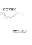
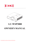
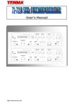
Table of contents Safety Information ---------------------------------------------------------------------- 1 Chapter 1 Introduction --------------------------------------------------------------- 3 1.1 The Acute DS-1000 series digital storage oscilloscope (DSO) -------------------------- 4 1.2 Packing list -------------------------------------------------------------------------------------- 5 1.3 Specifications ----------------------------------------------------------------------------------- 6 1.4 System Requirement --------------------------------------------------------------------------10 Chapter 2 Installation -------------------------------------------------------------- 11 2.1 Installation Procedures ------------------------------------------------------------------------12 2.2 Quick Start: (Calibration) --------------------------------------------------------------------21 Chapter 3 Operations --------------------------------------------------------------- 23 3.1 Window -----------------------------------------------------------------------------------------24 3.2 Operation ---------------------------------------------------------------------------------------25 3.2.1 Channel Switch Button ------------------------------------------------------------------------------------- 25 3.2.2 VOLTS/DIV Knob ------------------------------------------------------------------------------------------ 26 3.2.3 SEC/DIV Knob ---------------------------------------------------------------------------------------------- 27 3.2.4 Main Function Button -------------------------------------------------------------------------------------- 28 3.2.5 Sub-Function Button --------------------------------------------------------------------------------------- 29 3.2.6 Shortcut - Function Button -------------------------------------------------------------------------------- 30 3.2.7 Panel Switch Button ---------------------------------------------------------------------------------------- 32 3.2.8 Skin Panel ---------------------------------------------------------------------------------------------------- 33 3.2.9 Threshold ----------------------------------------------------------------------------------------------------- 34 3.2.10 Channel ------------------------------------------------------------------------------------------------------- 34 3.2.11 Trigger Position --------------------------------------------------------------------------------------------- 34 3.2.12 Scroll Bar ----------------------------------------------------------------------------------------------------- 35 i Acute Technology Inc. Copyright 2011 3.2.13 Panel Sizing Knob ------------------------------------------------------------------------------------------ 35 Chapter 4 Functionality ------------------------------------------------------------ 36 4.1 Trigger -------------------------------------------------------------------------------------------37 4.2 Display ------------------------------------------------------------------------------------------39 4.3 Cursor -------------------------------------------------------------------------------------------41 4.4 Measurement -----------------------------------------------------------------------------------42 4.5 Utility --------------------------------------------------------------------------------------------43 4.6 Save/Recall -------------------------------------------------------------------------------------50 4.7 Acquire ------------------------------------------------------------------------------------------51 Chapter 5 How to stack more than one DSO ---------------------------------- 52 5.1 How to use DSO stacks -----------------------------------------------------------------------53 5.2 APPENDIX-------------------------------------------------------------------------------------54 5.2.1 Index ---------------------------------------------------------------------------------------------------------- 54 5.2.2 Probe Specification ----------------------------------------------------------------------------------------- 55 ii Acute Technology Inc. Copyright 2011 Safety Information Please review the following safety information to avoid injury and prevent damage to the DS-1000 or any products connected to it. Symbol definitions: This symbol indicates that the manual should be referred to. “WARNING” denotes that, if not correctly performed or adhered to, WARNING could result in injury or loss of life. Do not proceed beyond a warning until the indicated conditions are fully understood and met. “CAUTION” denotes that, if not correctly performed or adhered to, could result in damage to or destruction of DS-1000. Do not proceed CAUTION beyond a caution sign until the indicated conditions are fully understood and met. “NOTE” denotes that refer to the manual, which provides operational NOTE information of which the user should be aware. WARNING Do not operate without cover(s). Do not operate the DS-1000 with any cover(s) removed. This may result in electric shock or fire hazard if any part(s) inside is touched. Use USB2.0 power only The DS-1000 should be powered by the PC’s USB2.0 port. Use only the DS-1000 USB cable to connect to the PC’s USB2.0 port. Do not operate in wet or damp conditions. Do not modify or operate the DS-1000 if there was any suspected damage, have it 1 Acute Technology Inc. Copyright 2011 inspected by qualified service personnel. Connect the Probe Properly Connect the ground lead of the probe to earth ground only. Do not connect the ground lead to an elevated voltage. Do not connect or disconnect probes or test leads while they are probed to a voltage source. Prohibition CAUTION Observe ALL Terminal Ratings. To avoid fire or shock hazard, observe all ratings and markings on the product. Consult the product manual for further ratings information before making connections to the product. Do not operate in the following installation location y In direct sunlight. y In extremely hot and/or humidity areas. y With always mechanical vibrations. y Around areas with strong lines of magnetic forces or impulse voltage. Remove the USB cable from the DS-1000 if it is not being used. The temparature of the DS-1000 increases after being used for a while. 2 Acute Technology Inc. Copyright 2011 Chapter 1 Introduction 3 Acute Technology Inc. Copyright 2011 1.1 The Acute DS-1000 series digital storage oscilloscope (DSO) The DS-1000 series is a PC-based digital storage oscilloscope. It has many functions like those of the stand-alone DSOs, but easy to carry (USB2.0 power, no adapter needed) 4 Acute Technology Inc. Copyright 2011 1.2 Packing list Contents The DS-1000 series 1. Pocket-DSO mainframe 1 2. 250MHz probes (1x/10x) 2* 3. Probe accessory pack 2 4. USB A-B cable 1 5. Installation CD 1 6. Quick manual 1 7. Soft case 1 1. 2. 3. 4. 5. * The DS-1002 provides 2 pieces of 100MHz probes (1x/10x). 5 Acute Technology Inc. Copyright 2011 1.3 Specifications Acquisition Real-time sampling, Equivalent sampling, Roll mode, Mode Average, Persistence Input Input Coupling AC, DC, GND Input Impedance 1MΩ±1% // 21pF±5% Max. Input Voltage 42Vpk (DC + AC peak) Vertical Channel 2 (stack up to 3 units to 6 channels.) Resolution 9 bits /channel @ 5mV/DIV- 10V/DIV (8 bits @ 2mV/DIV) Scale range 2mv/DIV to 10V/DIV (as 2-5-10 step) DS-1102, DS-1202, DS-1302: DC to 200MHz Bandwidth DS-1002: DC to 100MHz BW Limit Approx. 20MHz Range 8 divisions Offset range ±4 divisions Offset increments 0.1 division DC accuracy ±3% Hotizontal DS-1102, DS-1202, DS-1302 200MS/s @ 1Ch Real-time sampling 100MS/s @2Ch(Single Shot) Sampling Rate Equivalent sampling 5GS/s (Repetitive) DS-1002 6 Acute Technology Inc. Copyright 2011 100MS/s @ 1Ch Real-time sampling 50MS/s @2Ch(Single Shot) Equivalent sampling 2.5GS/s (Repetitive) Time scale range 2ns/DIV to 10s/DIV (as 2- 5-10 step) Accuracy 100ppm Range 10 Divisions Delay Trigger Time Resolution DS-1002, DS-1102 320 Divisions DS-1202 2560 Divisions DS-1302 5120 Divisions 200ps DS-1002, 1102: 2k points/channel to 64k points/channel DS-1202: 2k points/channel to 512k points/channel Record Length DS-1302: 2k points/channel to 2M points/channel Roll Mode: 32k points/channel (Log Length = Hard Disk limitation) Trigger Rising, Falling, Delay-Trigger, TV-Trigger (DS-1002 no TV Type trigger) Auto, Normal and Single (with RUN/STOP hardware Mode button on the DSO device) Source CH1, CH2, Ext-Trig Coupling DC, HF rejection Sensitivity 5mV/DIV~10V/DIV=1div, 2mV/DIV=1.5div Trigger range ±4 divisions Level increments 0.1 division 7 Acute Technology Inc. Copyright 2011 Measurement and Processing Special function Auto set, Monitor from Internet (TCP/IP) Vpp, Vmax, Vmin, Vamp, Vtop, Vbase, Vupper, Vmiddle, Measurement Vlower, Vmean, Vrms, Positive overshoot, Negative overshoot, Period, Frequency, Pulse width Cursor Time difference, Voltage difference Math Add, Sub, Multiplication, Division Rectangular, Blackman, Hann, Hamming, Harris, FFT Triangularm,Cosine, Lanczos, Gaussian (Vertical scale: dBm RMS, dbV RMS, Linear RMS) WORD, EXCEL, CSV, TEXT, HTML, Clipboard, Hardcopy, Export Data Preview External Trigger Input/Output EXT-TRIG Input TTL Level Limitation EXT-TRIG 1.6V to 5V, rising/falling edge Acknowledge Level EXT-TRIG “>10ns” and “>0.1 TIME/DIV” Acknowledge Freq. 3.3v plus, 20ns delay after trigger occurring (only for TRIG-OUT DS-1000 stack function) Compensater Output Level Approx. 3.3V Frequency 1kHz ±0.5% Environment Operation 0ɗ to +50ɗ 8 Acute Technology Inc. Copyright 2011 Storage -10ɗ to +60ɗ Physical Interface USB2.0 (USB1.1 compatible) Power USB bus power Dimension (device 135/80/26 mm3 only) Weight (device only) 230 g Accessories DS-1102, 1202, 1302: 250MHz probe (1x/10x) x2 Probes DS-1002: 100MHz probe (1x/10x) x2 Others Installation CD, USB2.0 cable, User manual, Soft case. 9 Acute Technology Inc. Copyright 2011 1.4 System Requirement x Above Intel Pentium-III compatible PC (1 GHz or faster recommended). x PC memory above 256M bytes RAM. x At least 64M bytes available in hard disk. x CD-ROM drive (for installation). x Display specification, 640x480 VGA (or above), 800x600 or 1024x768 recommended. x 101 keyboard, Windows keyboard recommended x 2 or 3 buttons mouse. x USB2.0 port. x Microsoft Windows 98se/ME/NT/2000/XP/Vista/Vista-64/Win7/Wind7-64. 10 Acute Technology Inc. Copyright 2011 Chapter 2 Installation 11 Acute Technology Inc. Copyright 2011 2.1 Installation Procedures 2.1.1 Install the Device Driver for the Windows98se (1) Insert the installation CD and please ignore the hardware wizard if you see it, then connect the DS-1000 with your PC. (2) The Windows OS will find an USB device and enter the hardware wizard (Figure 1). Figure 1 Figure 2 (3) Choose “Search for the best driver for your device. (Recommended)” to find the proper driver automatically (Figure 2). (4) Choose “CD-ROM Drive” and click “Next” (Figure 3). Figure 3 Figure 4 (5) Click “Next” when a driver is found (Figure 4). (6) The hardware wizard needs a Window OS CD-ROM to install the “usbscan” driver if your PC has no such driver. 12 Acute Technology Inc. Copyright 2011 (7) Click “Finish” (Figure 5) after the Windows installs the DSO driver. Figure 5 (8) You will see “Acute USB 2.0 Interface” in the Device Manager (Figure 6). Figure 6 Please check our FAQ at www.acute.com.tw or e-mail us at [email protected] if there is any problem regarding the driver installation. 13 Acute Technology Inc. Copyright 2011 2.1.2 Device Driver Installation for Windows 2000 (1) Insert the installation CD and please ignore the hardware wizard if you see it, then connect the DS-1000 with your PC. (2) The Windows OS will find an USB device and enter the hardware wizard (Figure 1). Figure 1 Figure 2 (3) Choose “Search for a suitable driver for my device (Recommended)” to find the proper driver automatically (Figure 2). (4) Choose “CD-ROM Drive”, and click “Next” (Figure 3). Figure 3 Figure 4 (5) Click “Next” when a driver is found (Figure 4). (6) Click “Finish” (Figure 5) after the Windows installs the DSO driver. (7) You will see the “Acute USB 2.0 Interface” in the Device Manager (Figure 6). Please check our FAQ at www.acute.com.tw or e-mail us at [email protected] if there is any problem regarding the driver installation. 14 Acute Technology Inc. Copyright 2011 Figure 5 Figure 6 15 Acute Technology Inc. Copyright 2011 2.1.3 Device Driver Installation for Windows XP (1) Insert the installation CD and please ignore the hardware wizard if you see it, then connect the DS-1000 with your PC. (2) The Windows OS will find an USB device and enter the hardware wizard (Figure 1)., then choose “yes. This time only”. Figure 1 Figure 2 (3) Choose “Install the software automatically (Recommended)” to find the proper driver automatically (Figure 2). Click “Next”. (4) Click “Next” when a driver is found. Figure 3 Figure 4 (5) You will see the “Acute USB 2.0 Interface” in the Device Manager (Figure 6). Please check our FAQ at www.acute.com.tw or e-mail us at [email protected] if there is any problem regarding the driver installation.. 16 Acute Technology Inc. Copyright 2011 Figure 5 Figure 6 17 Acute Technology Inc. Copyright 2011 2.1.4 Install the driver manually (1) Insert the installation CD and connect the DS-1000 with your PC. Choose “Add Device” in the Control panel (Figure 1). Figure 1 Figure 2 (2) Choose “Intall from a list or specific location (Advanced)” (Figure 2)and click “Next”. (3) Choose “Search for the best briver in these locations” (Figure 3); select the DSO directory and click “Next”. Figure 3 Figure 4 (4) Click “Continue Anyway” (Figure 4) to continue the installation procedure. (5) Click “Finish” (Figure 5) after the DSO driver is installed. You may see the “Acute USB 2.0 Interface” in Device Manager (Figure 6).. 18 Acute Technology Inc. Copyright 2011 Figure 5 Figure 6 You will see the “Acute USB 2.0 Interface” in the Device Manager (Figure 6). Please check our FAQ at www.acute.com.tw or e-mail us at [email protected] if there is any problem regarding the driver installation. 19 Acute Technology Inc. Copyright 2011 2.1.5 Install the DSO software (1) Any latest version DSO software will not change existing environment parameters. (2) Insert the installation CD into your PC. (3) Double click to enter the auto-installation procedure. Please run setup.exe at the CD-ROM root directory if the auto-installation does not work. The DSO software will enter DEMO mode if the DSO is not detected by the PC. (4) You will find the DSO software icon ( ) on the Desktop window or Programs after the installation. (5) If the DOS software shows “DEMO Mode” when the DSO is connected to your PC, please e-mail us at [email protected]. 20 Acute Technology Inc. Copyright 2011 2.2 Quick Start: (Calibration) Please and must calibrate the DSO at the first time.ġ ġ (1) Connect the two probes with DSO’s Channel 1 and Channel 2 BNC Connector. (2) Switch the Probe to “x10”. (3) Connect two probe ground pins with the DS-1000’s ground terminator. (4) Connect two probe tips with the DS-1000’s “Probe Comp. (3.3V)” pin. (5) Run the DSO software. (6) Set the Volt/Div = 2v and the Sec/Div = 500us. (7) If you see the waveforms like the following shapes, please follow step (8). (8) Adjust the trimmer located in the probe’s BNC plug to the following shapes. (9) Switch the Probe to “REF” position. (10) Push the “Utility” button. 21 Acute Technology Inc. Copyright 2011 (11) Push “Calibration” of Function Button. (12) The calibration software will ask you to switch the Probe to”x10”. (13) You can change the time base or vertical division after the calibration to check the result. (14) You need to claibrate the DSO again each time you use a different PC because the calibration information is stored in the PC.ġ 22 Acute Technology Inc. Copyright 2011 Chapter 3 Operations 23 Acute Technology Inc. Copyright 2011 3.1 Window 24 Acute Technology Inc. Copyright 2011 3.2 Operation 3.2.1 Channel Switch Button There are 6 channels, CH1, CH2…, CH6 on the upper right corner of the panel (above screen). When you are operating one DSO, only CH1 and CH2 are available and the rest channel buttons, with gray fonts, are not available like CH3 - CH6 on the left. (CH3, CH4) and (CH5, CH6) can be available if two/three units of DSO were stacked up. CH1, with gray button and black fonts, on the left is available but not activated. Click CH2 button, its functions will be activated and its color turns to blue like the one on the left. Each activated channel button has its own color, which is identical to that of the waveform of the channel. Each time you press the channel button will turn on/off the diplay of the channel. 25 Acute Technology Inc. Copyright 2011 3.2.2 VOLTS/DIV Knob The VOLTS/DIV knob is to change the vertical voltage scale. On the screen’s lower-left corner, a voltage scale for each division is displayed and there are 8 divisions on the screen. For example, if the corner displays “CH1 2.00V”, it means that the voltage scale is 2 Volts for each vertical division and the voltage distance from top to bottom of all 8 divisions on the screen is 16 Volts. There are two small buttons near the VOLTS/DIV knob; one is “-“(zoom out), another is “+” (zoom in). You can click your mouse’s left button (or “-“) or the right button (or “+”) on the VOLTS/DIV knob to increase or decrease the voltage scale. Also, the wheel (if there is) of the mouse can be used to adjust the voltage scale even faster. 26 Acute Technology Inc. Copyright 2011 3.2.3 SEC/DIV Knob The SEC/DIV knob is used to change the time scale. On the upper center mid-top of the screen will display the “M 50us” information. This represents each horizontal division time being set up to 50us. You can move the mouse to the SEC/DIV knob and then click the left or right button of the mouse to increase or decrease the time scale. If your mouse has a wheel you can use the wheel to speedily adjust the time scale. There are two small buttons near the SEC/DIV knob. One is “–”, another is “+”. These two small buttons are used for adjusting the time scale when the mouse has only one button. On the screen’s upper-center corner, a time scale for each division is displayed and there are 10 divisions on the screen. For example, if the corner displays “M 50μs”, it means that the time scale is 50 μs for each horizontal division. There are two small buttons near the SEC/DIV knob; one is “-“(zoom out), another is “+” (zoom in). You can click your mouse’s left button (or “-“) or the right button (or “+”) on the SEC/DIV knob to increase or decrease the time scale. Also, the wheel (if there is) of the mouse can be used to adjust the time scale even faster. 27 Acute Technology Inc. Copyright 2011 3.2.4 Main Function Button There are seven main function buttons: Trigger, Display, Cursor, Measure, Utility, Save/Recall, and Acquire under Full mode screen. When you unplug DSO from your PC and launch the DSO AP, the program automatically changes to Demo mode and the Acquire button becomes the Demo button. If you still want to use the Acquire function under Demo mode, please switch the DSO AP to Skin mode from full mode, and then you can find Acquire function under the pull-down function menu on upper right corner. 28 Acute Technology Inc. Copyright 2011 3.2.5 Sub-Function Button There are ten sub-function buttons, which work for the seven main function buttons. Nevertheless, not all sub functions are available in each main function. You may trigger each sub function by clicking the left or right button of the mouse. For example, click the right button of the mouse under sub function (“x1”, “x10”, “x100”) for probe. This sub function will be activated. Click the right button under the same sub function; it activates (“x100”, “x10” or “x1”). 29 Acute Technology Inc. Copyright 2011 3.2.6 Shortcut - Function Button (1) RUN/STOP Button RUN/STOP button runs or stops the signal acquisition process. DSO also has a hot key RUN/STOP button, which does the same function, on its mainframe side. (2) Auto Set DSO will automatically adjust its Volt, Time, and Trigger (parameters) for the tested signals to display their waveform. Nevertheless, it could take a long time for DSO to do so due to big difference between parameters of DSO and those of tested signals. Hence, “AUTOSET” button is used to adjust Volt, Time, and Trigger of DSO for tested signals and display the signals’ waveform more quickly. “AUTOSET” button, when pushed, will find the parameters of the channel being activated. For example, if the “Channel Switch” button is on CH1, then, the Volt, Time, and Trigger of CH1 signals will be benchmark parameters for “AUTOSET” function. (3) Force Trigger When TRIGGER is in Normal /or Single Shot mode and the signal not be triggered; “FORCE TRIGGER” button is used to force DSO0 to trigger the signal. 30 Acute Technology Inc. Copyright 2011 (4) Set to 50% Click the “Set to 50%” button will set the DSO trigger threshold to the average voltage of the signal’s Vpp. (5) HardCopy. Click the “HardCopy” button to print the waveform on your PC’s window. You can press “Utility” ɦ “export” to preview the waveform. 31 Acute Technology Inc. Copyright 2011 3.2.7 Panel Switch Button There are 2 display modes for DSO AP panel; one is full panel, with function buttons on the right of the panel, the other is skin panel, with function buttons hidden. “Panel Switch” button is used to switch DSO AP from full panel to skin panel or vice versa. There are some different operations for these 2 panels. 32 Acute Technology Inc. Copyright 2011 3.2.8 Skin Panel In skin panel, main function buttons are hidden; but you can find those main functions and sub functions in the pull-down menu on the upper right panel. 33 Acute Technology Inc. Copyright 2011 3.2.9 Threshold Threshold is an arrow sign on the right of the panel. When you push the mouse’s left button on the arrow and move, there will be a horizontal dashed line moves accordingly. That is how you adjust the threshold, and the threshold information shows on the lower right of the panel. 3.2.10 Channel Channels are shown on the left of the panel. Each channel has its own tag. You can move any channel’s tag to adjust the channel’s threshold. 3.2.11 Trigger Position Trigger is a red arrow sign on top of the panel. You can drag the trigger to adjust the trigger time. 34 Acute Technology Inc. Copyright 2011 3.2.12 Scroll Bar Scroll bar is a light blue line under the panel. You can see waveform in different time by moving the scroll bar. Double click the left button of the mouse on the scroll bar; then, the scroll bar will move to the middle (50%) of the time 3.2.13 Panel Sizing Knob Panel size knob is on the lower right of the panel. You can drag the knob to adjust the size of the panel. 35 Acute Technology Inc. Copyright 2011 Chapter 4 Functionality 36 Acute Technology Inc. Copyright 2011 4.1 Trigger (1) Edge/Video Trigger has two types: one is Edge; the other is Video. Common signals (non Video signals) can be triggered if they were upward or downward to the Edge. Video signals must be switched to video type; the signals can be NTSCˣPALˣor SECAM. Sub functions change between Edge and Video. (2) Slope Slope is to adjust the Edge. (3) Source Source is to choose a channel’s signals between/among channels to be the trigger. (4) Mode Trigger has 3 modes: Auto, Normal, and Single Shot. Under “Auto”, when the grid of Sec/Div is over 200ms, DS-1000 automatically turns to “Roll Mode”. (5) Memory Depth Under single shot mode, you can adjust memory depth to 2000ˣ4000ˣ8000ˣ16000ˣ 32000 or 64000(DS-1002,DS1102)/512000(DS-1202)/2048000(DS-1302) (6) Video Trigger On “Video Trigger On” sets the trigger to One Field, Odd Field, Even Field, or a Scan Line. It provides Video Scan Line Setting for DS-1202, DS-1302. 37 Acute Technology Inc. Copyright 2011 Steps: a. You can choose the numbers of the scan line. b. Right click the mouse and you will see a dialog box to choose the video type, horizontal frequency or sacn line. c. Video Type: MTSC, PAL or SECAM. d. Horizontal Freq.: Adjust according to the tested signal e. Identify: Click Identity to automatically identify the video type and horizontal frequency of the tested signal. f. Click “Cursor” button and set the Horizontal Unit as IRE will make the video measurement easier. (7) Launch Setting Launch Setting is a sub function under Trigger; it is to launch an external execution file when trigger(s) is activated. Under “Trigger”, click “Trigger Launch Setting” and “Enable” to enable this sub function. There are two options for launch setting; “One Time”, or “Always”. “One Time” means an external execution file will be launched but only one time when the first trigger is activated. “Always” means an external file will be launched every time whenever trigger(s) is activated. Nevertheless, “Always” could result in computer crashed because too many launched external files will take too much memory resources from your PC. 38 Acute Technology Inc. Copyright 2011 4.2 Display (1) Display Turn on/off the display of the channel. (2) Coupling AC, DC or GND. (3) Invert Invert the waveform. (4) Probe The selected multiples (current, x2000, x1000, 200, x100, x10 or x1) must be identical with that of the probe. (5) Bandwidth If the Bandwidth limit (20MHz) is selected, then the signal higher than 20MHz will be filtered. (6) Math “A+B”, “A-B”, “B-A”, “AxB” or “A/B”are mathematical results the values of CH1 and CH2. “X-Y” is the “Lissajous Figure” where CH1 is the time axis and CH2 is the voltage axis. (7) FFT It can transform the selected channel into FFT. (8) FFT Scale The FFT Scale has three modes: Linear RMS, dbV RMS, dBm Rms. (9) FFT Window The FFT window includes “Triangular”, “Cosine”, “Lanczos”, “Gaussian”, “Rectangular”, “Blackman”, “Hann”, “Hamming” and “Harris”. 39 Acute Technology Inc. Copyright 2011 40 Acute Technology Inc. Copyright 2011 4.3 Cursor There are two cursors: Time, and Volt. Time is a vertical line; Volt is a horizontal line. The two lines can be displayed in one yellow solid line (being dragged) and one yellow dashed line, or both not displayed. For example, when you drag Time, Time line turns to a solid line, and Volt line turns to a dashed line, or vice versa. Cursor information, shown on the upper left of the panel, contains two symbols: “@”, and “∆”. “@” means either the distance of time between Cursor and Trigger or the difference of voltage between Cursor and Trigger. “∆” means either the distance of time or voltage between two cursors. Cursors can be moved independently (independent mode) or together with a fixed distance (tracking mode). When cursors are moved out of the panel, click the sub function button “bring all on screen” and all cursors will be brought back to the screen. 41 Acute Technology Inc. Copyright 2011 4.4 Measurement Measurement has 9 items: “Frequency”, “Period”, “Max.”, “Min.”, “High”, “Low”, “Vpp”, “Amplitude”, “Vrms”, “Mean”, “+Duty”, “-Duty”, “+Width”, and “-Width”. Click “Item Select” under Measurement, you will see a pull-down menu with these items. Then, choose the item, the channel, and the position of measurement display. Measurement display has two sub functions: Data area, and Waveform area. “Add” and “Delete” buttons are used in Data area to add or delete measurement value. “Add Tag” and “Del Tag” buttons are used in waveform area to add or delete measurement value. Vmax烉maximum Vmin烉minimum Vpp烉the peak value Vpp = Vmax – Vmin烊 Vmean烉median Vmean = (Vmax + Vmin) / 2烊 Vlow烉low value Vlow = Vmin + Vpp x 10%烊 Vhigh烉high value Vhigh = Vmin + Vpp x 90%烊 42 Acute Technology Inc. Copyright 2011 4.5 Utility (1) Languages It supports English, Spanish, French, Simplified Chinese or Traditional Chinese. (2) Factory Setting Click the “Factory Setting” button to resume all the setup values to the factory origin. (3) Calibration Click the “Calibration” to claibrate the DSO. (4) Logger “Logger” records (saves) waveform data in your computer’s hard disk; “Logger” has three sub functions: Interval, Every Trigger, and Every Sampling. a. Interval (Auto Mode only) “Interval” saves waveform data in an interval (in tens of milli-seconds at least) that can be defined in edit box and Only works in “Auto” mode. “Interval” logs waveform whatever in trigger-activated or time-out periods. You may only log trigger-activated waveform by clicking “excluding time-out”. b. Every Trigger (Auto/Normal/Single Mode) 43 Acute Technology Inc. Copyright 2011 “Every Trigger” saves waveform data whenever trigger activated in each of “Auto”, “Normal”, or “Single” mode; but not in “Roll” mode though. c. Every Sampling (Roll Mode only) “Every Sampling” Only works in “Roll” mode (when Time/Div >= 200ms) and repeatedly saves waveform captured as long as there is space in the hard disk. d. Quick-Log when press Ctrl-L Hot key for logger. There are two different file types, “*.dsow” and “*.log”, for the above “Logger” functions.“*.dsow” is the same file type as that of Reference waveform format; it works for “Interval” and “Every Trigger”, and can be retrieved from “Save/Recall” function. Since there could be too many “*.dsow” files be retrieved; “Waveform Viewer/Waveform Album”, a powerful and user-friendly viewer program, can be used to browse many “*.dsow” files at the same screen.“*.log” works for “Every Sampling” and can only be retrieved through “Import data” function. (5) Export data “Export data” exports waveform data or setup file (*.set), that contains pre-setup parameters such as Time/Div, Volt/Div, Channel number, and Threshold, etc. The information disclosure sub-function can capture the DSO waveform information and change it to a different style. For example: Print out, preview, word, excel text, clipboard and setup, etc. (6) Import data “Import data” imports waveform data, or setup file (*.set) described in “Export data”. The information disclosure sub-function can capture the DSO waveform information and change it to a different style. For example: Print out, preview, 44 Acute Technology Inc. Copyright 2011 word, excel text and clipboard, etc. (7) TCP/IP You can use the DSO thru a different PC by the TCP/IP function. Click “TCP/IP” to show the dialog box on the right. Type the port number for the “Server” PC and enter the IP address and Port number for the “Client” PC to see the wavform from “Server” PC while the DSO is connected with the “Client” PC. PC.Ease of use: Method 1: a. Server part: ”Start” Æ “Execute” Æ input “cmd.exe /k ipconfig.exe /all”, check IP Address (ex. 192.168.1.68). b. Server part: “DSO Program” Æ “Utility” Æ “TCP/IP”, to choose Server to enter the Port. c. Client part: Run ”Internet Explore”. d. Client part: Input “http://192.168.1.68:81”. 45 Acute Technology Inc. Copyright 2011 (8) Waveform display The waveform display has four modes: “Normal”, “Intensity”, “Bezier”, and “Dot”. “Normal” displays the exact waveform captured by the DSO every time. The Normal mode will display each time the DSO hardware acquires one waveform and displays one identical waveform. “Intensity” The Intensity mode will copy the Intensity characters on the screen and will retain the old waveform on the screen until the new waveform appears. The old waveform will then fade out. The Intensity mode can also be used to choose different degrees of brightness. The Bezier mode only shows the waveform information if it is less than the dot number of the screen. When the waveform changes from the standard wave to a spiked wave, then the Bezier mode it used to change it back to the standard wave. “Dot” displays every single dot separately in order to show the real sampling data. (9) Page Select It shows the rest of sub functions in “Utility”. (10) Product Information It contains information regarding DSO hardware, software, firmware, and production date, etc. The information can be very useful in technical support. (11) Pass/Fail Setting “Pass/Fail”, or called “Go/No Go”, is for auto-test purpose. Pick a reference waveform and set benchmark tolerance range for 46 Acute Technology Inc. Copyright 2011 time, and volt of the waveform to create a waveform “tunnel”. Any source waveform goes through the “tunnel”, within the tolerance range, is “Pass”; otherwise, it is “Fail”. Setting procedure is as below: a. Use “Save/Recall” to show the reference waveform (see “Save/Recall” section). b. Enter “Pass/Fail” dialog box. c. Input benchmark tolerance levels for time, and volt. d. Set action for “Pass”, or “Fail”. Sometimes, too many untrue “Fail” events could happen due to unstable (noised) source waveform. You may use the “Average” function or turns on the 20MHz bandwidth limit to filter the unexpected noise. (12) Hot Key Setting “Hot Key Setting” is for non-engineering users like the production line operators who need to operate DSO for production purpose. In the “Hot-Key Setting” dialogue box, you may create “Hot Key” with function(s) or sub-function(s) in “define” list, or you can delete “Hot Key” be pressing “Escape” key. Nevertheless, please be noted that not any function key can be defined as “Hot Key”. (13) Online Update The DSO supports online update. Let your software is new at anytime. (14) Customize 47 Acute Technology Inc. Copyright 2011 ConfigurationTo setting the DSO’s condition, include “Channel Color”, “Gird Mode”. a. Export Word File Set the background color(white/black) for the exported Word file. b. Channel Color Set the channel color c. Har Copy Setting Set the background color (white/black/auto-adjust) for the printed waveform. d. Auto-Adjust printing color Set the background color (white/black/auto-adjust) for the printed waveform. e. Grid Mode There are three types: Dot line, Solid Line or Hide Grid. f. Sound Effect Beep when the trigger succeeds. g. Measurement Method There are three types: smart method, mean voltage, and threshold voltage. h. Label Name 48 Acute Technology Inc. Copyright 2011 Enter the channel name. i. Always check software updates at startup Check if there is any newer version software for online upgrade. 49 Acute Technology Inc. Copyright 2011 4.6 Save/Recall “Save/Recall” has two functions: One is to save the captured waveform(s) into a file(s) or recall the saved waveform(s) from a file(s); another is to save, recall, or delete the “Setup” keys. You may save as many waveforms into files (see the figure below), but only four (maximum) saved waveforms can be “recalled” to be the reference waveform(s) at the same time. “Save/Recall” can also be used to set up parameters like “Time/Div”, “Volt/Div”, “Ground Offset”, Threshold, or “Focus Channel”, … etc. in the four “Setup” keys as hot keys. There are four “Setup”, each with its own time tag, on the application screen (see the figure on the right top), but 35 more can be set up in “Hot Key Setting”, “Export data”, or “Import data”. An easy way is to set F7, for instance, as the “Save Setup Extension” key in the “Hot Key Setting”, F8 as “Load Setup Extension”, and F9 as “Clear Setup Extension”. Now you can press F7 to save your setup, and there are 35 choices (1, 2, …,9, A, B,…, Z) to store it. Press F8 to load your setup(s) or F9 to clear. 50 Acute Technology Inc. Copyright 2011 4.7 Acquire “Acquire” has four options: Sample, ETS, Average, or Persistence. “Sample” displays the captured waveform accordingly. “ETS” records repeated waveforms and forms them to display a fine shape waveform. If Time/Div setup is > 500ns, the DS-1000 automatically switches to “Sample” because it can display a fine shape waveform with 500ns per grid. “Average” is used for averaging signal noise. With “persistence”, the oscilloscope updates the display with new acquisitions, but does not erase the results of previous acquisitions. 51 Acute Technology Inc. Copyright 2011 Chapter 5 How to stack more than one DSO 52 Acute Technology Inc. Copyright 2011 5.1 How to use DSO stacks You can stack 2/3 sets of the DSOs as a 4/6 channels oscilloscope. Use the stack (MCX-MCX) cable to connect the Trigger Output of the master DSO to the Trigger Input of the second DSO, and the same as the second DS-O and the third to stack and synchronize the DSOs. For instance, stack three DSOs as shown below. The stack dialogue box displays the serial numbers of the stacked DSOs; CH1, CH2 have been assigned to the master DSO, and CH3, CH4/CH5, CH6 to the 2nd/3rd DSO. Limitations in the stack mode: Acquisition Mode “Equivalent Sampling” or “Roll Mode” only available for the master DSO. Time Base Sampling Rate Real-time sampling: the same as an individual unit. Equivalent sampling: only available for the master DSO. Time Base Range 5ns/DIV to 100ms/DIV (as 1-2-5 step) available for all DSOs. 200ms/DIV to 10s/DIV (Roll mode) only available for the master DSO. Trigger Source CH1, CH2, Ex-Trig only available for the master DSO. Jitter +/- 200ps available for the master DSO; +/- 10ns for the slave DS-1000(s). 53 Acute Technology Inc. Copyright 2011 5.2 APPENDIX 5.2.1 Index Auto mode Normal mode The waveform will be refreshed either trigger occurs or time-out. The waveform will be refreshed every time trigger occurs. Single-Shot mode The waveform will be refreshed the first time trigger occurs. Roll mode The waveform will not be refreshed but be rolled if SEC/DIV > 200ms. Vpp Peak to peak voltage. Vrms Root-mean square voltage. TV One Field Trigger the video composite pattern in every field. TV Odd Field Trigger the video composite pattern in the odd field. TV Even Field Trigger the video composite pattern in the even field. TV Scan Line Trigger the video composite pattern at any scan line. 54 Acute Technology Inc. Copyright 2011 5.2.2 Probe Specification Position X1 Attenuation Ratio 1:1 Bandwidth DC to 6MHz Rise Time 58nS Input Resistance 1M Ω Input Capacitance 47pF plus oscilloscope capacitance Position X10 Attenuation Ratio 10:1 Bandwidth DC to 250MHz Rise Time 1.4nS Input Resistance 10M Ω when used with oscilloscope with 1M Ω input. Input Capacitance Approx. 17 pF 55 Acute Technology Inc. Copyright 2011 Digital Storage Oscilloscope Manual Copyright2011 Acute Technology Inc. All Rights Reserved. Acute Technology Inc. www.acute.com.tw Address: 6F-7 #12, Ln. 609, ChongXin Rd. Sec. 5, SanChong Dist. 24159, New Taipei city, Taiwan Tel烉+886-2-2999-3275 Fax烉+886-2-2999-3276 E-mail: [email protected] 56 Acute Technology Inc. Copyright 2011