1
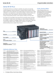
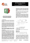
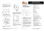
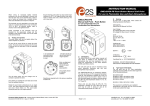
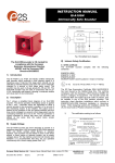
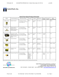
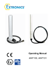
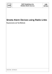
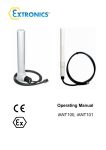
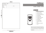
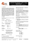
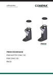
INSTRUCTION MANUAL
IS-mB1 Minialite
Intrinsically Safe Round LED Beacon
This instruction sheet describes installations which conform
to EN60079:Part14:2008 Electrical Installation in Hazardous
Areas. When designing systems for installation outside the
UK, the local Code of Practice should be consulted.
1)
The certification marking is as follows:
IS-mB1 Beacon
II 1G
Ex ia IIC T4 Ga (-40ºC <=Ta<= +60°C)
SIRA 05ATEX2084X
IECEx SIR 06.0045X
Ui = 28V Ii = 660mA Pi = 1.2W
Ci = 0 Li = 0
0518
Year / Serial No. 09 / 1MBR000001
WARNING: TO AVOID A POSSIBLE ELECT ROSTATIC
CHARGE ONLY CLEAN W ITH A DAMP CLOTH
e 2S
european safety systems ltd.
The IS-mB1 beacon is CE marked for
compliance with the European Explosive
Atmospheres Directive 94/9/EC and the
European EMC Directive 89/336/EEC
1. INTRODUCTION
The IS-mB1 is an ATEX and IECEx certified intrinsically safe
beacon which will produce a visual warning in a hazardous
area. Red, Amber, Green and Blue output models are
available.
2)
3)
4)
2. DESCRIPTION
The device will start to flash when power is applied to
terminals + and -. The beacon has two flash rates one double
flash per second and two double flashes per second. The
flash rate is selected by setting an internal pin header. The
unit is factory set to produce two double flashes per second.
3. SUPPLY VOLTAGE
The IS-mB1 beacon has been designed to operate in a
hazardous area via 28V 300 ohm ATEX and IECEx certified
Zener Barriers or Galvanic Isolators. The beacon may be
tested or used in safe areas without a Zener Barrier or
Galvanic Isolator, but at supply voltages above 16V the
internal current limit will function and the brightness may be
reduced. The beacon should not be continuously operated
without a barrier or isolator with a supply voltage greater than
16V.
4. INTRINSIC SAFETY CERTIFICATION
4.1 ATEX certificate
The IS-mB1 beacon complies with the following standards:EN60079-0:2006
EN60079-11:2007
EN60079-26:2007
IEC60079-0:2007 (used for guidance in respect of marking)
II 1G
Ex ia IIC T4 Ga (-40ºC <= Ta <= +60ºC)
The EC-Type Examination Certificate SIRA 04ATEX2084X
has been issued by the Notified Body Sira. This confirms
compliance with the European ATEX Directive 94/9/EC for
Group II, Category 1G equipment. The beacon carries the
Community Mark and subject to local codes of practice, may
be installed in any of the EEA member countries.
5)
6)
7)
8)
London W3 7QH UK
www.e2s.com
The equipment may be used in zones 0, 1 and 2
with flammable gases and vapours with apparatus
groups IIA, IIB & IIC and with temperature classes
T1, T2, T3 and T4.
The equipment is only certified for use in ambient
temperatures in the range -40oC to +60oC and
should not be used outside this range.
The certificate number has an ‘X’ suffix, which
indicates that the certificate contains one of more
special conditions for safe use. Those installing or
inspecting the equipment should refer to this section
of the certificate.
The equipment has not been assessed as a safetyrelated device (as referred to by Directive 94/9/EC
Annex II, clause 1.5).
Installation of this equipment shall be carried out by
suitably-trained personnel in accordance with the
applicable code of practice.
Repair of this equipment shall only be carried out by
the manufacturer or in accordance with the
applicable code of practice.
The certification of this equipment relies on the
following materials used in its construction:
Enclosure:
Lens:
ABS Plastic
Polycarbonate
If the equipment is likely to come into contact with
aggressive substances, then it is the responsibility of
the user to take suitable precautions that prevent it
from being adversely affected, thus ensuring that the
type of protection is not compromised.
“Aggressive substances” - e.g. acidic liquids or
gases that may attack metals, or solvents that may
affect polymeric materials.
“Suitable precautions” - e.g. regular checks as part
of routine inspections or establishing from the
material’s data sheet that it is resistant to specific
chemicals.
_______________________________________________________________________________________________________________________________
European Safety Systems Ltd. Impress House, Mansell Road, Acton, London W3 7QH
[email protected]
Tel: +44 (0)20 8743 8880
www.e2s.com
Fax: +44 (0)20 8740 4200
Document No. IS 5002
Issue E
27-11-09
Sheet 1 of 4
SPECIAL CONDITIONS FOR SAFE USE (as stated in the
EC Type Examination Certificate SIRA 05ATEX2084X)
connection of beacons will significantly reduce the brightness
of each device.
Conditions for IS-mBl Beacon
The maximum permitted cable parameters defined by the
barrier or isolator certificate must not be exceeded.
The equipment has an ingress protection rating of IP65.
However, if it has been supplied without cable entry devices,
then the user shall ensure that the devices that are fitted will
provide an ingress protection that is appropriate to the
environment in which it is installed i.e. IP20 or better. If only
one of the two cable entries are used, then the unused entry
'knockout' shall be left intact or fitted with a blanking device
that ensures ingress protection appropriate to the
environment in which it is installed i.e. IP20 or better.
4.2 Zones, Gas Groups and T Rating
The IS-mB1 LED beacon has been certified Ex ia IIC T4 Ga.
When connected to an approved system it may be installed
in:
Zone 0
explosive gas air mixture
continuously present.
Zone 1
explosive gas air mixture likely to occur in
normal operation.
Zone 2
explosive gas air mixture not likely to occur,
and if it does, it will only exist for a short time.
Be used with gases in groups:
Group
Group
Group
A
B
C
F las h Ra te
5. INSTALLATION
In addition to the certification requirements shown in section
4.2, the environmental conditions must be within the limits
shown on the product specification. The beacon enclosure
provides IP65 protection and is suitable for installation in an
exterior location if an appropriate sealed cable entry is used.
IS-mB1 beacons should only be installed by trained
competent personnel.
5.1 Mounting
The IS-mB1 minialite beacon may be secured to any flat
surface by inserting two mounting screws through the back of
the round base (see figure 2). The enclosure provides IP65
protection and is suitable for installation in exterior locations
provided that the area around the two mounting screws
through the back of the base moulding has been sealed and
that suitable cable glands with the required IP rating have
been used. The lens should be aimed towards the area
where maximum visibility is required.
a. Unscrew the beacon unit security screw and remove
the beacon section from the base by turning it anticlockwise. Ensure that the ‘O’ ring seal remains in
place.
c.
Fit the required number of 20mm cable glands or
conduit entries into the base and connect the field
wiring to the appropriate beacon terminals as shown
in section 6 and Fig 1 of this manual.
d.
Check that the ‘O’ ring seal is correctly located on the
beacon section (see Fig. 1) and insert the beacon
section into the base. Push it fully home and turn it
clockwise to align the mouldings before tightening the
security screw.
4.3 Terminals + and - power supply
Power is supplied to the beacon via terminals + and - which
have maximum input safety parameters of:
Ci = 0
2H z 1 Hz
Fig 1 Location of field terminals and controls.
b. Remove the required 20mm knockout section(s)
depending on system wiring and mount the base to a
flat surface by inserting two screws through the back
of the base.
450ºC
300ºC
200ºC
135ºC
Ui
Ii
Pi
IS-mB1 Beacon
Flash Rate
Header Pins
5.2 Installation procedure
propane
ethylene
hydrogen
Having a temperature classification of:
T1
T2
T3
T4
Input Terminals
+ -
The enclosure is non-conducting and may generate an
ignition-capable level of electrosatic charges under certain
extreme conditions. The user should ensure that the
equipment is not installed in a location where it may be
subjected to external conditions that might cause a buildup of electrostatic charges on non-conducting surfaces,
additionally, cleaning of the equipment should be done
only with a damp cloth.
'O' Ring Seal
=
=
=
28V
660mA
1.2W
Li = 0
IS-mB1 beacons may be powered from ATEX certified Zener
barriers or galvanic isolators certified by an EC Approved
Body which have output parameters equal to or less than
28V, 660mA and 1,2W
Up to three IS-mB1 beacons can be connected in parallel
and be powered from a common barrier or isolator. Parallel
_______________________________________________________________________________________________________________________________
European Safety Systems Ltd. Impress House, Mansell Road, Acton, London W3 7QH
[email protected]
Tel: +44 (0)20 8743 8880
www.e2s.com
Fax: +44 (0)20 8740 4200
Document No. IS 5002
Issue E
27-11-09
Sheet 2 of 4
Hazardous Area
Fit mounting screws
through base
Safe Area
20mm knockouts
IS-mB1
Beac on
28V 1.2W
Pos itive
+
+
Barrier
-
Power
Supply
Diode Return
Barrier
On/Off
0V
Fig 2 Mounting Beacon Base.
Fig 4 Single stage alarm using two channel barrier.
6. ELECTRICAL SYSTEM DESIGN FOR INSTALLATION IN
HAZARDOUS AREAS USING ZENER BARRIERS
If the beacon is controlled by a switch in the positive supply,
or the power supply is being turned on and off, only a single
channel Zener barrier is required as shown in Fig 3. This
circuit may also be used if the beacon is being controlled by a
mechanically activated switch on the hazardous area side of
the barrier. The power supply voltage should be between 20V
and the maximum working voltage of the barrier. The circuit
will continue to work at lower voltages, but the beacon light
output level will be reduced.
If the beacon is being operated from a lower voltage power
supply of say 12V or less, then a 15V 100 ohm barrier can be
used which will improve the beacon light output levels at
lower voltages.
Hazardous Area
The IS-mB1 minialight beacon may be powered by any
galvanic isolator having output parameters within the limits
specified in section 4.3, which has been certified Ex ia by an
EC Notified Body. The beacon may be controlled by turning
the galvanic isolator on and off, or by a mechanically
activated switch on the hazardous area side of the isolator.
Hazardous Area
IS-mB1
Beacon
Safe Area
Galvanic
Isolator
+
+
-
-
On / Off
+
Power
Supply
0V
Safe Area
IS-mB1
Beacon
28V 1.2W
Positive
+
-
+
Barri er
On/Off
Power
Supply
0V
Fig 3 Using a single channel barrier.
If the beacon control switch is in the negative wire and the
power supply 0V is earthed, the circuit shown in Fig 4 may be
used. For simplicity the two barriers may be combined into
one package. The power supply voltage should be between
21V and the maximum working voltage of the 28V barrier.
The circuit will continue to work at lower voltages, but the
beacon brilliance will be reduced.
7. ELECTRICAL SYSTEM DESIGN FOR INSTALLATION IN
HAZARDOUS AREAS USING GALVANIC ISOLATORS.
Galvanic isolators do not require a high integrity earth
connection. For small systems where a high integrity earth is
not already available, the use of galvanic isolators often
reduces the overall installation cost and simplifies design.
Fig 5 Basic circuit for use with a galvanic isolator.
The control arrangement will vary depending upon the
isolator chosen. The galvanic isolator must be able to supply
an output of 30mA at about 16V.
10. CABLE PARAMETERS
The maximum permitted cable parameters are as specified
on the certificate of the Zener barrier or galvanic isolator that
has been selected for the installation. Normally the limits are
not restrictive, but care should be taken not to exceed a
capacitive limit of 83nF for IIC installations when very long
cables are used.
11. BEACON FLASH RATE
The IS-mB1 can be set to two flash rates 1 double flash per
second 1Hz (slow rate) or two double flashes per second 2Hz
fast rate).
The flash rate is selected by the position of the pin header
next to the input terminal block (see fig 1).
12. MAINTENANCE
The beacon should be regularly inspected to ensure that it
has not been damaged. Frequency of inspection depends
upon environmental conditions, but initially we recommend
that this should be done annually.
_______________________________________________________________________________________________________________________________
European Safety Systems Ltd. Impress House, Mansell Road, Acton, London W3 7QH
[email protected]
Tel: +44 (0)20 8743 8880
www.e2s.com
Fax: +44 (0)20 8740 4200
Document No. IS 5002
Issue E
27-11-09
Sheet 3 of 4
No attempt should be made to repair a faulty IS-mB1
beacon. Suspect beacons must be returned to European
Safety Systems Ltd. or to your local agent for repair.
The IS-mB1 beacons are marked with the certification
requirements for the ATEX and IECEx and approvals.
IS-mB1 Beacon
II 1G
13. GUARANTEE
Beacons which fail within the guarantee period should be
returned to European Safety Systems Ltd. or our local agent.
It is helpful if a brief description of the fault symptoms is
provided.
Ex ia IIC T4 Ga (-40ºC <=Ta<= +60°C)
SIRA 05ATEX2084X
IECEx SIR 06.0045X
Ui = 28V Ii = 660mA Pi = 1.2W
Ci = 0 Li = 0
0518
Year / Serial No. 09 / 1MBR000001
WARNING: TO AVOID A POSSIBLE ELECT ROSTATIC
CHARGE ONLY CLEAN W ITH A DAMP CLOTH
e 2S
european safety systems ltd.
14. CUSTOMER COMMENTS
European Safety Systems Ltd. are always pleased to receive
comments from customers about our products and services.
All communications are acknowledged and whenever
possible, suggestions are implemented.
London W3 7QH UK
www.e2s.com
FM Approval
The IS-mB1 Beacon has also been FM Listed.
IECEx Approval
The IS-mB1 Beacon has also been approved to the IECEx
scheme.
The installation requirements for IS-mB1 beacons approved
to the IECEx scheme are the same as the installation
requirements for IS-mB1 beacons approved to the ATEX
directive.
Certificate No.
IECEx SIR 06.0045X
Marking:
Ex ia IIC T4 Ga (Ta = -40ºC to +60ºC)
Standards:
IEC 60079-0:2004 Edition 4
IEC 60079-11:2006 Edition 5
IEC 60079-26:2006 Edition 2
Marking:
IS Class I, Zone 0, AEx ia IIC T4
IS Class I, Division 1, Groups A, B, C, D
See the Control Drawings D 5036 Sheets 1 and 2 for
installation details and entity parameters.
IS-mB1 Beacon
FM
APPROVED
IS Class l, Division 1, Groups A, B, C, D
IS Class I, Zone 0, AEx ia IIC T4 (-40ºC <=Ta<= +60°C)
Control Drawing D 5036 Year / Serial No. 09 / 1MBR000001
WARNINGS: Substitution of components may impair safety
To prevent ignition of flammable or combustible
atmospheres, disconnect power before servicing
TO AVOID A POSSIBLE ELECTROSTATIC
CHARGE ONLY CLEAN WITH A DAMP CLOTH
e 2S european safety systems ltd.
London W3 7QH UK
www.e2s.com
CONDITIONS OF CERTIFICATION (as stated on the IECEx
Certificate of Conformity IECEx SIR 06.0045X)
·
The equipment has an ingress protection rating of
IP65. However, if it has been supplied without a
cable entry device, then the user shall ensure that
the devices that are fitted will provide an ingress
protection that is appropriate to the environment in
which it is installed i.e. IP20 on better. If only one of
the two cable entries are used, then the unused
entry ‘knockout’ shall be left intact or fitted with a
blanking device that ensues ingress protection
appropriate to the environment in which it is installed
i.e. IP20 or better.
·
The enclosure is non-conducting and may generate
an ignition-capable level of electrosatic charges
under certain extreme conditions. The user should
ensure that the equipment is not installed in a
location where it may be subjected to external
conditions that might cause a build-up of
electrostatic charges on non-conducting surfaces,
additionally, cleaning of the equipment should be
done only with a damp cloth.
_______________________________________________________________________________________________________________________________
European Safety Systems Ltd. Impress House, Mansell Road, Acton, London W3 7QH
[email protected]
Tel: +44 (0)20 8743 8880
www.e2s.com
Fax: +44 (0)20 8740 4200
Document No. IS 5002
Issue E
27-11-09
Sheet 4 of 4
EC DECLARATION OF CONFORMITY
Manufacturer:
European Safety Systems Ltd.
Impress House, Mansell Road, Acton
London, W3 7QH, UK
Equipment Type:
IS-mA1, IS-mA2, IS-mA3,
IS-mB1,
IS-mC1,
IS-mA1M
Directive 94/9/EC: Electrical and Mechanical equipment for use in explosive atmospheres (ATEX)
Notified Body for EC type Examination:
Sira Certification Service
Notified Body No.: 0518
Rake Lane, Eccleston, Chester CH4 9JN, UK
EC-type Examination Certificate:
SIRA 05ATEX2084X
Notified Body for Quality Assurance Notification:
Sira Certification Service
Notified Body No.: 0518
Rake Lane, Eccleston, Chester CH4 9JN, UK
Quality Assurance Notification:
SIRA 05 ATEX M342
Provisions fulfilled by the equipment:
II 1 G Ex ia IIC T4 Ga (-40 °C ≤ Ta ≤ +60 °C) or
I M1 Ex ia I Ma (-40 °C ≤ Ta ≤ +60 °C)
Standards applied:
EN 60079-0:2006
IEC 60079-0:2007
EN 60079-11:2007
EN 60079-26:2007
Directive 89/106/EEC: Construction Products Directive (CPD) – IS-mA1 only
Notified Body for EC type Examination:
VdS Schadensverhütung GmbH
Notified Body No.: 0786
Amsterdamer Str 172-174, 50735 Köln, Germany
EC-type Examination Certificate:
0786-CPD-20338
Standards applied:
EN 54-3:2001 / A1:2002 / A2:2006
Directive 2004/108/EC: Electromagnetic Compatibility Directive (EMC)
Standards applied:
EN 61000-6-1:2007
EN 61000-6-2:2005
EN 61000-6-3:2007
EN 61000-6-4:2007
The standards EN 60079-0: 2006 and EN 60079-11:2007 are no longer harmonized. The requirements of these
standards have been checked against the harmonized standards EN 60079-0:2009 and EN 60079-11:2012 and there
were no major technical changes affecting the latest technical knowledge for the products listed above.
On behalf of European Safety Systems Ltd., I declare that, on the date the equipment accompanied by this declaration is
placed on the market, the equipment conforms with all technical and regulatory requirements of the above listed
directives.
Martin Streetz
Quality Assurance Manager
Telephone: +44 (0)20 8743 8880
Facsimile: +44 (0)20 8740 4200
E-mail: [email protected]
www.e2s.com
Date and Place of Issue: London, 04/07/2012
Document No:
DC-011-Issue_C
European Safety Systems Ltd
Company Registration No. 2763350
Registered Office: Impress House
Mansell Road, London, UK, W3 7QH, UK