1
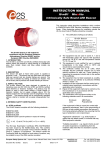
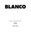
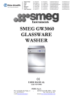
Nº 27 OVENS PYROLYSIS MOD: 2HF-401 B 2HF-401 N 2HF-401 X 2HF-451 B 2HF-451 N 2HF-451 X OCTUBRE 2001 PRESENTATION / INSTALLATION ................................................................................ Carrying hand-holds Feet Identification plate Building-in housing Building-in dimensions / Precautions Fitting to front of housing Single cavity Cavity volume Shelves and fittings Supply / mains terminal strip flap Removable door 3 3 3 4 4 5 6 7 7 8 9 10 OVEN DOOR / EQUIPMENT .......................................................................................... Pyrolysis door locking Pyrolysis door ventilation Door window Door handle Outer window, pyrolysis door Triple glazed pyrolysis door Pyrolysis door Pyrolysis door equipment Holding inner window no. 2, pyrolysis door Pyrolysis door equipment Door hinges Door hinge type Triple glazed pyrolysis door equipment Pyrolysis door seal (removal) Pyrolysis door seal (fitting / composition) 11 11 11 12 12 13 14 14 15 15 16 16 17 17 18 19 COOLING / SAFETY ....................................................................................................... Protection from overheating Air flow (pyrolysis oven) Cooling / Vapour suction Insulation of the cavity Vent Fascia sealing 20 20 21 22 22 23 23 ACCESSIBILITY .............................................................................................................. Oven lighting Component flap Top plate / Back case assembly Fascia operational assembly Glass fascia Heating elements Fan motor 24 24 24 25 25 26 26 27 PYROLYSIS ..................................................................................................................... Principle of pyrolysis Pyrolysis door locking Access to locking mechanism Locking microswitch Oven not operational; door locked 28 28 29 29 30 31 ELECTRONIC PROGRAMMER ..................................................................................... 32 TSE-N 05.01 A. Si. -2- 599 51 17 55 EN PRESENTATION CARRYING HANDHOLDS FEET With these, 3 on the left side and 3 on the right side in contact with the air (between the oven and the wall of the housing), the following can take place: - centring between walls of the housing, circulation of air under the appliance. They prevent: - the sides of the oven from being in contact with the housing walls, the underneath of the oven from being in contact with the housing. TSE-N 05.01 A. Si. -3- 599 51 17 55 EN IDENTIFICATION PLATE LOCATED ON THE RIGHT SIDE OF THE OVEN Information to be entered in the user manual Identification Plate Model BUILT-IN OVEN Serial number Subject number BUILDING-IN HOUSING Oven with pyrolytic cleaning: - Housing closed at the back. Exhaustion of vapour/fumes is exclusively directed to the front of the oven: between the door and fascia. TSE-N 05.01 A. Si. -4- 599 51 17 55 EN BUILDING-IN DIMENSIONS / PRECAUTIONS To prevent abnormal heating, a space of at least 5 mm must separate the frame of the oven from the adjacent panels (kitchen unit doors, etc.). The adjacent walls or their coverings and the adhesive must withstand a temperature of at least 100ºC. COLUMN INSTALLATION INSTALLATION UNDER WORKTOP TSE-N 05.01 A. Si. -5- 599 51 17 55 EN FITTING TO FRONT OF HOUSING The two sleeves are in place on the front of the oven. - The orientation of these is such that (in the case of a unit with 18 mm thick walls) screwing in can be centred perfectly. TSE-N 05.01 A. Si. -6- 599 51 17 55 EN SINGLE CAVITY A) Pressed (non-detachable) side rack shelf supports. B) Non-detachable floor. C) Enamel: Pyrolysis: smooth, black CAVITY VOLUME - Conventional, with pyrolysis: 55 litres - Multi-function, with pyrolysis: 51 litres TSE-N 05.01 A. Si. -7- 599 51 17 55 EN SHELVES AND FITTINGS Dish shelf Depending on the model, the oven can be: Step facing up - delivered with 1 or 2 shelves 1 multi-purpose tray Step facing down - equipped or not equipped with a spit drive. Multi-purpose tray Spit drive The spit is systematically positioned diagonally (even in the non-multi-function ovens) so that larger items can be roasted. forks spit spit holder TSE-N 05.01 A. Si. -8- 599 51 17 55 EN SUPPLY / MAINS TERMINAL STRIP FLAP 3-pole terminal strip 230 V single-phase oven As is the case with all the sheet metal covering, the mains terminal strip flap must be correctly positioned and fastened so that the cooling circuit is formed in perfect conditions. The ovens are equipped with a 1.50 m mains flexible lead (without plug). TSE-N 05.01 A. Si. -9- 599 51 17 55 EN REMOVABLE DOOR 1) Raise the locking lever on the right and left hinges. 2) Close the door again to press against the locking levers. Lift the door up to detach it. IMPORTANT: TSE-N 05.01 A. Si. to prevent consumers from causing after-sales service work, the user manual supplied with the oven does not mention the possibility of detaching the door. This operation is reserved for the after-sales service technicians. - 10 - 599 51 17 55 EN OVEN DOOR / EQUIPMENT PYROLYSIS DOOR LOCKING The catch finger located below the fascia prohibits opening of the door during the pyrolysis cycle. PYROLYSIS DOOR VENTILATION Natural ventilation of the door TSE-N 05.01 A. Si. - 11 - 599 51 17 55 EN DOOR WINDOW 1) Remove the 2 window fastening screws. 2) Separate the window from the inner door to release the lower fastening brackets. 3) Slide the window down to release the top fastening brackets. DOOR HANDLE IMPORTANT: Do not tighten with a levered tool (ratchet handle). Use a straight tool (screwdriver), which will limit tightening torque (a maximum of 30 Nm). Use the screws supplied with the handle (and the washers, depending on the model). TSE-N 05.01 A. Si. - 12 - 599 51 17 55 EN OUTER WINDOW, PYROLYSIS DOOR (WINDOW No. 3) ing sten a f s dle Han screw * = silicone providing the seal between the outer window and the inner door (cannot be applied as part of after-sales service) A= brackets providing for top fastening of the window (these are held by the handle fastening screws) B = brackets providing for lower fastening of the window (cannot be stuck on as part of after-sales service) - under after-sales service, the outer window is supplied with the lower brackets stuck on and the top brackets stuck on, the silicone providing the seal in place. TSE-N 05.01 A. Si. - 13 - 599 51 17 55 EN TRIPLE GLAZED PYROLYSIS DOOR ARRANGEMENT OF WINDOWS OUTSIDE OF THE APPLIANCE OUTER WINDOW No. 3 INNER WINDOW No. 2 INNER WINDOW No. 1 INNER DOOR INSIDE OF THE APPLIANCE (CAVITY) PYROLYSIS DOOR Seal Material: glass braid Core: steel wire - Do not place the joint at the lower part of the door. TSE-N 05.01 A. Si. - 14 - 599 51 17 55 EN PYROLYSIS DOOR EQUIPMENT (INNER WINDOW No. 1) Inner window HOLDING INNER WINDOW No. 2, PYROLYSIS DOOR It is inserted and held. TSE-N 05.01 A. Si. - 15 - 599 51 17 55 EN PYROLYSIS DOOR EQUIPMENT The assembled stainless steel section unit (with window) rests against inner window No. 1. DOOR HINGES These, which are held by two screws at the bottom, are slid under a tab at the top. IMPORTANT: a clip at the top prevents any play. Note: the right and left hinges are identical. TSE-N 05.01 A. Si. - 16 - 599 51 17 55 EN DOOR HINGE TYPE In the case of replacing hinges, make sure that the new hinges have the same identification as the old ones (01, 02, etc.), this identification being identical on the right and left. (The identification 01, 02, corresponds to the strength of the spring, which is matched with the weight of the door). TRIPLE GLAZED PYROLYSIS DOOR EQUIPMENT 1) 2) 3) Outer window: Thickness: 4 mm Type: Decorated clear glass (Intermediate) inner window: Thickness: 3.2 mm Type: Semi-reflective Inner window: Thickness: 3.3 mm Type: Borosilicate TSE-N 05.01 A. Si. - 17 - 599 51 17 55 EN PYROLYSIS DOOR SEAL Remove the old seal. 1) Grip the seal at one corner and pull so that it comes away. - 2) Do not use any tools. Clips which have remained in place between the cavity and frame of the oven front must be pushed back into the heat insulation. - Trying to take them out would risk damaging the enamel of the oven front frame or of the cavity. TSE-N 05.01 A. Si. - 18 - 599 51 17 55 EN PYROLYSIS DOOR SEAL Fitting a new seal. Offer up and then turn ¼ of a turn to grip the core. (3 on the top horizontal portion, 2 on the bottom horizontal portion and 2 on each vertical portion) - The oven front frame and the cavity are connected by 4 fastening points (2 on each vertical section). Take care not to position any clips at these fastening points. 1) Offer up the seal (with the clips) and insert the clips in the spaces provided and then press on the assembly, which will automatically clip on. PYROLYSIS DOOR SEAL COMPOSITION - Core: 1 stainless steel wire (2 mm) - Flexible component: 8 braided stainless steel wires - Covering: Glass braid (10 mm) - Colour: Black - Operating Temperature: 500ºC - Anti-humidity treatment: Yes TSE-N 05.01 A. Si. - 19 - 599 51 17 55 EN COOLING / SAFETY PROTECTION FROM OVERHEATING Cooling motor Thermal protection device In the event of non-operation of the cooling motor and/or in the event of an abnormal temperature rise, a thermal protection device stops the appliance working. The programmer remains working. TSE-N 05.01 A. Si. - 20 - 599 51 17 55 EN AIR FLOW PYROLYSIS OVEN In order for the cooling circuit to operate correctly, it is essential that the appliance be fitted with all its sheet metal covering, mains terminal strip flap, etc. - It is essential for the building-in housing to be completely closed to optimise cooling of the appliance. EDGE OF KITCHEN UNIT - The cooling motor takes in the air contained between the insulated cavity and the covering cases. - Fresh air penetrates between the insulated cavity and the covering cases, after having circulated around the left and right outer sides of the oven and under the appliance, via the inlet holes located at the mains terminal strip, the spit drive motor, etc. - Fresh air is taken in at the front, on the right and left sides and under the appliance. TSE-N 05.01 A. Si. - 21 - 599 51 17 55 EN COOLING / VAPOUR SUCTION The air flow in the exhaust duct creates a depression at the vent, which promotes extraction of fumes/vapour from the cavity. Exhaustion of fumes/vapour is exclusively directed to the front of the oven, between the door and fascia. INSULATION OF THE CAVITY A heat insulating jacket is wrapped round the cavity. A panel of heat insulation provides rear insulation. Material used: - pyrolysis oven: high density glass wool. TSE-N 05.01 A. Si. - 22 - 599 51 17 55 EN VENT The catalytic cartridge is inserted in the vent. IMPORTANT: The vent is angled at the top. It is essential to position it in the direction shown in the drawing (with the low part of the inclined plane facing the front of the oven). Otherwise: - vapour would no longer be drawn out of the cavity - the air flow would enter the cavity. FASCIA SEALING A seal preventing the air flow from turning back into the operational assembly of the fascia, which would be undesirable. TSE-N 05.01 A. Si. - 23 - 599 51 17 55 EN ACCESSIBILITY OVEN LIGHTING Bulb accessible from the cavity (E14 25 W - 300ºC) COMPONENT FLAP - Due to this, it is possible during maintenance to carry out various checking and measuring operations, etc., without having to remove the oven from the housing altogether. - Due to this, components located close to the fascia can be replaced. TSE-N 05.01 A. Si. - 24 - 599 51 17 55 EN TOP PLATE / BACK CASE ASSEMBLY The back case rests against the top plate to prevent any vibration. 3 bottom tabs FASCIA OPERATIONAL ASSEMBLY - the component support plate, - fascia components (programmer, thermostat, etc.) - and the fascia are separated from the frame when the 2 fastening screws have been removed. TSE-N 05.01 A. Si. - 25 - 599 51 17 55 EN GLASS FASCIA - Remove the control knobs, pushbuttons, etc., located on the fascia. - Depending on the model, the 4 stuck-on brackets are visible and accessible when the component flap has been removed. If the 4 brackets are not visible, remove the fascia operational assembly (see previous paragraph). - Push the 4 brackets from the back, one by one, to remove them from the support. - Do not insert any implements between the fascia and support to help you unclip the fascia. There is a risk of your chipping or breaking the glass fascia. - Before clipping the fascia on again, please make sure the brackets have not become deformed (opened out). If necessary, press them with your finger. 4 STUCK-ON BRACKETS HEATING ELEMENTS - The upper heating element (oven roof + grill) is located inside the cavity. - The lower heating element (oven floor) is located under the cavity and is therefore not visible. - The lower heating element (floor) is removed from its housing by simply removing its fastening screw. - It is essential to insert the heating element with the terminals directed upwards. The holding bar will be positioned in the fixing brackets located in the support plate. TSE-N 05.01 A. Si. - 26 - 599 51 17 55 EN FAN MOTOR The fan rotor is held by a nut (to undo this: turn clockwise). 1) Straighten the safety tab. 2) Turn the motor ¼ of a turn to remove it from its support. 3) When a new motor has been fitted (offer the motor up and then turn one quarter of a turn), press the safety tab partially in. This tab is not in contact with the motor. Its function is to confirm that the ¼ of a turn fitting has been carried out correctly and to prevent the motor from becoming detached. TSE-N 05.01 A. Si. - 27 - 599 51 17 55 EN PYROLYSIS PRINCIPLE OF PYROLYSIS A Definition: Pyrolysis consists of bringing the inside of the oven up to a temperature of approximately 500ºC, whereby all the grease and sugar which has dirtied the oven walls can be burned. B Safety: 1) The door is mechanically locked during the pyrolysis operation. In fact, opening the door when the oven is at approximately 500ºC would lead to self-ignition of the grease by supplying oxygen. It is normal for you to see small, brief flames from time to time in the cavity during the pyrolysis cycle. These go out almost instantaneously due to lack of oxygen. 2) A catalyser, located in the oven vent, filters and purifies the products of pyrolysis to prevent carbon monoxide from being released into the kitchen. The role of the catalyser: The catalyser promotes the conversion of carbon monoxide to carbon dioxide* by reaction with the oxygen contained in the ambient air. * carbon dioxide: a colourless gas which is heavier than air and non-toxic. The more the catalyser is heated, the greater the chemical conversion which can take place. The catalytic cartridge is positioned in the fumes/vapour extraction vent. Its proximity to the upper heating elements means that it is heated during cooking. The catalyser is active during cooking. 3) A fan comes into operation automatically and thus lowers the temperatures of the outer walls of the oven to prevent overheating of the building-in kitchen units. 4) The pyrolysis operation can be carried out only under the control of an operating device (timer or programmer). This makes continuous pyrolysis without control of the timer impossible. 5) A temperature limiter automatically interrupts pyrolysis in the event that the temperature permitted is exceeded. TSE-N 05.01 A. Si. - 28 - 599 51 17 55 EN PYROLYSIS DOOR LOCKING Door locked Door unlocked Cam driven by locking motor With this clearance of approximately 6 mm, the oven door can be unlocked manually when there is a technical problem. ACCESS TO LOCKING MECHANISM - Remove the fascia operational assembly to gain access to the front fastening screw. TSE-N 05.01 A. Si. - 29 - 599 51 17 55 EN LOCKING MICROSWITCH Microswitch operated Contact: 1 4 Microswitch inoperative contact: 1 2 Microswitch inoperative contact: 1 2 DOOR UNLOCKED Microswitch operated contact: 1 4 DOOR LOCKED IMPORTANT: the locking motor is special (green plastic) - Check: insert a screwdriver in the square of the motor - TSE-N 05.01 A. Si. it must turn in only one direction (contrary to the spit drive motor). you can only turn it in one direction. - 30 - 599 51 17 55 EN OVEN NOT OPERATIONAL; DOOR LOCKED Removal of appliance from housing to gain access to operational assembly. 1) Pull gently on the door as if to open it. 2) You see the catch finger (silver in colour) between the door and fascia. 3) Lift the catch finger (using a knife blade) and open the door at the same time (the finger rises approximately 6 mm). 4) The 2 screws for fastening into the housing are accessible for removing the oven from it. OVEN NOT OPERATIONAL; DOOR LOCKED Mechanical jamming prevents the catch finger from being lifted (even manually). Remove the door outer window. 1) Remove the 2 lower window fastening screws. 2) At the bottom, move the window away to release the lower fastening brackets. 3) Release from the upper brackets (slid under the inner door) by pulling the window down. 4) The 2 screws for fastening into the housing are accessible for removing the oven from it. TSE-N 05.01 A. Si. - 31 - 599 51 17 55 EN ELECTRONIC PROGRAMMER Warning light showing programme being carried out Warning light showing automatic operation 1st key: setting the time, timer and stopping the sound signal Adjustment knob 2nd key: length of cooking time or of pyrolysis cleaning time 4th key: manual operation 3rd key: end of cooking or of pyrolysis cleaning Setting the programmer time The clock is prepared for showing the hours from 0 to 23 and the minutes from 0 to 59. After connection of your oven to the electricity mains or after a power cut, your programmer displays 0.00 and AUTO, flashing. To set the time: 1. press the 1st and 2nd keys at the same time and 2. select the time by turning the adjustment knob right or left, depending on the time to be reached. Manual operation The oven can be used manually, i.e. without any programming. Before carrying out any operation, make sure that the programmer is in manual use or press the 4th key. Using the timer: hour glass function The timer function is independent from the oven and has no effect on switching the oven on or off. It can only be obtained when the programmer is in manual operation mode. 1. Press the 1st key and TSE-N 05.01 A. Si. - 32 - 599 51 17 55 EN 2. without releasing it, set the time required by turning the adjustment knob (max. time 23 hrs. 59 mins.). 1 pears. When the time set has elapsed, the alarm sounds for approximately 2 minutes and 1 flashes. To interrupt the sound signal, press the 1st key. The timer does not interrupt cooking at the end of the time set. To switch the oven off, move the thermostat to the position and the function selector to position 0. Semi-automatic programming of cooking (Immediate start Automatic stop) 1. Press the 2nd key, without releasing it. 4 pears. 2. With your other hand, turn the knob to obtain the length of cooking time required; AUTO is displayed. 3. Place the function selector and then the thermostat in the positions required. 1 2 3 4 1 2 3 4 1 2 3 4 When the length of cooking time has elapsed, the alarm sounds for approximately two minutes. To interrupt the sound signal, press the 1st key. AUTO flashes and 4 disappears. Go back to manual operation by pressing the 4th key; AUTO disappears. The oven is no longer operating. However, your food continues to cook due to the residual heat. 4. Move the oven controls to the Stop position (thermostat on then the selector on 0). Automatic programming of cooking (Deferred start Automatic stop) 1. Press the 2nd key, without releasing it. 4 appears. 2. With your other hand, turn the knob to obtain the length of cooking time required; AUTO is displayed. 3. Finally, press the 3rd key without releasing it and turn the knob again to set the end of cooking time. 4. Place the function selector and then the thermostat in the positions required. At the end of cooking, the alarm will sound for approximately two minutes. To interrupt the sound signal, press the 1st key. AUTO flashes and 4 disappears. Go back to manual operation by pressing the 4th key; AUTO disappears. The oven is no longer operating. However, your food continues to cook due to the residual heat. 5. Move the oven controls to the Stop position (thermostat on then the selector on 0). TSE-N 05.01 A. Si. - 33 - 599 51 17 55 EN Semi-automatic programming of pyrolysis leaning Immediate start Automatic stop 1. Turn the function selector and then the thermostat to positions 5; P1.30 and AUTO are displayed (pyrolysis taking 1 hour 30 minutes). 5 If you wish to increase the pyrolysis cleaning time (oven very dirty): 2. Press the 2nd key without releasing it and, with your other hand, turn the adjustment knob to increase the pyrolytic cleaning time (maximum time of 3 hours). 1 2 3 4 1 2 3 4 When pyrolysis cleaning has ended, P0.00 and AUTO flash and 4 disappears. 3. Move the two oven controls to the Stop positions (thermostat on and function selector on 0); AUTO disappears. The time is displayed again. It is normal for the oven door to stay locked after the end of the pyrolysis cleaning cycle until the oven has cooled down sufficiently. Automatic programming of pyrolysis cleaning Deferred start Automatic stop 1. Turn the function selector and then the thermostat to positions 5; P1.30 and AUTO are displayed (pyrolysis taking 1 hour 30 minutes). If you wish to increase the pyrolysis cleaning time (oven very dirty): 2. 3. Press the 2nd key without releasing it and, with your other hand, turn the adjustment knob to increase the pyrolytic cleaning time (maximum time of 3 hours). Finally, press the 3rd key without releasing it and turn the knob again to set the end of pyrolytic cleaning time. 4 disappears. 1 2 3 4 4 will be displayed when the cleaning start time has been reached. 4. Move the two oven controls to the Stop positions (thermostat on and function selector on 0); AUTO disappears. The time is displayed again. It is normal for the oven door to stay locked after the end of the pyrolysis cleaning cycle until the oven has cooled down sufficiently. TSE-N 05.01 A. Si. - 34 - 599 51 17 55 EN