1
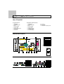
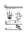
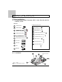
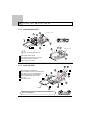
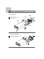
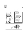
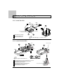
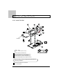
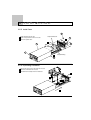
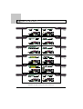
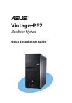
800MHz FSB Pentium 4 System
General Information.................................................................... 2
Item Checklist............................................................................. 2
Mainboard Layout....................................................................... 2
Installation Procedure................................................................. 3
1 Processor/Memory Installation............................................... 3
2 Drive Installation..................................................................... 4
2.1 Corresponding models: Standard, SPDIF, 1 LAN,
1Gb LAN, Mini PCI, 3 RS-232, TV-Out........................... 4
2.1.1 Installation............................................................. 4
2.1.2 Install Standard HDD............................................ 5
2.1.3 Install CD-ROM..................................................... 5
2.1.4 Install Case........................................................... 6
2.1.5 Unpacking Procedure............................................ 6
2.2 Corresponding models: PCMCIA, 3 LAN, DVR-1,
DVR-4, CF reader............................................................ 7
2.2.1 Installation............................................................. 7
2.2.2 Install Slim HDD.................................................... 8
2.2.3 Install Standard HDD............................................ 8
2.2.4 Install CD-ROM..................................................... 9
2.2.5 Install Case........................................................... 10
2.2.6 Unpacking Procedure........................................... 10
Upgrade Models........................................................................... 11
User's Manual
M0180
WARNING
This equipment has been tested and found to comply with the limits for a Class B
digital device, pursuant to Part 15 of the FCC Rules. These limits are designed to
provide reasonable protection against harmful interference when the equipment is
operated in a residential installation. This equipment generates, uses, and can radiate
radio frequency energy and if not installed and used in accordance with the instruction
manual may cause harmful interference to radio communications. However, there is no
guarantee that interference will not occur in a particular installation. If this equipment
does cause harmful interference to radio or television reception, which can be
determined by turning the equipment off and on, the user is encouraged to try to correct
the interference by one or more of the following measures:
* Reorient or relocate the receiving antenna.
* Increase the separation between the equipment and receiver.
* Connect the equipment into an outlet on a circuit different from that to which the
receiver is connected.
* Consult the dealer or an experienced radio TV technician for help.
Notice: The changes or modifications not expressly approved by the party responsible
for compliance could void the user's authority to operate the equivalent.
The system uses entire casing for
1-1
partial heat dissipation, so the
normal operating temperature is
between 40 C ~ 55 C.
1
General Information
Item Checklist
A. System Part List:
1.
2.
3.
4.
5.
6.
7.
8.
B. Barebone System Part List:
Mainboard
Installation Guide
CD
Power Adapter
Power Cable
Plastic Stand (4 pcs)
CPU Cooler
CPU FAN
1.
2.
3.
4.
5.
6.
7.
8.
Mainboard
Installation Guide
CD
Power Adapter
Power Cable
UDMA ATA Cable
CD-ROM Cable
CD-ROM Adapter
9. CPU FAN
10. CPU Cooler
11. Installation Accessory Pack
Mainboard Layout
9
4
3
2
LAN & USB PORTS
J10
1
1394 PORT
VGA
PORT
USB PORT
PARALLEL PORT
EAR PHONE
PORT
1
Intel 865G Chipset
2
Intel 82801EB Chipset
3
I/O Chipset
4
Audio CODEC Chipset
5
Flash EEPROM
6
CPU Socket 478
7
DDR DIMM Sockets
8
IDE Connectors
9
PC104 Plus Connector (option)
10 CPU FAN (FAN 1)
POWER
LED
11 Clear CMOS
COM1
PORT
HDD
LED
PS/2 MOUSE
& KEYBOARD
PORTS
1
IDE1
1
RST
BUTTON
IDE2
1
19V EXT
POWER
PORT
PWON
BUTTON
FAN1
CLEAR CMOS (JP1)
1
LINE OUT
PORT
MIC IN
PORT
1
CLEAR CMOS
Pin 1-2 to Normal
JP1
11
8
1
6
7
5
10
1
Pin 2-3 to Clear
Front Panel Connector
8
7
6
5
4
3
2
Rear Panel Connector
1
1
RJ45 LAN Port
2
Parallel Port
Reset Button
3
PS/2 Mouse Port
4
HDD LED
4
USB Ports
5
Power LED
5
VGA Port
6
Ear Phone Port
6
RS232 COM Port
7
USB Port
7
PS/2 Keyboard Port
8
1394 Port
8
19V Power In
9
LINE-Out Port
1
MIC-In Port
2
Power Button
3
3
9
2
8
7
2
6
1
5
4
Installation Procedure
1 Processor / Memory Installation
Install CPU / Cooler
CPU FAN Screws
CPU Cooler Screws
Rear Panel
4
6
6
Rear Panel
CPU cooler
CPU FAN
Heatsink
Compound
7
3
5
CPU
5
CPU cooler
90
Copper pillaret
2
1
Socket 478
Note: Glue the heatsink compound between the CPU and heatsink.
1 CPU socket level up to 90-degree.
2 Install CPU on CPU socket.
(Match socket pin 1 and CPU cut edge)
3 Install CPU cooler on CPU.
5
Install CPU FAN on CPU Cooler.
6
Tighten CPU FAN with screws to CPU Cooler.
7
Connect CPU FAN connector to mainboard
CPU FAN (FAN1) connector.
4 Tighten CPU cooler with screws into
copper pillaret.
Install Memory
45
2
1 DIMM socket level down to 45-degree.
1
2 Install memory module into the DIMM socket.
45
3
Installation Procedure
2 Drive Installation
2.1 Corresponding models: Standard, SPDIF, 1 LAN, 1Gb LAN, Mini PCI,
3 RS-232, TV-Out
Part List
Installation Accessory Pack
A
CD-ROM Bracket
B
CD-ROM Adapter
C
D
CD-ROM Cable (210mm)
E
F
Printer/COM/VGA Screws (* 6)
G
Front Panel
H
Rear Panel
I
J
K
EMI Sticker (*2)
L
Plastic Stand (*4)
M
Plastic Spacer (* 2)
N
Standard HDD Screws / 3*4 (* 5)
O
CD-ROM Adapter Screws (* 3)
P
CD-ROM Screws (* 5)
Q
Case Screws (* 2)
R
CPU FAN Screws (* 2)
S
CPU Cooler Screws (* 4)
Case
Mainboard
2.1.1 Installation
A
D
HDD Power Connector
C
Note
Note:
Power input DC 19V only
E
J
4
Installation Procedure
2.1.2 Install Standard HDD
D
A
HDD Power Connector
C
2
HDD
1
J
2
Note
N
A
HDD Power Connector
3
Note: Flip the Standard HDD over
1 Install Standard HDD to bracket.
2 Tighten Standard HDD with screws to bracket.
J
3 Install UDMA ATA cable to HDD device.
4 Install to HDD power connector.
2.1.3 Install CD-ROM
O
5
M
1
2
3
4
5
Install CD-ROM to CD-ROM bracket.
Tighten CD-ROM with screws to CD-ROM bracket.
Insert plastic spacer to the CD-ROM adapter.
Install CD-ROM Cable to CD-ROM adapter.
Tighten CD-ROM adapter and CD-ROM
with screws.
1
6 Put on the EMI sticker.
D
4
3
A
5
2
B
2
6
CD-ROM
K
Before next step, you have to complete the install CPU/cooler
and memory installation.
5
P
J
Installation Procedure
2.1.4 Install Case
Q
Complete CPU/cooler
1 Install mainboard into the case.
2 Tighten rear panel with screws on the case.
3 Stick on the plastic stand.
2
F
1
H
I
Complete Memory
3
L
G
2.1.5 Unpacking Procedure
1
1 Remove the screws on the rear panel from the case.
2 Pull out the mainboard from the case.
2
2
6
Installation Procedure
2.2 Corresponding models: PCMCIA, 3 LAN, DVR-1, DVR-4, CF reader
Part List
A
Drive Adapter
B
CD-ROM Bracket
C
CD-ROM Adapter
D
Insulate Pad
E
HDD 40-pin Cable
Installation Accessory Pack
F
EMI Sticker (*2)
N
Plastic Stand (*4)
O
Plastic Spacer (* 2)
P
Slim HDD Screws / 3*6 (* 5)
Q
Standard HDD Screws / 3*4 (* 5)
R
CD-ROM Adapter Screws (* 3)
G
Drive Adapter Screws (* 4)
S
CD-ROM Screws (* 5)
H
Printer/COM/VGA Screws (* 6)
T
Case Screws (* 2)
I
Front Panel
J
U
CPU FAN Screws (* 2)
Rear Panel
V
CPU Cooler Screws (* 4)
K
Case
L
Mainboard
G
2.2.1 Installation
1
M
1
Install and tighten CD-ROM bracket, insulate pad
and the drive adapter with screws.
HDD Power Connector
B
D
A
7
Installation Procedure
2.2.2 Install Slim HDD
HDD
180
2
Note
P
3
1
HDD 40-pin Connector
IDE1/2 Connector
CD-ROM 44-pin Connector
A
1 Install HDD to drive adapter.
B
2 Flip the drive adapter over.
3 Tighten HDD with screws.
Note: Slim HDD height < = 0.35 inch. ( 9 mm)
2.2.3 Install Standard HDD
Pin 1
E
Q
Power Connector
F
E
2
5
3
1
HDD
Pin 1
4
Note
Note: Flip the Standard HDD over
1
2
3
4
5
6
Install CD-ROM 44-pin cable to CD-ROM 44-pin connector.
Install HDD 40-pin cable to HDD 40-pin connector.
Install Standard HDD to bracket.
Tighten Standard HDD with screws to bracket.
Install HDD 40-pin cable to HDD device.
Install to HDD power connector.
8
P
Through middle the cab
ull
Installation Procedure
2.2.4 Install CD-ROM
S
R
O
5
4
3
2
5
1
C
2
F
CD-ROM
7
6
M
Note
L
Note:
Power input DC 19V only
1
2
3
4
5
Install CD-ROM to CD-ROM bracket.
Tighten CD-ROM with screws to CD-ROM bracket.
Insert plastic spacer to the CD-ROM adapter.
Install CD-ROM 44-pin Cable to CD-ROM adapter.
Tighten CD-ROM adapter and CD-ROM with screws.
Before next step, you have to complete the install CPU/cooler
and memory installation.
6
7
Install the drive adapter to the mainboard.
Put on the EMI sticker.
9
Installation Procedure
2.2.5 Install Case
T
Complete CPU/cooler
1 Install mainboard into the case.
2 Tighten rear panel with screws on the case.
3 Stick on the plastic stand.
2
H
1
J
K
I
Complete Memory
3
N
2.2.6 Unpacking Procedure
1 Remove the screws on the rear panel from the case.
2 Pull out the mainboard from the case.
3 Uninstall the drive adapter from the mainboard.
1
3
2
10
Upgrade Models
Standard
SPDIF
addition
SPDIF
PCMCIA
1 LAN
Realtek 8100C
LAN
PCMCIA
3 LAN
1Gb LAN
Realtek 8139C
3*100Mb LAN
Realtek 8110S
LAN
DVR-1
Mini PCI
expanable to
WIFI
1*BT878A
DVR-4
3 RS-232
3 addition
RS-232 ports
4*BT878A
CF reader
TV-Out
NTSC/PAL
output
CF reader
Specifications are subject to change without notice, reference only.
11