1
IQC-2110
RF Signal Recorder
Capture & Playback using the
Tektronix RSA5000 and RSA6000 Series,
Agilent X-Series and Rohde & Schwarz
FSV and FSW Signal Analyzers
OPERATING INSTRUCTIONS
This is a preliminary manual. Specifications, limits, and text are subject to change
without notice. The information within this manual was as complete as possible at
the time of printing. Bird Technologies Group and X-Com Systems are not liable for
errors.
Go to www.xcomsystems.com for the latest revision of this manual.
©
Copyright 2012 by Bird Technologies Group
Instruction Book P/N 920-IQC2110 Rev. P5
Safety Precautions
The following are general safety precautions that are not necessarily related to any specific part or procedure, and do
not necessarily appear elsewhere in this publication. These precautions must be thoroughly understood and apply to
all phases of operation and maintenance.
WARNING
Keep Away From Live Circuits
Operating Personnel must at all times observe general safety precautions. Do not replace components or make
adjustments to the inside of the test equipment with the high voltage supply turned on. To avoid casualties, always
remove power.
WARNING
Do Not Service Or Adjust Alone
Under no circumstances should any person reach into an enclosure for the purpose of service or adjustment of
equipment except in the presence of someone who is capable of rendering aid.
WARNING
Safety Earth Ground
An uninterruptible earth safety ground must be supplied from the main power source to test instruments.
Grounding one conductor of a two conductor power cable is not sufficient protection. Serious injury or death can
occur if this grounding is not properly supplied.
WARNING
Resuscitation
Personnel working with or near high voltages should be familiar with modern methods of resuscitation.
WARNING
Remove Power
Observe general safety precautions. Do not open the instrument with the power on.
Safety Symbols
WARNING
Warning notes call attention to a procedure, which if not correctly performed, could result in personal injury.
CAUTION
Caution notes call attention to a procedure, which if not correctly performed, could result in damage to the
instrument.
The caution symbol appears on the equipment indicating there is important information in the instruction
manual regarding that particular area
Note: Calls attention to supplemental information.
Warning Statements
The following safety warnings appear in the text where there is danger to operating and maintenance personnel, and
are repeated here for emphasis.
WARNING
Heavy load. Do not attempt to lift unaided.
On page 5.
WARNING
Ensure that the correct cords are used. Only cords with of the proper type with the correct power rating should
be used. Otherwise, a potential shock and/or fire hazard may occur.
On page 7.
WARNING
Do not block access to the power cords and connection to the mains. Ensure that the cords are easily accessible in
cases of emergency shutdown and quick disconnection.
On page 7.
WARNING
Never attempt to connect or disconnect RF equipment from the transmission line while RF power is being applied.
Leaking RF energy is a potential health hazard.
On page 8.
WARNING
Ensure all power switches are in the off position before applying AC power.
On page 8 and 14.
WARNING
Do not operate with the panel removed. Doing so could result in personal injury.
On page 25.
WARNING
To avoid personal injury, disconnect the power cord from the AC line before performing any maintenance,
including fuse replacement or changing the line voltage setting.
On page 45.
ii
Caution Statements
The following equipment cautions appear in the text and are repeated here for emphasis.
CAUTION
Always use the protective foam insert when transporting the Data Pack. Otherwise, the drives may become
dislodged and damaged in transit.
On page 5.
CAUTION
Do not block airflow. The air intake vent on the aides and exhaust in the rear of the system must not be
obstructed.
On page 6.
CAUTION
Avoid installing the IQC system near equipment that exhausts or radiates excessive heat (such as power amplifiers
or DC power supplies). Proper ventilation should always be considered as part of the installation location.
On page 6.
CAUTION
Always be certain the 115/230 voltage selector is set to the proper voltage before AC power is applied.
On page 7.
iii
Safety Statements
USAGE
ANY USE OF THIS INSTRUMENT IN A MANNER NOT SPECIFIED BY THE MANUFACTURER
MAY IMPAIR THE INSTRUMENT’S SAFETY PROTECTION.
USO
EL USO DE ESTE INSTRUMENTO DE MANERA NO ESPECIFICADA POR EL FABRICANTE,
PUEDE ANULAR LA PROTECCIÓN DE SEGURIDAD DEL INSTRUMENTO.
BENUTZUNG
WIRD DAS GERÄT AUF ANDERE WEISE VERWENDET ALS VOM HERSTELLER
BESCHRIEBEN, KANN DIE GERÄTESICHERHEIT BEEINTRÄCHTIGT WERDEN.
UTILISATION
TOUTE UTILISATION DE CET INSTRUMENT QUI N’EST PAS EXPLICITEMENT PRÉVUE PAR
LE FABRICANT PEUT ENDOMMAGER LE DISPOSITIF DE PROTECTION DE L’INSTRUMENT.
IMPIEGO
QUALORA QUESTO STRUMENTO VENISSE UTILIZZATO IN MODO DIVERSO DA COME
SPECIFICATO DAL PRODUTTORE LA PROZIONE DI SICUREZZA POTREBBE VENIRNE
COMPROMESSA.
iv
SERVICE
SERVICING INSTRUCTIONS ARE FOR USE BY SERVICE - TRAINED PERSONNEL ONLY. TO
AVOID DANGEROUS ELECTRIC SHOCK, DO NOT PERFORM ANY SERVICING UNLESS
QUALIFIED TO DO SO.
SERVICIO
LAS INSTRUCCIONES DE SERVICIO SON PARA USO EXCLUSIVO DEL PERSONAL DE
SERVICIO CAPACITADO. PARA EVITAR EL PELIGRO DE DESCARGAS ELÉCTRICAS, NO
REALICE NINGÚN SERVICIO A MENOS QUE ESTÉ CAPACITADO PARA HACERIO.
WARTUNG
ANWEISUNGEN FÜR DIE WARTUNG DES GERÄTES GELTEN NUR FÜR GESCHULTES
FACHPERSONAL.
ZUR VERMEIDUNG GEFÄHRLICHE, ELEKTRISCHE SCHOCKS, SIND WARTUNGSARBEITEN
AUSSCHLIEßLICH VON QUALIFIZIERTEM SERVICEPERSONAL DURCHZUFÜHREN.
ENTRENTIEN
L’EMPLOI DES INSTRUCTIONS D’ENTRETIEN DOIT ÊTRE RÉSERVÉ AU PERSONNEL FORMÉ
AUX OPÉRATIONS D’ENTRETIEN. POUR PRÉVENIR UN CHOC ÉLECTRIQUE DANGEREUX,
NE PAS EFFECTUER D’ENTRETIEN SI L’ON N’A PAS ÉTÉ QUALIFIÉ POUR CE FAIRE.
ASSISTENZA TECNICA
LE ISTRUZIONI RELATIVE ALL’ASSISTENZA SONO PREVISTE ESCLUSIVAMENTE PER IL
PERSONALE OPPORTUNAMENTE ADDESTRATO. PER EVITARE PERICOLOSE SCOSSE
ELETTRICHE NON EFFETTUARRE ALCUNA RIPARAZIONE A MENO CHE QUALIFICATI A
FARLA.
v
About This Manual
This manual covers the operating and maintenance instructions for the following models:
IQC-2110
Changes to this Manual
We have made every effort to ensure this manual is accurate. If you discover any errors, or if you have suggestions for
improving this manual, please send your comments to our Solon, Ohio factory. This manual may be periodically
updated. When inquiring about updates to this manual refer to the part number and revision on the title page.
Specifications, limits, and text are subject to change without notice. The information within this manual was as complete as possible at the time of printing. Bird Electronic Corporation is not liable for errors.
Layout
Introduction - Describes the features of the IQC.
Set Up - Describes the set up of the IQC including various configurations and wiring diagrams.
Operation - Lists the parameters, memory usage, and other specifications.
Remote Device Control - Describes how to use the remote functioning of the IQC.
IQC File Format - Describes the details of the file formatting.
Updating the IQC - Describes the details in updating the IQC system.
Maintenance - Procedures for troubleshooting the IQC. Also lists specifications for IQC and its various configurations.
Appendix 1 Capture & Playback Samples - Case studies and trial procedures.
Appendix 2 IQC Disk Sanitization - Describes procedures and guidelines for seecurely erasing information from
the IQC drives..
vi
vii
viii
ix
Table of Contents
Safety Precautions . . . . . . . . . . . . . . . . . . . . . . . . . . . . . . . . . . . . . . . . . . . . . . . . . . . . . . . . . i
Safety Symbols . . . . . . . . . . . . . . . . . . . . . . . . . . . . . . . . . . . . . . . . . . . . . . . . . . . . . . . . . . . . . . . . . . . . . i
Warning Statements . . . . . . . . . . . . . . . . . . . . . . . . . . . . . . . . . . . . . . . . . . . . . . . . . . . . . . . . . . . . . . . . .ii
Caution Statements . . . . . . . . . . . . . . . . . . . . . . . . . . . . . . . . . . . . . . . . . . . . . . . . . . . . . . . . . . . . . . . . iii
Safety Statements . . . . . . . . . . . . . . . . . . . . . . . . . . . . . . . . . . . . . . . . . . . . . . . . . . . . . . . . . . . . . . . . . . iv
About This Manual . . . . . . . . . . . . . . . . . . . . . . . . . . . . . . . . . . . . . . . . . . . . . . . . . . . . . . . . vi
Changes to this Manual . . . . . . . . . . . . . . . . . . . . . . . . . . . . . . . . . . . . . . . . . . . . . . . . . . . . . . . . . . . . . vi
Layout . . . . . . . . . . . . . . . . . . . . . . . . . . . . . . . . . . . . . . . . . . . . . . . . . . . . . . . . . . . . . . . . . . . . . . . . . . . vi
Chapter 1 Introduction. . . . . . . . . . . . . . . . . . . . . . . . . . . . . . . . . . . . . . . . . . . . . . . . . . . . . . 1
Compatible Signal Analyzers . . . . . . . . . . . . . . . . . . . . . . . . . . . . . . . . . . . . . . . . . . . . . . . . . . . . . . . . . 1
Connections . . . . . . . . . . . . . . . . . . . . . . . . . . . . . . . . . . . . . . . . . . . . . . . . . . . . . . . . . . . . . . . . . . . . . . . 2
IQC 2110 . . . . . . . . . . . . . . . . . . . . . . . . . . . . . . . . . . . . . . . . . . . . . . . . . . . . . . . . . . . . . . . . . . . . . . 2
CPG-2110 . . . . . . . . . . . . . . . . . . . . . . . . . . . . . . . . . . . . . . . . . . . . . . . . . . . . . . . . . . . . . . . . . . . . . . 3
DP-HDD-XXX . . . . . . . . . . . . . . . . . . . . . . . . . . . . . . . . . . . . . . . . . . . . . . . . . . . . . . . . . . . . . . . . . . . 3
Chapter 2 System Set Up . . . . . . . . . . . . . . . . . . . . . . . . . . . . . . . . . . . . . . . . . . . . . . . . . . . 5
Unpacking and Inspection . . . . . . . . . . . . . . . . . . . . . . . . . . . . . . . . . . . . . . . . . . . . . . . . . . . . . . . . . . . 5
Unpacking the Data Pack . . . . . . . . . . . . . . . . . . . . . . . . . . . . . . . . . . . . . . . . . . . . . . . . . . . . . . . . . 5
Mounting . . . . . . . . . . . . . . . . . . . . . . . . . . . . . . . . . . . . . . . . . . . . . . . . . . . . . . . . . . . . . . . . . . . . . . . . . 6
Operating on AC Power . . . . . . . . . . . . . . . . . . . . . . . . . . . . . . . . . . . . . . . . . . . . . . . . . . . . . . . . . . . . . 7
Setting up the X-COM IQC-2110 System . . . . . . . . . . . . . . . . . . . . . . . . . . . . . . . . . . . . . . . . . . . . . . . 7
Turning on and Connecting the IQC System . . . . . . . . . . . . . . . . . . . . . . . . . . . . . . . . . . . . . . . . . . 8
Connecting for Capture . . . . . . . . . . . . . . . . . . . . . . . . . . . . . . . . . . . . . . . . . . . . . . . . . . . . . . . . . . 9
Tektronix RSA . . . . . . . . . . . . . . . . . . . . . . . . . . . . . . . . . . . . . . . . . . . . . . . . . . . . . . . . . . . . . . . . . 9
Agilent X-Series . . . . . . . . . . . . . . . . . . . . . . . . . . . . . . . . . . . . . . . . . . . . . . . . . . . . . . . . . . . . . . . 9
Rohde and Schwarz FSV or FSW . . . . . . . . . . . . . . . . . . . . . . . . . . . . . . . . . . . . . . . . . . . . . . . . . . 9
Connecting for Playback . . . . . . . . . . . . . . . . . . . . . . . . . . . . . . . . . . . . . . . . . . . . . . . . . . . . . . . . . 9
Wiring Diagrams . . . . . . . . . . . . . . . . . . . . . . . . . . . . . . . . . . . . . . . . . . . . . . . . . . . . . . . . . . . . . . . . . . 11
IQC System Wiring Diagram, using the Tektronix RSA6000 or 5000A Series . . . . . . . . . . . . . . . 11
IQC System Wiring Diagram, using the Agilent X-Series . . . . . . . . . . . . . . . . . . . . . . . . . . . . . . . 12
IQC System Wiring Diagram, using the Rohde and Schwarz FSV or FSW . . . . . . . . . . . . . . . . . . 13
Setting up the IQC Control Software and Workstation for the First Time . . . . . . . . . . . . . . . . . . . 14
Setting up the Tektronix Real-Time Signal Analyzer . . . . . . . . . . . . . . . . . . . . . . . . . . . . . . . . . . . . . 17
Setting up the Agilent X-Series Signal Analyzer . . . . . . . . . . . . . . . . . . . . . . . . . . . . . . . . . . . . . . . . . 19
Setting up the Rohde and Schwarz FSV Signal Analyzer . . . . . . . . . . . . . . . . . . . . . . . . . . . . . . . . . . 21
Setting up the R&S SMBV Vector Signal Generator . . . . . . . . . . . . . . . . . . . . . . . . . . . . . . . . . . . . . 23
Setting up the Agilent PSG Vector Signal Generator . . . . . . . . . . . . . . . . . . . . . . . . . . . . . . . . . . . . . 24
Chapter 3 Operation. . . . . . . . . . . . . . . . . . . . . . . . . . . . . . . . . . . . . . . . . . . . . . . . . . . . . . . 25
Using the IQC Control Software . . . . . . . . . . . . . . . . . . . . . . . . . . . . . . . . . . . . . . . . . . . . . . . . . . . . . 25
IQC File Listing . . . . . . . . . . . . . . . . . . . . . . . . . . . . . . . . . . . . . . . . . . . . . . . . . . . . . . . . . . . . . . . . 25
Remote Device Settings . . . . . . . . . . . . . . . . . . . . . . . . . . . . . . . . . . . . . . . . . . . . . . . . . . . . . . . . . 25
Connecting an SA or VSG . . . . . . . . . . . . . . . . . . . . . . . . . . . . . . . . . . . . . . . . . . . . . . . . . . . . . . . 25
File Control Functions . . . . . . . . . . . . . . . . . . . . . . . . . . . . . . . . . . . . . . . . . . . . . . . . . . . . . . . . . . 27
Primary Storage List . . . . . . . . . . . . . . . . . . . . . . . . . . . . . . . . . . . . . . . . . . . . . . . . . . . . . . . . . . . 27
Archive Storage List (eSATA) . . . . . . . . . . . . . . . . . . . . . . . . . . . . . . . . . . . . . . . . . . . . . . . . . . . . 27
Check for Orphaned files on Primary Storage Menu . . . . . . . . . . . . . . . . . . . . . . . . . . . . . . . . 28
Settings Menu . . . . . . . . . . . . . . . . . . . . . . . . . . . . . . . . . . . . . . . . . . . . . . . . . . . . . . . . . . . . . . . . 28
Misc Tab Settings . . . . . . . . . . . . . . . . . . . . . . . . . . . . . . . . . . . . . . . . . . . . . . . . . . . . . . . . . . . . 28
Location . . . . . . . . . . . . . . . . . . . . . . . . . . . . . . . . . . . . . . . . . . . . . . . . . . . . . . . . . . . . . . . . . . . . 28
IQ Swap . . . . . . . . . . . . . . . . . . . . . . . . . . . . . . . . . . . . . . . . . . . . . . . . . . . . . . . . . . . . . . . . . . . . 29
x
TCP/IP Tab Settings . . . . . . . . . . . . . . . . . . . . . . . . . . . . . . . . . . . . . . . . . . . . . . . . . . . . . . . . . . . 30
Directories Tab Settings . . . . . . . . . . . . . . . . . . . . . . . . . . . . . . . . . . . . . . . . . . . . . . . . . . . . . . . 30
Help Menu . . . . . . . . . . . . . . . . . . . . . . . . . . . . . . . . . . . . . . . . . . . . . . . . . . . . . . . . . . . . . . . . . . . 30
Capture Data . . . . . . . . . . . . . . . . . . . . . . . . . . . . . . . . . . . . . . . . . . . . . . . . . . . . . . . . . . . . . . . . . . 30
Manual or Timed Capture . . . . . . . . . . . . . . . . . . . . . . . . . . . . . . . . . . . . . . . . . . . . . . . . . . . . . . 31
Max Meter . . . . . . . . . . . . . . . . . . . . . . . . . . . . . . . . . . . . . . . . . . . . . . . . . . . . . . . . . . . . . . . . . . 31
Capture Spans . . . . . . . . . . . . . . . . . . . . . . . . . . . . . . . . . . . . . . . . . . . . . . . . . . . . . . . . . . . . . . . 31
Inserting Markers during Capture . . . . . . . . . . . . . . . . . . . . . . . . . . . . . . . . . . . . . . . . . . . . . . . . . 33
What Is a Marker? . . . . . . . . . . . . . . . . . . . . . . . . . . . . . . . . . . . . . . . . . . . . . . . . . . . . . . . . . . . . 33
How to Insert Markers . . . . . . . . . . . . . . . . . . . . . . . . . . . . . . . . . . . . . . . . . . . . . . . . . . . . . . . . 33
The Usefulness of Marked Data . . . . . . . . . . . . . . . . . . . . . . . . . . . . . . . . . . . . . . . . . . . . . . . . . 33
Playback Control . . . . . . . . . . . . . . . . . . . . . . . . . . . . . . . . . . . . . . . . . . . . . . . . . . . . . . . . . . . . . . . 34
Repeated Playback . . . . . . . . . . . . . . . . . . . . . . . . . . . . . . . . . . . . . . . . . . . . . . . . . . . . . . . . . . . 34
Partial Playback . . . . . . . . . . . . . . . . . . . . . . . . . . . . . . . . . . . . . . . . . . . . . . . . . . . . . . . . . . . . . . 34
Playback with Markers . . . . . . . . . . . . . . . . . . . . . . . . . . . . . . . . . . . . . . . . . . . . . . . . . . . . . . . . 35
File Download Control . . . . . . . . . . . . . . . . . . . . . . . . . . . . . . . . . . . . . . . . . . . . . . . . . . . . . . . . . . 35
Partial File Transfer . . . . . . . . . . . . . . . . . . . . . . . . . . . . . . . . . . . . . . . . . . . . . . . . . . . . . . . . . . . 35
Chapter 4 IQC File Format . . . . . . . . . . . . . . . . . . . . . . . . . . . . . . . . . . . . . . . . . . . . . . . . . 37
Naming Convention . . . . . . . . . . . . . . . . . . . . . . . . . . . . . . . . . . . . . . . . . . . . . . . . . . . . . . . . . . . . . . . 37
Scale Factor . . . . . . . . . . . . . . . . . . . . . . . . . . . . . . . . . . . . . . . . . . . . . . . . . . . . . . . . . . . . . . . . . . . . . . 37
Chapter 5 Updating the IQC . . . . . . . . . . . . . . . . . . . . . . . . . . . . . . . . . . . . . . . . . . . . . . . . 41
Updating the IQCServer Software . . . . . . . . . . . . . . . . . . . . . . . . . . . . . . . . . . . . . . . . . . . . . . . . . . . . 41
Updating the IQC Firmware . . . . . . . . . . . . . . . . . . . . . . . . . . . . . . . . . . . . . . . . . . . . . . . . . . . . . . . . . 43
Chapter 6 Maintenance . . . . . . . . . . . . . . . . . . . . . . . . . . . . . . . . . . . . . . . . . . . . . . . . . . . . 45
Preventive Maintenance . . . . . . . . . . . . . . . . . . . . . . . . . . . . . . . . . . . . . . . . . . . . . . . . . . . . . . . . . . . . 45
Replacing Fuse . . . . . . . . . . . . . . . . . . . . . . . . . . . . . . . . . . . . . . . . . . . . . . . . . . . . . . . . . . . . . . . . . . . . 45
Troubleshooting . . . . . . . . . . . . . . . . . . . . . . . . . . . . . . . . . . . . . . . . . . . . . . . . . . . . . . . . . . . . . . . . . . 45
Capture . . . . . . . . . . . . . . . . . . . . . . . . . . . . . . . . . . . . . . . . . . . . . . . . . . . . . . . . . . . . . . . . . . . . . . 45
Networking . . . . . . . . . . . . . . . . . . . . . . . . . . . . . . . . . . . . . . . . . . . . . . . . . . . . . . . . . . . . . . . . . . . 46
Frequently Asked Questions . . . . . . . . . . . . . . . . . . . . . . . . . . . . . . . . . . . . . . . . . . . . . . . . . . . . . . . . 46
Specifications . . . . . . . . . . . . . . . . . . . . . . . . . . . . . . . . . . . . . . . . . . . . . . . . . . . . . . . . . . . . . . . . . . . . . 46
IQC-2110 . . . . . . . . . . . . . . . . . . . . . . . . . . . . . . . . . . . . . . . . . . . . . . . . . . . . . . . . . . . . . . . . . . . . . 46
CPG-2110 . . . . . . . . . . . . . . . . . . . . . . . . . . . . . . . . . . . . . . . . . . . . . . . . . . . . . . . . . . . . . . . . . . . . . 47
DP-HDD-XXX . . . . . . . . . . . . . . . . . . . . . . . . . . . . . . . . . . . . . . . . . . . . . . . . . . . . . . . . . . . . . . . . . . . 47
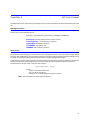
Appendix 1 Capture & Playback Examples . . . . . . . . . . . . . . . . . . . . . . . . . . . . . . . . . . . 49
Capture & Playback of FRS 2-Way Radios with the RSA . . . . . . . . . . . . . . . . . . . . . . . . . . . . . . . . . . 49
Capture & Playback of FM Radio with the RSA . . . . . . . . . . . . . . . . . . . . . . . . . . . . . . . . . . . . . . . . . 50
Appendix 2 IQC Disk Sanitization . . . . . . . . . . . . . . . . . . . . . . . . . . . . . . . . . . . . . . . . . . . 53
Statement of Compliance . . . . . . . . . . . . . . . . . . . . . . . . . . . . . . . . . . . . . . . . . . . . . . . . . . . . . . . . . . 53
Sanitization Procedure . . . . . . . . . . . . . . . . . . . . . . . . . . . . . . . . . . . . . . . . . . . . . . . . . . . . . . . . . . . . . 54
References and standards: . . . . . . . . . . . . . . . . . . . . . . . . . . . . . . . . . . . . . . . . . . . . . . . . . . . . . . 55
Miscellaneous references: . . . . . . . . . . . . . . . . . . . . . . . . . . . . . . . . . . . . . . . . . . . . . . . . . . . . . . . 55
DP-HD-XXX Disk Purging Procedure . . . . . . . . . . . . . . . . . . . . . . . . . . . . . . . . . . . . . . . . . . . . . . . . . . 55
Tools Needed . . . . . . . . . . . . . . . . . . . . . . . . . . . . . . . . . . . . . . . . . . . . . . . . . . . . . . . . . . . . . . . . . 56
Create Bootable Wiping Tool . . . . . . . . . . . . . . . . . . . . . . . . . . . . . . . . . . . . . . . . . . . . . . . . . . . . 56
Bootable USB Flash Drive . . . . . . . . . . . . . . . . . . . . . . . . . . . . . . . . . . . . . . . . . . . . . . . . . . . . . . 56
Bootable CD . . . . . . . . . . . . . . . . . . . . . . . . . . . . . . . . . . . . . . . . . . . . . . . . . . . . . . . . . . . . . . . . . 57
Wipe DP-HDD-XXX using X-COM SA-WS and LSI HBA . . . . . . . . . . . . . . . . . . . . . . . . . . . . . . . . . 61
Limited Warranty
. . . . . . . . . . . . . . . . . . . . . . . . . . . . . . . . . . . . . . . . . . . . . . . . . . . . . . . . 63
xi
xii
Chapter 1
Introduction
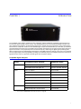
The X-COM IQC-2110 makes it possible for users of Tektronix, Agilent and Rohde and Schwarz Signal Analyzers to
increase their signal storage to hours or days. This capability gives users an unprecedented ability to analyze complex, wideband, long duration, and intermittent wave forms. The IQC-2110 can continuously record and play back
the full 16 bit I and Q data stream from the RSA6000 signal analyzer with bandwidths up to 110 MHz, up to 80 MHz
the Rohde & Schwarz FSW, and up to 40 MHz with the Rohde and Schwarz FSV or Agilent X-Series Signal Analyzers.
Signals are stored in a non-proprietary format to allow analysis by a wide range of digital signal processing tools.
When combined with an X-COM SigAnalyst workstation and X-COM’s Spectro-X software, users have a very powerful
turn-key digital signal processing capability. By adding an X-COM CPG (Continuous Playback Generator) and a Vector
Signal Generator, users can play back recorded signals with exceptional fidelity.
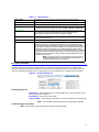
Compatible Signal Analyzers
Vendor
Compatible Signal Analyzer
Supported Spans
Tektronix
All RSA5000 Series with Option 55
10 kHz to 85 MHz, discrete*
All RSA6000 Series with Option 05
10 kHz to 110 MHz, discrete*
PXA - No Options
Up to 10 MHz
PXA Option B25
Up to 25 MHz
PXA Option B40 or Option B1X
Up to 40 MHz
MXA or EXA with Option DP2
Up to 10 MHz
MXA or EXA with Option B25 + Option DP2
Up to 25 MHz
MXA or EXA Option B40 + Option MPB
Up to 40 MHz
FSW with Option B17 and EX-IQ Box Rev 2.0
Up to 40 MHz
FSW with Option B17 and EX-IQ Box
Up to 80 MHz
Agilent
Rohde & Schwarz
* See “Tektronix RSA6000 Discrete Capture Spans” on page 32.
1
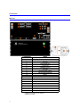
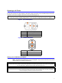
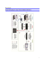
Connections
IQC 2110
Component
Name
1
2
3
4
5
6
7
8
9
10
11
12
13
14
15
16
17
18
19
AC Disconnect
Fuse Drawer
AC Input
Fan Exhaust port
Control LAN
Datapack Connect
Test LAN
I/Q LVDS Digital Capture
I/Q LVDS Digital Playback
IRIG In
TRIG 1 In*
TRIG 1 Out
TRIG 2 In†
TRIG 2 Out
Ref In
Ref Out
eSATA
Power Switch with LED
Removable Operating System Drives (Optional)
* Capture on Trigger Input or markers
† Markers Input only
2
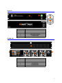
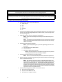
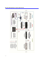
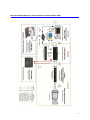
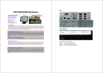
CPG-2110
Component
Name
1
2
3
4
5
Fuse Drawer
AC Input
I/Q LVDS Input
Power Switch with LED
I/Q Analog Output
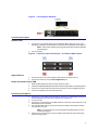
DP-HDD-XXX
Component
Name
1
2
3
4
5
AC Disconnect
AC Input
Mini SAS Connectors
Air Intake Ports
Fan Exhaust Fans
3
4
Chapter 2
System Set Up
Unpacking and Inspection
WARNING
Heavy load. Do not attempt to lift unaided.
1.
2.
3.
Carefully inspect shipping container for signs of damage.
Do one of the following:
• If the shipping container is damaged, do not unpack the unit. Immediately notify
the shipping carrier and X-Com Systems at 703-390-1087.
• If the shipping container is not damaged, unpack the unit.
Note: Save shipping materials for repackaging.
Inspect unit for visual signs of damage.
Note: If there is damage, immediately notify the shipping carrier and X-Com
Systems.
Unpacking the Data Pack
1.
2.
Open the front cover of the Data Pack.
Remove the protective foam insert from the front of the unit.
Note: Save the protective foam insert for future transportation and/or shipment.
CAUTION
Always use the protective foam insert when transporting the Data Pack. Otherwise, the drives may become
dislodged and damaged in transit.
3.
Inspect each drive in the Data Pack by pressing firmly on each individual drive.
Note: Ensure each drive is not loose and is seated properly into the back plane
of the Data Pack. A loose drive will cause the IQC-2110 to not recognize the Data
Pack.
4.
Close the front cover of the Data Pack and lock it into place by tightening the knob
located on the front cover.
Note: To repack the Data Pack, reverse this procedure.
5
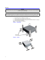
Mounting
CAUTION
Do not block airflow. The air intake vents on the sides and exhaust in the rear of the system must not be obstructed
in order to prevent overheating.
Note: For maximum stability, use eight screws to secure the IQC into the rack.
CAUTION
Avoid installing the IQC system near equipment that exhausts or radiates excessive heat (such as power amplifiers
or DC power supplies). Proper ventilation should always be considered as part of the installation location.
Note: It is recommended that the rack is properly secured to either a wall or the floor.
1. Install the IQC into the equipment or test rack.
2. Secure the IQC to the rack using the mounting screws.
3. Connect proper power supply. See “Setting up the X-COM IQC-2110 System ” on page 7.
4. Connect the IQC to the datapack.
Note: See “Wiring Diagrams” on page 11.
Figure 1 Rack Mount
Mounting
Screws
Figure 2
6
Airflow
Operating on AC Power
For AC power operation, the IQC, Datapack, and CPG are simply connected to an AC receptacle using the line cord
provided. The correct AC voltage is selected via a rear panel switch (Figure 3).
CAUTION
Always be certain the 115/230 voltage selector is set to the proper voltage before AC power is applied.
Figure 3
IQC AC Receptacle
Item No.
1
2
3
Figure 4
Description
AC input voltage selector switch
Fuse holder
AC power cable connector
CPG AC Receptacle
Item No.
1
2
Description
Fuse holder
AC power cable connector
Setting up the X-COM IQC-2110 System
Note: The Datapack and eSATA archive are not hot-swappable – they cannot be connected or disconnected
while the power is on. All other connections can.
WARNING
Ensure that the correct cords are used. Only cords with of the proper type with the correct power rating should
be used. Otherwise, a potential shock and/or fire hazard may occur.
WARNING
Do not block access to the power cords and connection to the mains. Ensure that the cords are easily accessible in
cases of emergency shutdown and quick disconnection.
7
WARNING
Ensure all power switches are in the off position before applying AC power.
WARNING
Never attempt to connect or disconnect RF equipment from the transmission line while RF power is being applied.
Leaking RF energy is a potential health hazard.
Turning on and Connecting the IQC System
1.
Connect power cables to the following devices:
• Signal Analyzer
•
•
•
•
2.
3.
CPG
VSG
Datapack
PC
Connect the IQC Datapack cables (external MiniSAS cables) from the back of the IQC
chassis to the corresponding Datapack slots marked I and Q – either the top or bottom slot (see Figure 5).
Toggle ON the power switch on the back of the Datapack.
Note: Please allow the Datapack to initialize for at least 30 seconds prior to
continuing.
Note: The Datapack is not hot-swappable, therefore it should not be powered
off and the external MiniSAS cables should not be disconnected unless the IQC
Chassis is turned off.
4.
Connect the eStata Archive to the IQC.
Note: Perform the following only if the eSata offloading option has been
purchased.
a.
b.
c.
Connect power to the eSata archive.
Turn the eSata on.
Connect the eSata cables to the IQC.
Note: eSata hot-swapping is not supported, so follow the same protocol
connecting eSata drives as for connecting a Datapack.
5.
Connect the IQC power cable to an AC power outlet.
Note: There is a 15-second timeout before the IQC 2110 can be powered on.
6.
7.
Once the timeout is complete, toggle ON the power switch located in the bottom-right
corner on the back of the IQC.
Note: After turning on the power switch, the IQC takes approximately 8 seconds to initialize – wait before pressing the LED power button located in the topright corner on the front of the unit. The IQC Chassis will take approximately 2
minutes to boot, during which time the green power LED on the front of the unit
will flash. The system will be ready to capture once this green LED has stopped
flashing and is solidly lit. (Likewise, the LED will flash until solidly lit when switching between capture and playback modes.)
Connect the following Ethernet cables to an Ethernet switch.
• The control PCs Ethernet port
•
•
8
The port marked LAN on the IQC
The LAN port of the signal analyzer
Figure 5
Connecting the Datapack
Connecting for Capture
Tektronix RSA
1.
Connect the I and Q LVDS cables from the Digital IQ Out (LVDS) ports to the corresponding I and Q ports marked Capture on the back of the IQC Chassis (see Figure 6).
Note: These will be located on the back panel of the RSA, locate the Digital IQ
Out (LVDS) ports.
2. Turn on the RSA.
Figure 6 LVDS Ports, IQC Chassis Back – for Tektronix RSA Capture
Agilent X-Series
1.
2.
Connect the thinner end of the Agilent LVDS cable to the Capture I port.
Connect the wider end to the X-Series Digital OUT port.
Rohde and Schwarz FSV or FSW
1. Mate the RSX adapter box with the EX-IQ Z-Dok connector.
2. Connect the wide LVDS cables from the RSX I and Q to the IQC Capture I and Q (see Figure 5).
3. Connect the smaller LVDS cable from the EX-IQ IN port to the FSV Digital OUT port.
4. Connect a USB cable from the EX-IQ to the FSV.
Connecting for Playback
1.
2.
3.
4.
5.
Connect the I and Q cables from the back the CPG to the corresponding I and Q ports
marked Playback on the back of the IQC Chassis (see Figure 7).
Turn on the CPG.
Connect the corresponding I and Q BNC cables from the front of the CPG to the I and
Q baseband inputs of the VSG.
Use a 50-Ohm BNC cable to connect the reference oscillator OUT from the VSG to
the clock IN on the IQC.
Note: An internal reference is recommended when playing back, but is not
necessary for capture.
If desired, use this procedure to set up an IRIG B type device for time-referencing
markers during capture:
9
a.
6.
Use one of the following IRIG B type devices:
•
•
•
•
IRIG B120, for CF = IEEE-1344
IRIG B121, for CF = IEEE-1344
IRIG B122
IRIG B123
b. Connect the IRIG output of the device to the IRIG IN on the IQC-2110 using
a 50 Ω BNC cable (see Figure 6).
c. The IQC will automatically synchronize with the IRIG device when it is
receiving a locked signal from the satellites.
Note: The time format for IRIG B types is Coordinated Universal Time (UTC).
If desired, use this procedure to set up an external trigger to begin and end one or multiple captures or to mark data during capture with a timestamp:
Note: Markers are useful as reference points for playback, analysis and partial
downloading of a captured file.
a. Connect an external trigger from an oscilloscope, signal analyzer, or any
other device that provides a rising edge TTL level trigger, to the IQC TRIG 1
IN using a BNC cable (see Figure 7).
Note: If these ports are used to initiate or terminate a capture, it can be done with:
•
•
•
•
A single pulse’s rising and falling edge.
Successive pulse rising or trailing edges.
A rising edge of one pulse and the trailing edge of the next.
A trailing edge of one pulse and the rising edge of the next.
Note: If Trig 1 In is being used for Capture on Trigger, Trig 2 In can be used to
insert markers into the Capture file.
b. Connect a second triggering device to TRIG 2 IN (optional).
c. Set your device(s) to output triggers on desired events and the data will be
marked at those samples (see "Inserting Markers during Capture " on page 33).
Figure 7 Connections for Marking Data, IQC Chassis Back
10
Wiring Diagrams
IQC System Wiring Diagram, using the Tektronix RSA6000 or 5000A Series
11
IQC System Wiring Diagram, using the Agilent X-Series
12
IQC System Wiring Diagram, using the Rohde and Schwarz FSV or FSW
13
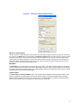
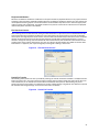
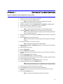
Setting up the IQC Control Software and Workstation for the First Time
WARNING
Ensure all power switches are in the off position before applying AC power.
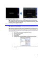
1.
Install the IQC Control Software on a PC or laptop that will be used to control the IQC.
Note: Windows XP, Vista (32 and 64 bit) and 7 (32 and 64 bit) are supported.
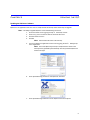
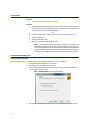
2.
If desired, manually configure the exceptions for three ports in the Windows Firewall
by performing the following procedure:
a. Go to Start > Control Panel > Windows Firewall > Exceptions > Add Port.
b.
Add port number 5843 in the port number field, select UDP, and click OK.
c.
Open ports 5844 and 5845 in the same manner, this time choosing TCP as
the communication type.
Note: Add exceptions for these ports in any antivirus software that may
be running on the control computer.
3.
If desired, customize the IQC network setup.
Note: The IQC’s default IP address is 192.168.2.200. If the IQC does not need to
be changed from the default IP address, skip to XXXXX (e.g.: configured for operation within a LAN of a different subnet).
4.
Configure the IQC to have a static IP address and used on a LAN with other networked devices by determining the following IQC configuration information:
• IP address the IQC should be set to
•
•
•
5.
14
Subnet mask
Gateway IP address
DNS IP address
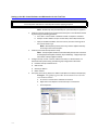
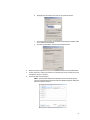
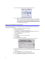
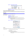
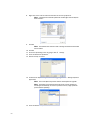
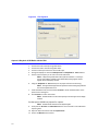
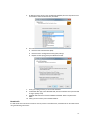
Set up the control PC to obtain an IP address and DNS server address automatically.
Example - The following procedure demonstrates how to do this
on a Windows XP PC:
a. Go to Start > Control Panel > Network Connections.
b.
Right-click on the adapter icon which the IQC is connected to.
c.
Select Properties.
d.
Highlight Internet Protocol and click on the Properties button.
e.
Select both options Obtain an IP address automatically and Obtain DNS
server address automatically.
Click OK, and then OK on the Connection Properties box.
f.
6.
7.
8.
Move the Ethernet cable from the port labeled LAN on the IQC to the port labeled AUX.
Ensure that there is a direct connection from the AUX port to the control PC and not
through any routers or switches.
Launch the IQC Control software.
Note: The IQC Control Software will attempt to connect to the IQC, but fail
once it is launched. Please click Cancel when the dialog box appears stating that
IQC Control failed to connect.
15
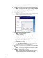
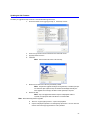
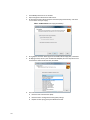
9.
Select Edit > Network > Connect to the IQC Auxiliary Network Port within IQC Control.
Note: A return announcing a successful connection should appear. If not, verify
that there is a direct connection from the control PC to the AUX port and that
DHCP is enabled on the control PC, and then restart IQC Control.
10. Go to Settings> Network> IQC WAN Network Settings within IQC Control.
11. Enter the custom network configuration.
12. Click on Apply, then click Done.
Note: When connecting directly to the IQC, the Gateway and DNS IP addresses
can be set to .1 of the same subnet as the IQC’s IP address.
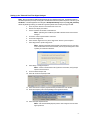
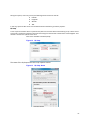
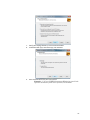
13. Set the IP address of the control PC by doing the following:
a.
b.
c.
d.
e.
f.
Note: The IQC has these defaults:
IP Address: 192.168.2.200
Subnet Mask: 255.255.255.0.
Go to Start > Control Panel > Network Connections.
Right-click on the adapter icon which the IQC is connected to.
Select Properties.
Highlight Internet Protocol and click on the Properties button.
Select Use the following IP address.
Enter the following IP address:
192.168.2.X
Note: Where X = 2 to 254, but not 200 as the IQC and control PC should
not be set to the same IP address.
g. Click OK, and then OK on the Connection Properties box.
14. Move the Ethernet cable back from the port labeled AUX to the port labeled LAN on
the IQC.
Note: The connection may now be made through a switching device, and does
not have to be directly connected.
15. Click on the Connect button in IQC Control software.
Note: The IQC Control Software should now be able to connect to the IQC.
Once connected, a list of the XIQ files on the Datapack should be listed.
16
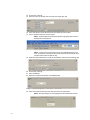
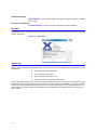
Setting up the Tektronix Real-Time Signal Analyzer
Note: Refer to the Tektronix RSA Operating Manual for more detailed instructions. The following steps are
intended to provide a quick setup. A setup file is included with the RSA to expedite setup time. To access it, go to
File>Recall… in the RSA application and navigate to Desktop>RSA-Settings. Open the file IQC_FRS_CH2.Setup.
Review the following section if you would like to get more familiar with manually setting up the RSA.
1.
2.
3.
Press the power button on the bottom left of the unit.
Wait for the display to initialize.
Set the IP address of the RSA to 192.168.2.32.
Note: Optionally, the IP address of the RSA in Remote Device Control can be
changed.
4.
5.
6.
7.
Go to Edit > Select Capture Mode > Tektronix.
Go to Tools>Alignments.
Select the Run alignments only when “Align Now” button is pressed option.
Select Align Now to perform alignment.
Note: Alignment should be performed after a 20-minute warm-up. The alignment mode should not be set to automatic, else the I/Q streaming data is interrupted by an automatic calibration.
8.
Select Setup > Configure IN/OUT.
Note: In order to stream data to the I/Q external connectors, the I/Q output
option must be turned on.
9. Go to the Other Outputs tab.
10. Select On under the IQ Output field.
11. Select the Center Frequency adjustment box just below the main toolbar.
12. Enter the frequency value corresponding to the signal of interest.
13. Select the Span adjustment box.
Note: Enter the bandwidth frequency that is wide enough to view the entire
signal of interest.
17
14. Go to Setup > Settings.
15. Adjust the value in the Span text box under the Freq & Span tab.
16. Select the reference level adjustment box just below the main toolbar.
17. Set it to the desired level to view the signal.
Note: Signal strength should not go beyond the range of the RSA, as this can
damage internal components.
18. Go to Setup > Amplitude.
Note: In many cases, the attenuation can be set automatically by the instrument. For optimum recording, the attenuation should be set manually to a level
that does not overdrive the A/D circuitry.
19. Adjust the Internal Attenuator manually or automatically under the Internal Settings tab.
20. Go to Setup > Settings.
21. Select the BW tab.
22. Adjust the resolution bandwidth in the RBW textbox.
23. Go to Setup > Configure In/Out.
24. Select the Frequency Reference tab. Select the External radio button.
Note: Recommended for use when playing back into the RSA from the VSG.
18
Setting up the Agilent X-Series Signal Analyzer
Note: Refer to the X-Series Operating Manual for more detailed instructions on signal analyzer operation.
The following represents the minimum steps required to perform capture with the IQC. Button presses and
SCPI commands are provided for each step. The following notation is used:
b_ = Button on front panel
SCPI command (optionally, for remote control)
1.
2.
Press the power button on the bottom-left of the signal analyzer.
Wait for the display to initialize, and the unit to calibrate.
3.
4.
Once the SA is up, log off user Instrument.
Log on:
Name: administrator (no caps)
Password: agilent4u.
Change the IP address to:
192.168.2.220.
5.
6.
7.
Note: Optionally, the IP address of the SA can be changed in Remote Device
Control. See "Remote Device Settings" on page 25.
Go to Edit > Select Capture Mode > Agilent.
Adjust the Center Frequency to a signal of interest.
b_FREQ XYHz
FREQ:CENT XYHz
19
8.
Adjust the Capture Span to include the signal.
b_SPAN XYHz
WAV:DIF:BAND XYHz
Note: A max span of 40 MHz is supported.
9.
Click the Capture button in IQC Control.
Note: The SA will configure to capture mode.
10. Adjust Amplitude, Attenuation, and IF Gain in IQC Control.
11. Update the SA.
Note: To modify the settings on the SA, click Update IQC in capture control to update the capture file settings on the IQC. Alternatively, change the settings in capture control and click Update SA.
20
Setting up the Rohde and Schwarz FSV Signal Analyzer
Note: Refer to the FSV Operating Manual for more detailed instructions on FSV operation. The following
represents the minimum steps required to perform capture with the IQC. Button presses and SCPI commands
are provided for each step. The following notation is used:
b_ = Button on front panel
s_ = Softkey on display
SCPI command (optionally, for remote control)
1.
2.
Press the power button on the bottom-left of the FSV.
Wait for the display to initialize, and the unit to calibrate.
3.
Set the IP address of the FSV to 192.168.2.110.
4.
5.
Note: Optionally, the IP address of the FSV in Remote Device Control can be
changed.
Go to Edit > Select Capture Mode > Rohde & Schwarz.
Adjust the Center Frequency to a signal of interest.
b_FREQ XYHz
SENS:FREQ:CENT XYHz
21
6.
Adjust the Capture Span to include the signal.
b_SPAN XYHz
FREQ:SPAN XYHz
Note: A max span of 40 MHz is supported.
7.
Adjust Pre-Amp, RF Attenuation to suit.
b_AMPL > s_Pre-Amp ON
INP:GAIN:STAT ON
b_AMPL > s_RF Attenuation 0
INP:ATT X
8.
Click the Capture button in IQC Control.
Note: The FSV will configure to capture mode.
22
Note: To further adjust settings on the FSV, press s_Local to enable the touchscreen and modify settings,
then click Update IQC in capture control to update the capture file settings on the IQC. Alternatively, change
the settings in capture control and click Update FSV.
Setting up the R&S SMBV Vector Signal Generator
Note: Refer to the VSG Operating Manual for more detailed instructions. The following represents the minimum steps required to perform RF playback.
Note: A setup file is included with the VSG to help get you started. To access it, press the Setup key on the
VSG front panel and scroll down to Save/Recall… under the System header. (Using a USB mouse makes navigation much easier.) Make sure that Recall appears in the drop-down menu, select the file SMBVSetup, and
click on the Recall button at the bottom of the menu. Review the following section if you would like to know
how to manually set up the VSG.
1.
2.
3.
4.
5.
Press the power button located on the bottom-left of the unit.
Wait for the display to initialize.
Press the Menu button.
Click on I/Q Mod.
Scroll down to and select Analog Wideband I/Q In under the I/Q Mod In header.
6.
Enter the center frequency which corresponds to the original RF frequency captured
by the RSA.
23
7.
Set the desired output level by entering the appropriate dBm value.
8.
Press the Mod Off and RF Off buttons to initiate RF output.
Note: It is important to make sure that the last two blocks – I/Q Mod and RF/A
Mod – are blue (activated), and that RF Off and Mod Off boxes do not appear at
the top of the screen. The first two blocks in the diagram correspond to internal
generation of signals (and are not generally used for IQC playback); the last two
correspond to input and modulation.
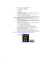
Setting up the Agilent PSG Vector Signal Generator
Refer to the PSG Operating Manual for more detailed instructions. The following represents the minimum steps
required to perform RF playback.
1. Press the power button on the bottom-left of the unit.
2. Wait for the display to initialize.
3. Press the I/Q button on the front panel of the PSG.
4. Set I/Q Mode ON, and I/Q Path to Normal (Mux Source) using the buttons to the
right of the LCD screen to select the proper options.
5. Press the Amplitude button.
6. Turn ALC ON.
7. Press the Mux button on the front panel of the PSG.
8. Select IQ Source.
9. Select Ext 50 Ohm in the next submenu.
10. If the correct settings have been applied, the screen should now look like this:
11. Press the Frequency button on the front panel of the PSG.
12. Enter the center frequency which corresponds to the original RF frequency captured
by the RSA.
13. Press the Amplitude button on the front panel of the PSG.
14. Set the desired output level by entering the appropriate dBm value.
15. Press the Mod On/Off and RF On/Off buttons to initiate RF output.
24
Chapter 3
Operation
WARNING
Do not operate with the panel removed. Doing so could result in personal injury.
Using the IQC Control Software
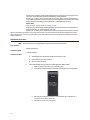
IQC Control is a remote control interface into the operations of the IQC System. This interface controls capture, playback, and file management on the IQC System.
When the IQC Control panel is opened, it connects to the IQC System automatically. A dialog box will appear confirming a successful connection, and the Connect/Disconnect button will read Disconnect
IQC File Listing
Files stored on the Datapack are listed in the IQC Control panel. The file listing includes the file’s name, size, modification date, and protection status. The protection status helps prevent accidental deletion by disabling the Delete
File button. Each file captured through the IQC System contains an IQC file header. The header is used to store information, such as a file’s span, frequency, markers, and protection status. If a file is uploaded that does not contain an
XIQ header, protection and other automated features will not be available. See Figure 8 on page 26.
Remote Device Settings
Remote Device Status (SA or VSG) connections to either an SA or VSG for capture or playback are visible at the bottom of the
IQC Control window. Can be changed by left-clicking on the RDC Settings button. See Detail “B” in Figure 8 on page 26.
Connecting an SA or VSG
1. Select the SA or VSG to be used from the pull down menus.
2. Ensure the device IP address to be used is in the same subnet as the IQC (default is
192.160.2.xxx).
Note: The Remote Device Control window will open. See Detail “B” in Figure 8
on page 26.
3.
Left Click the Connect button.
Note: When the statues bar indicator turns green, the IQC and device are
properly connected and ready to use.
25
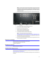
Figure 8
Main IQC Control
Note: Refer to Table 4-1, page 27 for function descriptions.
DETAIL A
Left-Click
DETAIL B
Note: The user must first select the Capture Mode and device via the Remote Device Control window
(Detail “B”) which is opened by left clicking on the RDC Setting button.
26
Table 4-1
Capture Data
List Files on IQC
Playback
Download from IQC
Upload to IQC
Delete File(s)
Connection Status
Device Control Indicators
IQC Functions
Sets the IQC to capture mode and opens the Capture Control Panel.
Refreshes the list of files stored on the IQC.
Sets the IQC to playback mode and opens the Playback Control Panel.
Copies the selected file to the IQC Control client PC. The default location is
C:\IQCFiles; this may be changed by accessing Edit > Settings > Directories.
Copies a file from the client PC to the IQC. A dialog box then prompts the
user to select the I file to be uploaded. The corresponding Q file is
automatically uploaded after the I file completes copying.
Deletes the selected file from the IQC storage. This button is disabled for files
that have been protected.
Provides feedback during connection attempts to the IQC.
On systems with the Remote Device Control option, device control buttons appear
in the lower-right corner of the IQC Control panel for each enabled device. Red
indicates that the device is enabled for use, but is not connected. Gray indicates
that the device is enabled, but is marked as offline. Green indicates that the device
is enabled, connected, and ready for use. To enable or disable a device, click on
RDC settings to bring up the Remote Device Control Window (Detail “B” in Figure 8
on page 26), pull down the Signal Analyzer Menu at the top left, select the desired
SA and press the Connect button. A Series of Status message will appear with the
final status as “Connected”.
Note: At any time, the user may disconnect from, connect to, or
change the Signal Analyzer in use via the RDC Settings button at
the bottom the IQC Control main window.
File Control Functions
The Primary Storage and Archive Storage tabs are only visible above the file listing when an eSATA archive is
attached – otherwise, the primary storage list is always shown. It is possible to protect a file, rename a file, and
check for orphaned files during any use – eSATA options are only available when an eSATA archive is attached.
Figure 9 Primary Storage List
Primary Storage List
Protect File – Sets the protect flag in the file’s header so the Delete File button is disabled when the file is selected.
Rename File – Rename the selected file.
Copy to eSata – Copies both the I and Q files to the attached eSata archive storage unit.
Note: This command is only available when an eSata archive is attached.
Archive Storage List (eSATA)
Note: This command is only available when an eSata archive is attached.
27
Figure 10
Archive Storage List (eSATA)
Right-click on a file in the list to access these functions:
Copy to IQC Primary Storage – Copies both the I and Q files to the Primary storage
(Datapack).
Check for Orphaned files on Primary Storage Menu
The Orphan menu can be accessed under the Edit toolbar menu while connected to the IQC. This feature will list any
file that does not have a matching I or Q file. By selecting a file in the list, you can delete or rename it by right-clicking on the file.
Settings Menu
The Settings menu can be accessed under the Edit toolbar menu.
Misc Tab Settings
Turn Off IQC – Turns off the IQC.
Restart IQC – Restarts the IQC
Config Devices – Sets options for Device Control.
IQC Time –Choose to use an external IRIG-B source or Free Run (IQC local system time)
when making timestamped captures.
Note: All time is displayed in UTC. The IQC system time can be set here according to the system time on the control PC by selecting Set IQC System Clock.
Figure 11
IQC Time
Location
The user may connect the RS-232 output port of an external GPS receiver (user supplied) to the comm port of the PC
running IQC Control.
1. Connect the GPS to the RS-232 port on the IQC.
2. Turn on the GPS.
3. Wait for confirmation of satellite lock.
4. Click on Record GPS Location (Requires GPS).
Note: An ASCII flat file is opened in the same directory with the same file name
as the capture file.
28
During the capture, once every second, the following will be written into this file:
•
•
•
•
Latitude
Longitude
Altitude
TOD
In this way, spectrum data can be time correlated with the GPS file for go-location purposes.
IQ Swap
A user may find a situation where a spectrum they desire to record has been inverted during an up or down conversion process. This feature swaps the I & Q channels coming from the SA used as the RF front end and digitizer. The I
channel is stored in the Q file and vice versa.
Click on the checkbox to enable IQ Swap.
Figure 12
IQ Swap
The status of the IQ Swap can be seen in IQC Capture Control.
Figure 13
IQ Swap Status
29
TCP/IP Tab Settings
IQC IP Address – Sets the IQC IP address. The option to ping an IP address is available
in this control.
Directories Tab Settings
Transfer Directory – Sets the control PC destination for downloaded files.
Help Menu
The Help menu shows all software and firmware versions. Upgrade the software and firmware here. See “Updating
the IQC” on page 41.
Figure 14
About IQC
Capture Data
Starting and stopping captures takes place in the Capture Control Panel. Several settings dictate the filename of the
captured file:
•
•
•
•
12-character user-input description
Center frequency of the signal
Span of the data output from the SA
Timestamp automatically placed by IQC Control
The IQC detects the sampling rate from the SA and automatically sets the span, though the center frequency will not
populate unless the user has enabled device control for the SA (see “Remote Device Settings” on page 25). If no data
is detected, a warning notifies the user. In this case, the user should check that the SA is configured correctly and
that all cables are in place. Settings can be updated either by changing them in capture control, or from the SA, if
RDC is enabled.
30
Figure 15
Tektronix (no RDC) Capture Control
Manual or Timed Capture
Manual capture is the default capture mode. Simply start and stop the capture as desired. To switch to a timed capture, click on the Timed button. This will enable the Seconds to Capture field. The amount of time to capture can be
specified to the tenth of a second. A timed capture may be interrupted at any time, like a manual capture. When
enabling the timed capture capability, a conservative estimate of the amount of memory left in the Datapack for
that span is shown. The amount of time will vary for each span; there will be a greater maximum time for lower
spans, and a lesser maximum time for higher spans.
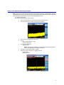
Max Meter
The Max Meter is a visual gauge the of signal strength upon capture. This control reflects the digitizer’s output values in a scale-like format. An output in the lower yellow region is likely too low for a good capture, and an output in
the upper yellow and red regions are likely over-ranging the RSA’s digitizer and clipping the signal. Aim for an output
near 3/4 full-scale, as shown in the above figure.
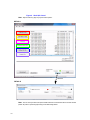
Capture Spans
The Capture Span or Capture Bandwidth refers to the instantaneous bandwidth that will be recorded. With a center
frequency at 400 MHz, a 10 MHz capture span would capture all signals ± 5 MHz from 400 MHz (395 to 405 MHz).
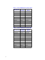
Agilent and Rohde captures can be set to an arbitrary span up to 40 MHz with 1 Hz resolution. Tektronix RSA captures are set to discrete spans according to set sample rates. See table below.
31
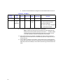
Table 4-2
Tektronix RSA6000 Discrete Capture Spans
RSA Span (Hz)
Data Rate
(Bytes/s)
110,000,000.00
150,000,000
600,000,000
60,000,000.00
75,000,000
300,000,000
40,000,000.00
50,000,000
200,000,000
20,000,000.00
25,000,000
100,000,000
10,000,000.00
12,500,000
50,000,000
5,000,000.00
6,250,000
25,000,000
2,000,000.00
3,125,000
12,500,000
1,000,000.00
1,562,500
6,250,000
500,000.00
781,250
3,125,000
200,000.00
390,625
1,562,500
100,000.00
195312.5
781,250
50,000.00
97656.25
390,625
20,000.00
48828.125
195,313
10,000.00
24414.0625
97656.25
Table 4-3
Tektronix RSA5000 Discrete Capture Spans
RSA Span (Hz)
32
I/Q Sampling
Rate (Sps)
I/Q Sampling
Rate (Sps)
Data Rate
(Bytes/s)
85,000,000.00
150,000,000
600,000,000
40,000,000.00
75,000,000
300,000,000
25,000,000.00
50,000,000
200,000,000
20,000,000.00
25,000,000
100,000,000
10,000,000.00
12,500,000
50,000,000
5,000,000.00
6,250,000
25,000,000
2,000,000.00
3,125,000
12,500,000
1,000,000.00
1,562,500
6,250,000
500,000.00
781,250
3,125,000
200,000.00
390,625
1,562,500
100,000.00
195312.5
781,250
50,000.00
97656.25
390,625
20,000.00
48828.125
195,313
10,000.00
24414.0625
97656.25
Inserting Markers during Capture
What Is a Marker?
A marker contains the date and time information for a particular sample point when a trigger is issued to the IQC
(factoring the propagation delay of the RSA/IQC system at about 140 nanoseconds). Markers are like a bookmark
with a time reference – they are especially useful as reference points for playback, analysis and partial downloading
of a captured file.
Marker data is contained in the XIQ header of each capture. You can capture up to 509 trigger events to mark each
capture, excluding the beginning and end markers (511 total). The first markers do not get overwritten when there
are more than 509 triggers; no more markers are captured after 509 triggers. Beginning and end markers will always
mark a capture, regardless of trigger stimulus. The end marker is always reserved for the timestamp at the end of
the capture. See section IQC File Format .XIQ, Field 13 Markers for specific details on the format of the timestamp
information in the captured file.
How to Insert Markers
To use this feature, connect an external trigger from an oscilloscope, signal analyzer, or any other device that provides a rising edge TTL level trigger, to the IQC TRIG 1 IN using a BNC cable (see Figure 3). You may also connect a
second triggering device to TRIG 2 IN. Set your device(s) to output triggers on desired events and the data will be
marked at those samples. Note that X-COM software RF Editor can artificially insert markers into a capture.
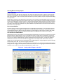
The Usefulness of Marked Data
Suppose that you are trying to capture a signal that appears intermittently, only once every 10 minutes. If you know
generally where the signal appears, you can set an RSA mask trigger to trigger when the amplitude of the signal
breaches a certain threshold. After you stop the capture, you can now see what time the signal appeared. Furthermore, you can choose to download only a portion of the large file to analyze the data – you can even offset the
download to include an amount of time before the trigger was issued. Playback with markers works similarly.
Triggers can also manually be sent through the RSA or other triggering device. If a signal appears as you are watching
the DPX display of the RSA, you can force a trigger at that time.
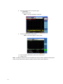
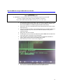
Windowing with markers – marking a signal as it appears and disappears – can be done with the RSA mask trigger by
setting it to issue a trigger when the power threshold is breached, and when the signal goes back below that threshold (False > True > False) – or any similar combination (True > False > True).
Figure 16
Setting a Mask Trigger on the RSA
33
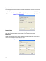
Playback Control
After selecting the file to play back and clicking the Playback button in IQC Control, the Playback Control Panel will
open and display the filename of the selected file.
The original span that was used to record the data will automatically be selected to ensure the proper playback,
though a different span may be selected. Changing the playback span will affect the length of playback: selecting a
larger span will shorten the length of playback, and selecting a smaller span will increase the length of playback.
Figure 17
Playback Control
Repeated Playback
The file may be repeated by selecting the Repeat checkbox and inputting the amount of times to repeat the file. There is
no limit to the amount of times the file may be repeated. The repeat function can be used in conjunction with partial playback to repeat any portion of the file. This allows the flexibility to create a variety of playback scenarios.
Partial Playback
Playing back select portions of a file is possible by selecting the Partial Playback checkbox. This will enable fields to
enter the start and end times in seconds. Playback and capture are handled in blocks of 256 samples, so the time
resolution can be narrowed to the microseconds in most cases.
Figure 18
34
Partial Playback
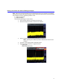
Playback with Markers
Select the Use Markers checkbox to enable the use of capture markers as playback reference. Every capture contains
a beginning and end marker, displayed by default when the Use Markers checkbox is selected; any other markers are
user-implemented during capture. Use the Start Marker and End Marker drop-down lists to select the appropriate
markers to begin and end playback. The Offset text boxes may then be used to add or subtract time from playback
referenced by either the Start or End Marker.
File Download Control
After selecting the file to download and clicking the Download button in IQC Control, the File Download from IQC
Control Panel will open and display the filename of the selected file. This panel functions much like the Playback
control panel. The original span that was used to record the data will automatically be selected to ensure the proper
duration of the file, but the span may be manually changed. This will affect all download operations, so it isn’t
advised to change this setting. Select the Download I File and Download Q File checkboxes to download both the I
and Q portions of the capture. Alternatively, only the I or Q file may be downloaded. The default control PC download location is C:\IQCFiles; this may be changed by accessing Edit > Settings > Directories.
Figure 19
File Download Control
Partial File Transfer
Downloading select portions of a file is possible by selecting the Transfer Partial File checkbox. It is helpful to download only a portion of a very large capture to analyze a specific section of data. Specify the section of the file in seconds to download, or use markers and marker offsets to download select portions. Downloading only select
portions of a file by using markers is an efficient way to skip “wading through” insignificant data. Note that a partial
file download will change the begin and end time of the file in the header.
Figure 20
Partial File Transfer
35
36
Chapter 4
IQC File Format
The IQC file format is an open file format, allowing the user to parse vital statistics located in the header for personal
use.
Naming Convention
The file name is of the following format:
Description_CenterFrequency_CaptureSpan_YYYYMMDD_HHMMSS.xiq
Description -File description entered in capture control
CenterFrequency - Center frequency of capture
CaptureSpan -Bandwidth of capture
YYYYMMDD - Year, Month, Day
HHMMSS - Hours, Minutes, Seconds
Scale Factor
The scale factor is the floating point number that must be multiplied with each I and Q 2 byte signed integer sample
to convert that sample back to the real voltage measured on the signal analyzer. Knowing the actual voltage level of
the signal is critical when making accurate measurements, and when playing back that signal.
In RSA captures, a 32-bit I and Q representation of that floating point number is parsed from the RSA. So for use with
the IQC, the scale factor must be adjusted by 2^16 because the calculation is based on separate I or Q values.
The calculation to recreate an IQC I sample to real voltage is:
Isample • SCF • 65536 = Ivoltage
Where:
Isample = the 16-bit sample value
SCF = the 32-bit scale factor
Ivoltage is the resultant voltage level for that I sample.
Note: The same relative calculation applies for Q values.
37
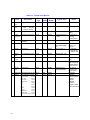
Table 5-4
#
1
2
Field
Header
Size
X-COM
Text
Format of the.XIQ File
Description
Data
Type
Length Beginning
(Bytes)
Offset
Typical Value
Notes
Length of header
Integer
2
0x0000
0x4000 (16384)
0x4000
Static text:
Title
10 bytes
Version 6 bytes
RSA Span
ASCII
16
0x0002
“X-COM IQC v1.2 ”
v1.2
“Span = 110 MHz ”
3
Span
ASCII
16
0x0012
4
32
0x0022
16
0x0042
6
Center
RSA Center Frequency ASCII
Frequenc
y
RBW
RSA Resolution
ASCII
Bandwidth
SCF
Scale Factor
ASCII
32
0x0052
7
Format
File Format
ASCII
16
0x0072
“SCF =
294.5100573488E12 ”
“File Format = 1 ”
8
Marker
Size
Marker
Count
Protect
Size of Markers (bytes) ASCII
18
0x0082
“Marker Size = 26 ”
Number of Markers
ASCII
18
0x0094
Protection Field
ASCII
12
0x00A6
Sample Rate
ASCII
32
0x00B2
2862
13312
0x00D2
0x0C00
“Marker Cnt = 0001 ” Range: 0000 0511
“Protect = 0 ”
0 – Off, 1 – On
IQC Control will
prohibit deletion
of this file if on.
“Sample Rate =
The Sample
6250000.000000 ”
Rate from the
digital source.
Reserved
- Markers - Block Number
– (16kB –
32bytes)
- Sample
Number –
Sample number
within each block
5
9
10
11
Sample
Rate
12
13
Reserved Reserved for future use Binary
Markers Actual Markers: (HEX) Hex
Sample Number
2 bytes
Event Type
2 bytes
Event Count
2 bytes
Block Number
4 bytes
Year
2 bytes
Day
2 bytes
Hour
2 bytes
Minute
2 bytes
Second
2 bytes
Milliseconds
2 bytes
Microseconds
2 bytes
Nanoseconds-unused 2 bytes
* Populated when Device Control is enabled in IQC Control.
38
Discrete RSA
Spans
“Center Frequency = 13 digits of CF
1 GHz ”
including
decimal point*
“RBW = 1 MHz ”
*
See “Scale
Factor ” on
page 37.*
0 – IQC1040
1 – IQC-2110 I
2 – IQC-2110 Q
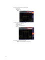
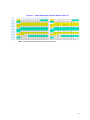
Figure 21
Sample Breakdown of XIQ File Header, fields 1-11
Note: Column between offsets 06 and 07 is simply a visual spacer.
39
40
Chapter 5
Updating the IQC
Updating the IQCServer Software
IQCServer is an application that runs on the I and Q channels of the IQC. Follow these steps to upgrade.
Note: -The ability to upgrade IQCServer is not unlocked during normal use.
1.
2.
3.
4.
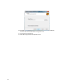
Access the About menu by going to Help About IQC Control.
Enter xcom_server into the text field in the lower-left corner.
Click the button next to it.
Click OK.
Note: This will unlock the menu in the next step.
5.
Access the IQCServer application control menu by going to Edit Manage IQCServer Application.
Note: The current IQCServer for the IQC I and Q channels is shown in the
lower-left corner, followed by the timestamp. The list of archived IQCServers is
shown to the right.
6.
Press Upload New App, browse to new IQCServer and select.
7.
Press Upload New App and browse to the IQCServer.exe file to upload.
41
8.
Right-click on the new file and select Activate This Version of IQCServer.
Note: A message warns that the update will not take effect until the IQC has
been restarted.
9.
Click OK.
Note: The activation will commence and a message will show that the enable
has succeeded.
10.
11.
12.
13.
Click OK.
Access the IQC Settings menu by going to Edit Settings.
Press the Restart the IQC button.
Wait for the IQC to restart.
14. Go back to the IQCServer application control by going to Edit Manage IQCServer
Application.
Note: The current IQCServer for both channels should reflect the upgrade.
Note: The update process also backed up the former version of IQCServer,
according to its timestamp. To revert to a previous version, simply repeat the
process without uploading.
15. Press the Restart the IQC button.
42
Updating the IQC Firmware
The ability to upgrade the IQC Firmware is not unlocked during normal use.
1. Access the About menu by going to Help About IQC Control.
2.
3.
Enter xcom_firmware into the text field in the lower-left corner.
Click the button next to it.
4. Click OK.
Note: This will unlock the menu in the next step.
5.
Browse to and select the .xbin file provided by X-COM.
Note: The firmware upgrade will begin. During this time, a readout of the process will show. After a few minutes, the readout should display that the firmware upgrade was successful, and that a restart of the IQC is required.
6.
Restart the IQC.
Note: Only a reconfiguration between capture and playback modes is
required, but a full power down and back on is recommended.
Note: Notes about IQC firmware upgrade:
•
•
There are 2 types of IQC firmware – capture and playback.
Capture and playback firmware are managed by IQC Control – the user does not
need to select which type of firmware is to be uploaded.
43
44
Chapter 6
Maintenance
Preventive Maintenance
IQC-2110, DP-HD-XXX, and CPG-2110 require do not require preventive maintenance. If any technical or corrective
maintenance needs to be performed, contact Bird Technologies Group customer service.
Replacing Fuse
Note: The fuse is located in the AC module on the back of the blower.
1.
Correct the fuse burnout cause.
Note: Common causes include stuck or blocked fans or a short circuit in the
motor or blower wiring.
2.
3.
Press the locking tab on the fuse drawer and remove the drawer.
Replace the fuse.
4.
Note: See "Specifications" on page 46 for fuse type and current rating.
Press the drawer into the AC module until it locks into place.
Note: If the fans still do not run or if the fuse burns out again, return the unit to
Bird for service.
Troubleshooting
WARNING
To avoid personal injury, disconnect the power cord from the AC line before performing any maintenance,
including fuse replacement or changing the line voltage setting.
Capture
In capture mode, the span is detected as something different than what the RSA is set to (110MHz, 40MHz).
If you are trying to capture:
a) at a 60MHz span and see 110MHz detected
or
b) at any span 20MHz and below and see 40MHz detected,
then the RSA likely has the digital I/Q out count pattern enabled. This is a test feature,
and can be disabled by going to the digital I/Q options screen and changing from count
pattern mode to I/Q output ON mode.
Only one of the drives on the Datapack shows when the IQC starts.
Sometimes the external miniSAS cables may feel like they are all the way in, but are not.
Try shutting down the IQC, taking out and re-inserting the suspect cable at both ends,
and turning on the IQC again.
45
Networking
Using multiple IQCs, and after connecting to one IQC with a computer, another computer cannot be connected.
The Address Resolution Protocol (ARP) table on the workstation has translated the IQC IP
address to the first IQC’s MAC address. The second IQC, if it has the same static IP, will not
have the same MAC address, and connection will be refused. To rectify this, clear your
ARP table by opening an elevated command prompt and executing the command arp -d.
Then, reconnect to the IQC.
Frequently Asked Questions
Q: Why does the IQC capture longer than I specify on a timed capture? (E.g.: I try to capture for 60 s and end up
getting a little more time on playback.)
A: To optimize throughput, due to disk I/O speed limitations, the IQC uses large 512 byte
sectors for disk reads and writes. The IQC always stores an even number of 512 byte sectors
and never stores less than what is requested. On high samples per second captures (40, 60,
and 110MHz) the extra few bytes don't show up because the extra bytes don't add a significant amount of time (< 10 μs) to show up in IQC Control’s playback control. On slower samples per second captures the extra few bytes amount to a greater time factor.
Example - On a 5MHz 45.6 second capture, the IQC stores an extra 384 bytes of I and 384
bytes of Q which amounts to an additional 30 microseconds.
Note: There is no rounding to the 512th byte on playback. The IQC reads
in 512 byte sectors, but can play back the exact amount requested by the
user (resolution is to the sample point – 4 bytes).
Specifications
IQC-2110
Controls
Front Panel
Rear Panel
System ON/OFF, momentary push button
Master Power Toggle Switch
Power
110/230 VAC, 50/60 Hz, 600 W maximum
AC Power Input
115 VAC
230 VAC
110 VAC @ 60 Hz
230 VAC @ 50 Hz
Fuse Rating
115 VAC
230 VAC
IEC 5 x 20 mm Fast acting
10 A
5A
Coling Method
Forced Air
Dimensions
System
Units
IQC 2110
External Memory
Weight
IQC 2110
External Memory
46
19” W x 2” H x 17.25” L
4U
2U
35 lbs
25 lbs
Temperature
Operating
Storage
IQC 2110
External Memory
+5°C to +50°C
-20°C to +70°C
-40°C to +70°C, max gradient 20%/hr
Humidity*
Operating
Non-Operating
5% to 95% non-condensing with a maximum gradient of 20% per hour
5% to 95% non-condensing
Effective Altitude†
Operating
Non-Operating
-200 to +10,000 feet (-60.96 to +3,048 meters)
-200 to +40,000 feet (-60.96 to +12,210 meters)
* Assumes no condensation on the drives.
† Relative to sea level.
CPG-2110
AC Power Input
110 VAC
230 VAC
110 VAC @ 60 Hz
230 VAC @ 50 Hz
Fuse Rating
115 VAC
230 VAC
IEC 5 x 20 mm Fast acting
1A
1A
Coling Method
Radiative
Dimensions
19” W x 3.5” H x 17.25” L
Weight
14 lb
AC Power Input
110 VAC
230 VAC
110 VAC @ 60 Hz
230 VAC @ 50 Hz
Fuse Rating
None
Coling Method
Forced Air
Dimensions
19” W x 3.5” H x 15.75” L
Weight
19 lb
DP-HDD-XXX
47
48
Appendix 1
Capture & Playback Examples
Capture & Playback of FRS 2-Way Radios with the RSA
1.
2.
Connect the CPG to the IQC using the LVDS cables.
Connect the VSG to the CPG using BNC cables.
Note: This example requires a commonly available FRS 2-way radio.
3.
4.
5.
6.
Connect a telescopic antenna to the front RF input.
Change the displays to show the DPX Spectrum and Amplitude vs. Time windows.
Set the center frequency to 480 MHz with a span of 110 MHz.
Power on the 2-way radio and key the microphone.
Note: A strong signal should be displayed on the DPX display window.
7.
Using the Amplitude vs. Time window, set the proper reference level setting.
Note: The signal should approach the reference line but avoid going 6 dB over
due to the overflow that occurs.
8.
9.
Under the Markers tab, click the button Set Peak to locate the marker on the peak of
the signal.
Click on To Center to center the RSA marker.
Note: The RSA markers can be used to quickly center the signal in the display
window.
10. To prepare for capture, set the span to 1 MHz.
Note: The RSA marker will have to be adjusted again.
11. Ensure that the RF Power and Modulation buttons are turned off on the VSG before
capturing data.
12. Open the IQC Control Panel.
13. Click on Capture Data.
14. Ensure the Manual tab is selected.
15. Enter the value of the center frequency and span that corresponds to the settings on
the RSA.
16. Press the Start Capture button to begin.
17. Press the End Capture button to stop the recording.
18. Set the frequency of the VSG to the same center frequency settings recorded on the file.
19. Set the VSG power level to 10 dBm.
20. Ensure the RF power button and Modulation button are set to on.
21. In the IQC Control Panel, select the Playback button.
Note: When transitioning from capture to playback modes, the green LED on
the front of the IQC will flash. When it is solidly lit, the IQC is ready for playback.
22. Ensure to set the span to the same value as recorded.
23. Select Repeat if you wish to continuously loop the playback file.
24. Ensure the 2-way radio is powered on and tuned to the same channel that was
recorded.
25. Press the Start Playback button.
Note: The radio should replay what was previously recorded.
49
Figure 22
File Playback
Capture & Playback of FM Radio with the RSA
1.
2.
3.
4.
5.
Connect the CPG to the IQC using LVDS cables.
Connect the VSG to the CPG using BNC cables.
Connect a telescopic antenna to the front RF input.
Change the displays to show the DPX Spectrum and Amplitude vs. Time windows.
Set the center frequency to an area in the local radio band.
Note: It helps to be familiar with some of the local stations – a center frequency of 97.7 MHz is suitable in the United States) Strong signals should
appear on the DPX display window.
6.
Using the Amplitude vs. Time window, set the proper reference level setting.
Note: The signal should approach the reference line but avoid going 6 dB over
due to the overflow that occurs.
7.
8.
Under the Markers tab, click the button Set Peak to locate the RSA marker on the
peak of one of the signals.
Click To Center to center the marker.
Note: The RSA markers can be used to quickly center the signal in the display
window.
Set the span to 40 MHz to prepare for capture.
Note: The RSA marker will have to be adjusted again.
9.
Verify that the RF Power and Modulation buttons are turned off on the VSG before
capturing data.
10. Open the IQC Control Panel and click Capture Data.
11. Ensure the Manual tab is selected.
50
12. Enter the value of the center frequency and span that corresponds to the settings on
the RSA.
13. Press the Start Capture button to begin.
14. Press the End Capture button to stop recording.
15. Set the frequency of the VSG to the same center frequency settings recorded on the file.
16. Set the VSG power level to 10 dBm.
17. Ensure the RF power button and Modulation button are set to on.
18. In the IQC Control Panel, select the Playback button.
19. Ensure that the span has been set to the same value as the span of the recorded data.
20. Select repeat if you wish to continuously loop the playback file.
21. Press the Start Playback button.
22. On the RSA, navigate to Settings > Audio Demod.
23. Turn the Audio Demod function on.
24. Select either FM or AM, according to the broadcast’s modulation within the capture
that is being listened to.
25. Set the RSA marker to match the frequency of one of the signals.
26. Ensure the volume is turned up both within the Audio Demod module and through
the Windows system volume.
Note: The demodulated radio transmission should be heard. Try centering the
marker on other signals captured.
51
52
Appendix 2
IQC Disk Sanitization
Statement of Compliance
These instructions are only applicable to IQC-2110’s with removable OS drives and are intended to be used with XCOM’s SigAnalyst Workstation (SA-WS).
According to NSA Manual 9-12{1}, Sanitization of Solid State drive can be accomplished by:
“Sanitize EEPROM by overwriting all locations with a known unclassified pattern. Verify
the overwrite procedure by randomly re-reading the overwritten information to confirm
that only the known pattern can be recovered.”
The removable drive carrier in the IQC-2110 uses Intel Solid State Drives (SSD). Intel’s SSD Toolbox software includes
the “secure erase” command that can be issued to the drives from X-COM’s SA-WS.
We have contacted Intel to verify that their secure erase does in fact comply with NSA, DoD and NIST standards.
Below is their response:
“Our SSD drive supports the SATA “Secure Erase” command, which we believe meets all of
these requirements except for AR 380-19. We are making this assumption based upon the
following breakdown of the different specs, and within each looking for the applicable
section governing Flash memory or EEPROMs. If your understanding of the applicable
specifications differs from our view, please let us know which section of each spec applies
most accurately to NAND Solid State Drives and we will re-examine our analysis.
DoD 5220.22-M (also NISPOM)
There were two standards we saw could apply, so both are mentioned here:
http://csrc.nist.gov/publications/nistpubs/800-88/NISTSP800-88_rev1.pdf
Definition: Executing the firmware Secure Erase command (for ATA drives only) and
degaussing are examples of acceptable methods for purging.
Answer: yes, we fully support the Secure Erase command, so we are compliant here
http://it.ouhsc.edu/policies/documents/infosecurity/DoD_5220.pdf
Definition: Nonvolatile RAM (NOVRAM) – Purge: c, g, or m (c.
Overwrite all addressable locations with a single character., g. Remove all power to
include battery power., m. Destroy - Disintegrate, incinerate, pulverize, shred, or melt.)
Answer: yes, our Secure Erase command supports the “c” overwrite with a single character, then “g” and “m” would be done by the operator.
NSA 9-12
http://www.nsa.gov/ia/government/MDG/NSA_CSS_Storage_Device_Declassificatio n_Manual.pdf
Definition: Flash Memory: Sanitize EEPROM by overwriting all locations with a known
unclassified pattern.
Verify the overwrite procedure by randomly rereading the overwritten information to confirm that only the known pattern can be recovered.
Answer: yes, our Secure Erase command will overwrite the drive with a known unclassified pattern (all zeros), and confirmation of that programming is built into the Secure
Erase algorithm. If you want a second confirmation that the drive contains all zeros, the
host system can randomly re-read the drive to verify.
AFSSI5020
http://jya.com/afssi5020.htm#Chapter%205
Definition: 5.1.1. Clearing. Erase EEPROM and EAROM on- or off-circuit. Software that controls
the EEPROM (i.e., PC Card) must not be active (running) during the erasure. Each manufacturer provides mechanisms for writing commands to place these units into Erase, Program,
and Verify modes. In addition, the manufacturer may have its own programming algorithms,
protocols, and erase unit sizes. Use the erase procedures provided by the manufacturer.
53
Normally, this procedure would include pulsing the erase control gate, and verifying the erasure, then, overwriting all bit locations with arbitrary unclassified data.
Answer: yes, our Secure Erase command will run once executed by the host system without
more software interaction, and it pulses the erase control gates to clear all data then verifies
all data has been erased/programmed with known, unclassified data (all zeros).
Navso 5239
http://www.fas.org/irp/doddir/navy/5239_26.htm
Definition: Electrically Erasable PROM (EEPROM) Overwrite all locations with any pattern or
degauss with Type I, II, or other degausser (see 3.4).
Answer: yes, our Secure Erase command will overwrite all locations with a pattern (all zeros).
We have performed verification tests using Intel’s secure erase command with our IQC removable OS drive sled.
After issuing the secure erase command from Intel’s SSD Toolbox we found that all memory addresses were overwritten with zeros.
Sanitization Procedure
Note: These instructions are only applicable to IQC-2110’s with removable OS drives.
Tools needed:
Phillips screwdriver
Software needed:
Intel SSD Toolbox
Hardware needed:
•
•
•
1.
54
X-COM SigAnalyst Workstation (WS) with Windows 7 x64
Removable OS drive sled installed
IQC removable OS drives
Install Removable OS Drive sled in X-COM SigAnalyst Workstation.
1.
a.
Safely shutdown WS and remove from AC power.
b.
The sled is meant to be installed in the either of the bottom two 5.25” drive bays.
c.
Remove both side panels and front panel following the manufacturer’s
instruction manual (see appendix).
d.
Remove bay cover from front panel.
e.
Note: The OS drive slide can be found at the bottom center of the rear panel of
the IQC-2110. If the sled is not found or the unit does not appear to have them
installed (older systems do not have removable drives), contact the X-Com sales
department at 703-390-1087 or [email protected] to obtain a quote for
retrofitting the system.
Slide sled into drive bay and secure using 2 screws on right side of the bay cage.
Screw
Drive Sled
Screw
f.
Connect SATA Cables from sled to WS motherboard
g.
Connect 6 pin molex to WS power supply
h.
Reattach front and both side panels.
i.
Apply AC power to SA-WS power supply.
j.
Turn on SA-WS and boot into Windows7.
k.
If not already installed, install Intel’s SSD Toolbox.
Note: The Intel SSD Toolbox can be downloaded at:
http://downloadcenter.intel.com/Detail_Desc.aspx?agr=Y&DwnldID=18455
l.
Open SSD Toolbox and verify the IQC drives are recognized, Be careful not to
confuse the SA-WS SSDs with the IQC SSDs.
m. Run secure erase command in SSD Toolbox and allow approximately 10 minutes for procedure to complete.
References and standards:
NSA_CSS_Storage_Device_Declassification_Manual.pdf
DSS Clearing and Sanitization matrix.pdf
SP800-88_Aug2006.pdf
Miscellaneous references:
Manual_CM_Storm_Scout.pdf
DP-HD-XXX Disk Purging Procedure
Please refer to the website below for approvals and specs of Jetico’s BC Total Wipe Out.
http://www.idealssi.com/bcwipe-2/
Please read this instruction set in its entirety before proceeding. Contact X-COM with any
questions.
55
Tools Needed
Software
•
Jetico’s BC Wipe Total Wipeout 2.0 software
Hardware
•
•
•
•
•
X-COM SigAnalyst Workstation (SA-WS) with LSI Logic Host Bus Adapter (HBA)
card(s) added to it (See Note Below). Valid model numbers for the HBA include
9201-16e (LSI00276) and 9200-8e (LSI00188)
OR
Laptop with ExpressCard 34/54 slot and Sonnet Tempo SAS ExpressCard 34
X-COM DP-HDD-XXX
2 External Mini-SAS Cables
USB flash drive (2 GB or larger) OR Blank CD
Note: The DP-HDD-XXX is divided into 2 different SAS zones, 1 for IRAID and 1
for QRAID. The LSI HBA is only capable of negotiating with 1 zone at a time. In
order to purge both SAS zones at the same time, the SA-WS will need 2 LSI HBA’s
installed. An HBA is necessary because the Areca RAID cards already installed on
the SA-WS are not capable of relaying the ATA_ERASE command to the RAID.
Create Bootable Wiping Tool
Bootable USB Flash Drive
The following instructions should be used to create a Bootable USB flash drive to run BCWipe:
1. Install BCWipe Total Wipe Out 2.0 in Windows.
2. Open Configuration Wizard from START menu.
3. At Start Options Select “Boot computer and start wiping automatically” and check
“Let me select drives for wiping”.
Note: DO NOT CHECK “Start wiping immediately”.
4.
56
At Log Options Check “Write log file to removable USB or floppy disk”, Click NEXT.
5.
6.
At Wiping scheme, select 7-pass US DoD 5220-22M(ECE) from the drop down menu
and check the Enable Verification Box, Click NEXT.
Check all three boxes:
Reset the Host Protected Area (HPA)
Reset the Device Configuration Overlay (DCO) settings
Replace the last wiping pass by ATA ERASE Command.
•
•
•
7.
8.
Verify your wiping summary is correct and click NEXT.
For Bootable Disk Type, select Bootable USB, and insert USB flash drive (must be 2GB
or larger capacity drive)
9. Highlight USB Flash Drive and click FORMAT and CREATE. When completed click
NEXT.
10. Safely eject and remove your bootable USB drive.
Bootable CD
If a USB thumb drive cannot be used due to security reasons in classified areas, a bootable CD can be made instead
using the following instructions:
57
1.
2.
3.
Install BCWipe Total Out 2.0 in windows.
Open Configuration Wizard from START menu.
At Start Options Select “Boot computer and start wiping automatically” and check
“Let me select drives for wiping”.
Note: DO NOT CHECK “Start wiping immediately”.
4.
5.
At Log Options uncheck “Write log file to removable USB or floppy disk”, Click NEXT.
At Wiping scheme, select 7-pass US DoD 5220-22M(ECE) from the drop down menu
and check the Enable Verification Box, Click NEXT.
6.
Check all three boxes:
• Reset the Host Protected Area (HPA)
•
•
58
Reset the Device Configuration Overlay (DCO) settings
Replace the last wiping pass by ATA ERASE Command.
7.
8.
Verify your wiping summary is correct and click NEXT.
9.
Select the destination and name of the ISO file.
Example - C:\Users\USER\Documents\BCwipe.iso ) and check
Open the destination folder when finished, Click NEXT.
For Bootable Disk Type, select ISO image, and click NEXT.
59
10. The folder with the ISO image should open. Insert blank 700MB CD-R into CD tray
and allow ~30 seconds for Windows to recognize the disc.
11. Find the ISO file and right click.
12. Select Burn Image to Disc from drop down menu.
60
Wipe DP-HDD-XXX using X-COM SA-WS and LSI HBA
CAUTION
BEFORE PROCEEDING:
It is HIGHLY recommended to disconnect the Storage Archive from SA-WS.
If using a Laptop with Sonnet Tempo SAS Host Controller
instead of SA-WS with LSI HBA, the basic process is the same.
1.
With SA-WS completely shut down, connect IRAID on DP-HDD-XXX to LSI HBA
on SA-WS using External Mini-SAS Cable. (If a second HBA is installed in SAWS, connect QRAID to 2nd HBA using External Mini-SAS Cables).
2.
Apply power and turn on DP-HDD-XXX and allow approximately 30 seconds for disk
drives to spin up.
Once spin up time is complete, insert bootable USB drive into available USB port on
SA-WS. (For bootable CD, insert CD into bootable CD-ROM drive after power is
applied to SA-WS).
Apply power and turn on SA-WS.
At BIOS Splash Screen hit F8 to enter Multi-boot option. NOTE: RAID and HBA cards
will initialize before entering the multi-boot display
Select USB device as boot device and press Enter (or CD-ROM for bootable CD
option). Allow 30-60 seconds for BC TotalWipe Out to boot.
Once booted you will see a screen similar to figure 3-1.
3.
4.
5.
6.
7.
8.
You will see 8 (16 if using 2 HBA’s) identical drives for wiping. Highlight each of these
drives and press S. Ensure each drive has the word WIPE next to it.
61
•
The drives in the DP-HDD-XXX are Seagate brand with Model Number structure of:
Figure 23
Brand
Identity
Form
Factor
BC Wipe
Capacity Reserved
ST
9
146
ST = Seagate
3 = 3.5”
in GB
9 = 2.5”
(SAS only)
8
RPM
0
Generation
3
Interface
SS
0 = 10k
FC = Fibre Channel
5 = 15k
LC = 80 Pin (SCA) LVD SCSI
LW= 68 Pin LVD SCSI
NS = Near-Line storage, SATA/SAS
SS = Serial-Attached SCSI
9.
It is possible to accidentally erase the OS drives of the SA-WS.
Note: Double-check that the drives selected are the ones intended for wipe,
BCWipe will permanently delete all the files. Drives with “----“ instead of “WIPE”
will forego the wipe process and data will remain intact. If you have any concerns with which drives should be selected please contact X-COM.
10. Once all desired Drives are selected, press W to start wiping. Wipe time will vary
depending on size of DP-HDD-XXX. For DP-HDD-2TB, wipe time is approximately 20
minutes per pass.
11. If only 1 HBA is installed on the SA-WS or a laptop with the Sonnet Tempo ExpressCard is used, repeat these instructions starting at #1 by connecting the QRAID on DPHDD-XXX (instead of the IRAID) to the LSI HBA on SA-WS using an External Mini-SAS
Cable.
62
Limited Warranty
All products manufactured by Seller are warranted to be free from defects in material and workmanship for a period
of one (1) year, unless otherwise specified, from date of shipment and to conform to applicable specifications, drawings, blueprints and/or samples. Seller’s sole obligation under these warranties shall be to issue credit, repair or
replace any item or part thereof which is proved to be other than as warranted; no allowance shall be made for any
labor charges of Buyer for replacement of parts, adjustment or repairs, or any other work, unless such charges are
authorized in advance by Seller.
If Seller’s products are claimed to be defective in material or workmanship or not to conform to specifications, drawings, blueprints and/or samples, Seller shall, upon prompt notice thereof, either examine the products where they
are located or issue shipping instructions for return to Seller (transportation-charges prepaid by Buyer). In the event
any of our products are proved to be other than as warranted, transportation costs (cheapest way) to and from
Seller’s plant, will be borne by Seller and reimbursement or credit will be made for amounts so expended by Buyer.
Every such claim for breach of these warranties shall be deemed to be waived by Buyer unless made in writing
within ten (10) days from the date of discovery of the defect.
The above warranties shall not extend to any products or parts thereof which have been subjected to any misuse or
neglect, damaged by accident, rendered defective by reason of improper installation or by the performance of
repairs or alterations outside of our plant, and shall not apply to any goods or parts thereof furnished by Buyer or
acquired from others at Buyer’s request and/or to Buyer’s specifications. Routine (regularly required) calibration is
not covered under this limited warranty. In addition, Seller’s warranties do not extend to the failure of tubes, transistors, fuses and batteries, or to other equipment and parts manufactured by others except to the extent of the original manufacturer’s warranty to Seller.
The obligations under the foregoing warranties are limited to the precise terms thereof. These warranties provide
exclusive remedies, expressly in lieu of all other remedies including claims for special or consequential damages.
SELLER NEITHER MAKES NOR ASSUMES ANY OTHER WARRANTY WHATSOEVER, WHETHER EXPRESS, STATUTORY, OR
IMPLIED, INCLUDING WARRANTIES OF MERCHANTABILITY AND FITNESS, AND NO PERSON IS AUTHORIZED TO
ASSUME FOR SELLER ANY OBLIGATION OR LIABILITY NOT STRICTLY IN ACCORDANCE WITH THE FOREGOING.
63
64