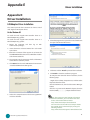
1
Network
Application Platforms
Hardware platforms for next generation networking infrastructure
FW-7541
User's Manual
>>
Publication date:2012-08-01
About
About
Overview
Icon Descriptions
The icons are used in the manual to serve as an indication
of interest topics or important messages. Below is a
description of these icons:
NOTE: This check mark indicates that
there is a note of interest and is something
that you should pay special attention to
while using the product.
WARNING: This exclamation point
indicates that there is a caution or
warning and it is something that could
damage your property or product.
Acknowledgement
Intel, Pentium and Celeron are registered trademarks of
Intel Corp.
Microsoft Windows and MS-DOS are registered trademarks
of Microsoft Corp.
All other product names or trademarks are properties of
their respective owners.
Compliances
CE
This product has passed the CE test for environmental
specifications. Test conditions for passing included the
equipment being operated within an industrial enclosure.
In order to protect the product from being damaged by
ESD (Electrostatic Discharge) and EMI leakage, we strongly
recommend the use of CE-compliant industrial enclosure
products.
FCC Class A
Online Resources
The listed websites are links to the on-line product
information and technical support.
Resource
Website
Lanner
http://www.lannerinc.com
Product
Resources
http://assist.lannerinc.com
RMA
http://eRMA.lannerinc.com
Copyright and Trademarks
This equipment has been tested and found to comply
with the limits for a Class A digital device, pursuant to Part
15 of the FCC Rules. These limits are designed to provide
reasonable protection against harmful interference when
the equipment is operated in a commercial environment.
This equipment generates, uses and can radiate radio
frequency energy and, if not installed and used in
accordance with the instruction manual, may cause
harmful interference to radio communications. Operation
of this equipment in a residential area is likely to cause
harmful interference in which case the user will be required
to correct the interference at his own expense.
Safety Guidelines
Follow these guidelines to ensure general safety:
•
This document is copyrighted © 2102. All rights are
reserved. The original manufacturer reserves the right to
make improvements to the products described in this
manual at any time without notice.
No part of this manual may be reproduced, copied,
translated or transmitted in any form or by any means
without the prior written permission of the original
manufacturer. Information provided in this manual is
intended to be accurate and reliable. However, the original
manufacturer assumes no responsibility for its use, nor for
any infringements upon the rights of third parties that
may result from such use.
Network Application Platforms
•
•
•
•
•
•
Keep the chassis area clear and dust-free during and after
installation.
Do not wear loose clothing or jewelry that could get
caught in the chassis. Fasten your tie or scarf and roll up
your sleeves.
Wear safety glasses if you are working under any
conditions that might be hazardous to your eyes.
Do not perform any action that creates a potential hazard
to people or makes the equipment unsafe.
Disconnect all power by turning off the power and
unplugging the power cord before installing or removing a
chassis or working near power supplies
Do not work alone if potentially hazardous conditions
exist.
Never assume that power is disconnected from a circuit;
always check the circuit.
i
About
About
LITHIUM BATTERY CAUTION:
Risk of Explosion if Battery is replaced by an incorrect type.
Dispose of used batteries according to the instructions
Operating Safety
Electrical equipment generates heat. Ambient air temperature
may not be adequate to cool equipment to acceptable
operating temperatures without adequate circulation. Be sure
that the room in which you choose to operate your system has
adequate air circulation.
Ensure that the chassis cover is secure. The chassis design
allows cooling air to circulate effectively. An open chassis
permits air leaks, which may interrupt and redirect the flow of
cooling air from internal components.
Electrostatic discharge (ESD) can damage equipment and
impair electrical circuitry. ESD damage occurs when electronic
components are improperly handled and can result in complete
or intermittent failures. Be sure to follow ESD-prevention
procedures when removing and replacing components to avoid
these problems.
Wear an ESD-preventive wrist strap, ensuring that it makes
good skin contact. If no wrist strap is available, ground yourself
by touching the metal part of the chassis.
Periodically check the resistance value of the antistatic strap,
which should be between 1 and 10 megohms (Mohms).
EMC Notice
This equipment has been tested and found to comply
with the limits for a Class A digital device, pursuant to Part
15 of the FCC Rules. These limits are designed to provide
reasonable protection against harmful interference when
the equipment is operated in a commercial environment.
This equipment generates, uses, and can radiate radio
frequency energy and, if not installed and used in
accordance with the instruction manual, may cause
harmful interference to radio communications. Operation
of this equipment in a residential area is likely to cause
harmful interference in which case users will be required
to correct the interference at their own expense.
Network Application Platforms
ii
TTaTTable of Contentsbeable of Conten
Chapter 1: Introduction
1
System Specification . . . . . . . . . . . . . . . . . . . . . . . . . . . . . . . . . . . . . . . . . . . . 1
Package Contents . . . . . . . . . . . . . . . . . . . . . . . . . . . . . . . . . . . . . . . . . . . . . . 2
Front Panel Features . . . . . . . . . . . . . . . . . . . . . . . . . . . . . . . . . . . . . . . . . . . . 3
Rear Panel Features . . . . . . . . . . . . . . . . . . . . . . . . . . . . . . . . . . . . . . . . . . . . . 4
Chapter 2: Hardware Setup
5
Preparing the Hardware Installation . . . . . . . . . . . . . . . . . . . . . . . . . . . . . . . . . . 5
Installing the System Memory . . . . . . . . . . . . . . . . . . . . . . . . . . . . . . . . . . . . . . 5
Installing the Hard Disk . . . . . . . . . . . . . . . . . . . . . . . . . . . . . . . . . . . . . . . . . . 6
Installing a CompactFlash Card . . . . . . . . . . . . . . . . . . . . . . . . . . . . . . . . . . . . . 6
Installing 3G SIM Card . . . . . . . . . . . . . . . . . . . . . . . . . . . . . . . . . . . . . . . . . . . 7
Installing Wireless 3G Module . . . . . . . . . . . . . . . . . . . . . . . . . . . . . . . . . . . . . . 7
Mounting . . . . . . . . . . . . . . . . . . . . . . . . . . . . . . . . . . . . . . . . . . . . . . . . . . . 7
Tabletop Mounting . . . . . . . . . . . . . . . . . . . . . . . . . . . . . . . . . . . . . . . . . . 7
Rack Mounting . . . . . . . . . . . . . . . . . . . . . . . . . . . . . . . . . . . . . . . . . . . . . 7
Chapter 3: Motherboard Information
9
Block Diagram . . . . . . . . . . . . . . . . . . . . . . . . . . . . . . . . . . . . . . . . . . . . . . . . 9
Motherboard Layout . . . . . . . . . . . . . . . . . . . . . . . . . . . . . . . . . . . . . . . . . . . 10
Jumper Settings . . . . . . . . . . . . . . . . . . . . . . . . . . . . . . . . . . . . . . . . . . . . . . 11
Chapter 4: BIOS Settings
13
Updating the BIOS . . . . . . . . . . . . . . . . . . . . . . . . . . . . . . . . . . . . . . . . . . . . 13
Accessing the BIOS menu . . . . . . . . . . . . . . . . . . . . . . . . . . . . . . . . . . . . . . . . 14
Navigating the BIOS menu . . . . . . . . . . . . . . . . . . . . . . . . . . . . . . . . . . . . 14
The Main Menu . . . . . . . . . . . . . . . . . . . . . . . . . . . . . . . . . . . . . . . . . . . . 15
Advanced Settings . . . . . . . . . . . . . . . . . . . . . . . . . . . . . . . . . . . . . . . . . 16
Boot Setup . . . . . . . . . . . . . . . . . . . . . . . . . . . . . . . . . . . . . . . . . . . . . . 32
Security Settings . . . . . . . . . . . . . . . . . . . . . . . . . . . . . . . . . . . . . . . . . . . 34
Exit Menu . . . . . . . . . . . . . . . . . . . . . . . . . . . . . . . . . . . . . . . . . . . . . . . 36
Restore on AC Power Loss . . . . . . . . . . . . . . . . . . . . . . . . . . . . . . . . . . . . . 37
Appendix A: Programming Watchdog Timer
38
Appendix B: Setting up Console Redirections
39
iii
TTaTTable of Contentsbeable of Conten
Appendix C: Programming the LCM
40
Appendix D: Programming LAN Bypass
41
Appendix E: Driver Installation
42
LAN Adapters Driver Installation . . . . . . . . . . . . . . . . . . . . . . . . . . . . . . . . . . . 42
On the Windows OS . . . . . . . . . . . . . . . . . . . . . . . . . . . . . . . . . . . . . . . . . 42
On Linux . . . . . . . . . . . . . . . . . . . . . . . . . . . . . . . . . . . . . . . . . . . . . . . . 43
VGA Driver Installation . . . . . . . . . . . . . . . . . . . . . . . . . . . . . . . . . . . . . . . . . . 44
On the Windows OS . . . . . . . . . . . . . . . . . . . . . . . . . . . . . . . . . . . . . . . . . 44
On Linux . . . . . . . . . . . . . . . . . . . . . . . . . . . . . . . . . . . . . . . . . . . . . . . . 44
Appendix F: Terms and Conditions
45
Warranty Policy . . . . . . . . . . . . . . . . . . . . . . . . . . . . . . . . . . . . . . . . . . . 45
RMA Service . . . . . . . . . . . . . . . . . . . . . . . . . . . . . . . . . . . . . . . . . . . . . 45
iv
Chapter 1
Introduction
Chapter 1:
Introduction
System Specification
Thank you for choosing the FW-7541. The FW-7541 is
a desktop network communication appliance which is
built on Intel® Pineview™ embedded processor, the nextgeneration in the Intel ® Atom™ family.
FEATURE
The FW-7541 is an ideal network system platform. All
electronics are protected in a compact sealed rugged case
for easy installation in customers’ computer facilities, or it
can be used as a stand-alone application situated in your
lab or offices where space is limited and the environment
is harsh.
The FW-7541 can be used as a standalone system, rack
mounted or desktop mounted. The system comes in a
footprint of only 174mmx140mm (6.85” x 5.51”).
The rugged aluminum case not only provides great
protection from EMI, EDS, shock/vibration, cold and heat,
but also passive cooling for quiet fanless operation (Models
C and D are fanless; models A and B are with fans)
The six Gigabit LAN ports with hardware bypass (1 pair)
capability and Mini-PCIe slot coupled with SIM card
connector answer the demand for versatility in networking
applications. It also supports a 2.5” SATA HDD and
CompactFlash for storage. All of the above mentioned are
packed into a small rugged unit (268mmx40mmx145mm)
(10.55”x1.57”x5.71”).
Please refer to the chart below for a summary of the
system’s specifications.
Form Factor
Desktop
Processor
Onboard Dual-Core Intel®
ATOM D525
1.8 GHz
Chipset
Intel ICH8M
Technology
DDR3 667/800 MHz, non-ECC
Max Capacity
4GB
Socket
1x204P SO-DIMM
Platform
System Memory
Windows (2000, 2003, XP)
Linux Kernel 2.4 and up
OS Support
Storage
Networking
I/O Interface
Expansion
Cooling
Environmental
Parameters
Miscellaneous
Physical
Dimensions
Power
Approvals &
Compliance
Ordering Info
Network Application Platforms
DESCRIPTION
HDD Bay(s)
1 x 2.5”
Storage Interface
1 x Serial ATA, 1 x CompactFlash
Ethernet Ports
6 x GbE ports
Controller
1 x Intel 82574L LAN Chip
5 x Intel 82583V LAN Chip
By-Pass
1 pair optional
Console
1 x RJ45
USB 2.0
2 x USB 2.0
Mini-PCIe
1
Processor
Passive Heatsink
System
Passive Heatsink
Temperature, ambient
operating / storage
0ºC ~40ºC / -20ºC~70ºC
Humidity (RH), ambient operating and non-operating
5 ~ 95%, non condensing
Watchdog
Yes
Internal RTC with Li Battery
Yes
Dimensions (WxHxD)
268x 40 x 145mm
Weight
1.2KG
Type / Watts
60W Adapter
System Input
12V DC
CE Emission, FCC Class A, RoHS
Please note that Fanless models (models C/D) only support
industrial HDD
1
Chapter 1
Introduction
Package Contents
Your package contains the following items:
•
FW-7541 Network Security Platform
•
Power cable
•
1 crossover Ethernet cable (1.8 meters)
•
1 straight-through Ethernet cable (1.8 meters)
•
1 RJ-45 to DB-9 female console cable
•
Serial-ATA hard drive cable
•
1 tabletop mounting screw pack
•
1 hard disk installation screw pack (only supplied with
systems shipped without pre-installed hard disks)
including the following items:
•
ESD protection pad to cover the exposed screws
from hard disk installation
•
Hard disk mounting screws
•
Hard disk anti-vibration rubber (blue)
For instructions on hard disk installation, refer to Installing
the Hard Disk on Chapter 2 Hardware Setup.
•
•
(Optional accessory) Rack mounting kit which
contains the following items:
•
Rack mounting bracket
•
Rack mounting screw pack including cable holder
and screws for rack mounting (flat head screws)
and cable holder (threaded oval head screws)
Drivers and user’s manual CD.
Network Application Platforms
2
Chapter 1
Introduction
Front Panel Features
F4
F1
F2
F3
LAN1 LAN2 LAN3 LAN4 LAN5 LAN6
F1 Console Port
By using suitable rollover cable (Cisco console cable), you can connect to a computer terminal
for diagnostic or configuration purpose. Terminal Configuration Parameters: 115200 baud, 8 data
bits, no parity, 1stop bit, and no flow control.
F2 HDD/Status/Power LED
HDD: If the LED blinks, it indicates data access activities; otherwise, it remains off.
Status: This LED is programmable. You could program it to display the operating status with the
behavior like:
If the LED is green, it indicates that the system’s operational state is normal. If it is amber, it
indicates that the system is malfunctioning.
Power: If the LED is on it indicates that the system is powered on. If it is off, it indicates that the
system is powered off.
F3 Two USB 2.0 Ports
It connects to any USB devices, for example, a flash drive.
F4 6 Gigabit LAN ports
Left LED:If the LED is green, it indicates that the connection speed is 100Mbps.
If the LED is orange, it indicates that the connection speed is 1000Mbps.
Right LED: If the LED is on, it indicates that the port is active. If it blinks, it indicates there is
traffic.
Using suitable RJ-45 cable, you can connect FW-7541 System to a computer, or to any other piece
of equipment that has an Ethernet connection; for example, a hub or a switch. Moreover,1 pair
(LAN1-LAN2) can be configured as LAN Bypass when failure events occur. LAN 1 is also capable of
the Preboot Execution Environment (PXE) function. The LAN Bypass feature can be implemented
with watch dog timer functionality. Look for the Driver and User’s Manual CD for sample codes
on this function. (Read Appendix C for more information).
Note:
111 The availability of LAN Bypass varies depending on the model as listed below:
Model
Bypass or not
MB-7541A/C
Yes
MB-7541B/D
No
222 Both PXE and Lan Bypass functionalities can be enabled or disabled in the BIOS.
Network Application Platforms
3
Chapter 1
Introduction
Rear Panel Features
R1
R1
R2
R3
R2
R3
R4
R1 Reset Switch
Use a pointed object to press the reset button for about 3 seconds to reboot the system without
turning off the power.
R2 Power-on Switch
It is a switch to turn on or off the power.
R3 AC Power-in socket
The system requires a 60W/12V switching power supply with lock.
R4 System fan (only on models A and B)
Note: Models C and D are fanless; models A and B are with fans.
Network Application Platforms
4
Chapter 2
Hardware Setup
Chapter 2:
Hardware Setup
Preparing the Hardware Installation
To access some components and perform certain service
procedures, you must perform the following procedures
first.
WARNING: To reduce the risk of personal injury,
electric shock, or damage to the equipment,
remove the power cord to remove power from the
device. The Power On/Standby button on the back
panel does not completely shut off system power.
Portions of the power supply and some internal
circuitry remain active until AC power is removed.
Notch
Cutout
Note:
1. SO-DIMM
installed must meet the following
speed requirement: DDR3 667/800 MHz. Do not
install DIMMs with different speeds.
2. The motherboard equips with one SO-DIMM
socket — all models can support up to 4GB
capacity in maximum .
1. Unscrew the 6 screws from the top cover of the FW7541 System.
2. Open the cover.
Installing the System Memory
The motherboard supports DDR3 memory that features
data transfer rates of 667/800MHz to meet the higher
bandwidth requirements of the latest operating system
and Internet applications. It comes with one Double Data
Rate Type Three (DDR3) Small Outline Dual Inline Memory
Module (SO-DIMM) socket.
1. Align the memory module’s cutout with the the SODIMM’s slot notch.
2. Install the SO-DIMM.
Network Application Platforms
5
Chapter 2
Installing the Hard Disk
Hardware Setup
4
The system can accommodate one Serial-ATA disk (2.5”).
Follow these steps to install a hard disk into the FW-7541:
1. Take off the black cap covering the hard disk mounting
holes and insert the anti-vibration rubber to the
mounting holes. Make sure that the rubber goes
through the holes when inserting it.
2. Place hard disk inside the cover and align the corners of
the hard disk with the mounting holes on the cover.
3. Secure the hard disk with 4 mounting screws from the
outside of the cover.
4. Use the ESD protection pad in the hard disk installation
screw pack to cover the exposed screws for ESD
protection
Note:
1. To Secure a 2.5” hard disk to the tray, use the
mounting holes and fasten it with the screws
from the outside of the chassis cover as
illustrated in step 3 . Make sure that you use
the ESD protection pad to cover the exposed
screws for ESD protection .
2. Fanless models (models C/D) only support
industrial hard disk.
5. Connect the Serial-ATA cables to the HDD.
6. Plug the Serial-ATA drive and power cables to the
Serial-ATA drive and the 4-Pin Serial-ATA Power
connectors on the main board respectively.
1
Installing a CompactFlash Card
FW-7541 provides one CompactFlash slot. Follow the
procedures bellow to install a CompactFlash card.
1. Align CompactFlash card and the card slot with the
arrow pointing toward the connector.
2
2. Push the card to insert into the connector.
1
2
3
Network Application Platforms
6
Chapter 2
Hardware Setup
Installing 3G SIM Card
Mounting
1. Unlock the SIM card tray.
2. Align the SIM card and the tray with the cut-off
angle.
3. Insert the SIM card into the tray.
4. Close the tray and lock it on the board.
Tabletop Mounting
To mount the FW-7541 on the table, use the screws and
rubber feet in the tabletop mounting screw pack. Follow
the following procedures as a guideline:
1. Place the rubber feet on the mounting hole at the
bottom of the FW-7541 and fix it firmly by using the
screws provided.
3
2. Place the FW-7541 on the table with the rubber feet
standing on top of the table.
4
Note: To remove the SIM card, unlock the tray first
by sliding it outward.
Rack Mounting
Installation environment precaution:
Installing Wireless 3G Module
1.
1. Align the wireless module’s cutout with the Mini-PCIe
slot notch.
2. Insert the wireless module into the connector
diagnoally.
3. Push the other end of the wireless module to be
tightened with the latch.
2.
2
3.
3
4.
1. Note:
To remove the module from the system,
release the latch first by slightly bending it inward.
Network Application Platforms
Elevated Operating Ambient - If installed in a
closed or multi-unit rack assembly, the operating
ambient temperature of the rack environment
may be greater than room ambient. Therefore,
consideration should be given to installing
the equipment in an environment compatible
with the maximum ambient temperature (Tma)
specified by the manufacturer.
Reduced Air Flow - Installation of the equipment
in a rack should be such that the amount of air
flow required for safe operation of the equipment
is not compromised. Mechanical Loading Mounting of the equipment in the rack should
be such that a hazardous condition is not created
due to uneven mechanical loading.
Mechanical Loading - Mounting of the equipment
in the rack should be such that a hazardous
condition is not achieved due to uneven
mechanical loading.
Circuit Overloading - Consideration should be
given to the connection of the equipment to the
supply circuit and the effect that overloading
of the circuits might have on over-current
protection and supply wiring. Appropriate
7
Chapter 2
5.
consideration of equipment nameplate ratings
should be used when addressing this concern.
Reliable Earthing - Reliable earthing of rackmounted equipment should be maintained.
Particular attention should be given to supply
connections other than direct connections to the
branch circuit (e.g. use of power strips).”
CAUTION : Rail/rack mounted equipment is not
to be used as a shelf or a work space.
To mount the FW-7541 onto the rack, use the mounting
kit with the screw pack. Follow the following procedures
as a guideline:
1. Place the FW-7541 on the rack mounting bracket and
fix it to the bracket by using the flat head screws in the
screw pack.
Hardware Setup
Connecting Powers
Follow theses procedures to power up the FW-7541:
1. Connect one end of the power adapter to the DC jack
of the FW-7541 first.
2. Connect the other end of the power cord to the DC
power adapter.
3. Lastly, connect the power cord to an electrical outlet.
CAUTION: Leave space around your power
adapter. Do not use this device in a location where
airflow around the power adapter or computer
is not sufficient. Always disconnect the power
adapter before opening the computer to perform
procedures such as installing memory or removing
the hard disk.
2. Place the power adaptor in the adaptor slot and attach
the cable holder (with threaded oval-head screws)
provided to the rack mounting bracket. Make sure
that the power adaptor socket is not blocked by the
aligning holder in the front.
3. You could use the cable holder to hold your cable
to prevent it from tangling as shown in the picture
below.
Note: Bracket mounting screws for mounting the
bracket onto the rack equipment are not included.
The original screw pack is for fixing system on the
bracket.
Network Application Platforms
8
Chapter 3
Motherboard Information
Chapter 3:
Motherboard Information
Block Diagram
The block diagram depicts the relationships among the
interfaces or modules on the motherboard. Please refer
to the following figure for your motherboard’s layout
design.
Up to 4GB
MAX
1x DDR3
667/800Mhz SO-DIMM
2 x 6 Pin Header
VGA
D525 Processor
X4 DMI
2x USB 2.0
2x USB 2.0
Pin Header
USB 2.0
CFII socket
Mini PCI-E socket
2 x SATA II
RJ45 Console
Port
Console Pin
header
Winbond
W83627DHG-P
LPC
6x PCI-E
x1
KB/Mouse
Intel
82574L
1 x 2.5" HDD
Bay supported
on the system
Intel
82583V
Intel
82583V
Intel
82583V
Intel
82583V
Intel
82583V
1 pair bypass on models A/C
Network Application Platforms
9
Chapter 3
Motherboard Information
Motherboard Layout
The motherboard layout shows the connectors and
jumpers on the board. Refer to the following picture
as a reference of the pin assignments and the internal
connectors.
VGA Interface
Clear CMOS
Hardware and
Software Reset
jumper
ATX Power
Button
SO-DIMM
Socket
Compact Flash
Connector
SPI ROM Update
Connector
Fan
Connector
LPC I/O bus
(Port 80)
SATA 1/2 Connectors
140mm
Keyboard and
Mouse Connectors
SATA Power
Connector
Mini PCI-E
Connector
SIM Card
Serial Port
Connector
Socket
Console Port
Ethernet Ports
USB2.0 Ports
USB 2 and 3
Connectors
174mm
Network Application Platforms
10
Chapter 3
Motherboard Information
Jumper Settings
SO-DIMM Socket (CN1): The single memory slot (204 pin)
is for connecting the DDR3 SO-DIMM (Small Outline
Dual In-line Memory Module) 667/800 memory. The
system can suport up to 4 GB in maximum.
FAN Connector (FAN1): The 3-pin connector is for
connecting the system fan.The BIOS will list the CPU
and system fans’ monitored temperature and speed
under the menu of Hardware Health Configuration.
You could also configure the target temperature to
adjust the fan speed automatically.
1
2
3
Function
PIN NO.
Ground
1
+12V Fan Status
2
3
ATX Power Button (CN2): The power button has a 2-pin
connector; the pin definition is as the following:
V-SYNC H-SYNC Blue Green Red
9
7
5
3
1
Pin name
PANSW
GND
VGA Interface (J1): It is for connecting the VGA interface
cable.
CompactFlash Connector (CN4): It is for connecting a
Compact Flash card to be served as your system's
storage. The socket is CF type II and can fit into both
bype I and type II cards.
Serial-ATA Power Connector (J8): It is used for connectig
the SATA power cord.
PIN NO.
Function
1
VCC(12V)
VGA Interface Connector (J1): VGA Interface (J1): It is for
connecting the VGA interface cable (2x6 to female
DB15).
F u n c - DD_
tion DATA
PIN NO.
11
Pin No.
1
2
1
2
2
GND
3
GND
4
VCC(5V)
4
3
2
1
Keyboard and Mouse Connector (J7): It is for connectig
the PS/2 keyboard and mouse interface cable.
11 9 7 5 3 1
12 10 8 6 4 2
PIN NO.
12
10
8
6
4
2
F u n c - DD_CLK GND GND GND GND C R T
tion
ON
Hardware or Software Reset Jumper(JP2): The jumper
can be adjusted to be in either hardware or software
reset mode when the reset switch is pressed. The
1
hardware reset
will reboot the system without turning
off the power.
2 The software reset can be programmed
to reset a software
to its default setting.
3
1
2
3
Pin No.
1-2
2-3
Function
Software Reset
Hardware Reset
Clear CMOS jumper (JP1): It is for clearing the CMOS
memory 1and system setup parameters by erasing
the data 2stored in the CMOS RAM such as the system
passwords.
3
1
2
3
P i n Function
No.
1
VCC
3
MSDATA
5
KBDATA
7
GND
1
3
5
7
2
4
6
8
Pin No. Function
2
MSCLK
4
KEY
6
KEY
8
KBCLK
SATA 1 and 2 Connectors(J5, J6): It is for connecting
a 2.5’’ SATA harddisk to be served as your system’s
storage. The ICH8 chipset supports the Serial ATA
Specification Revision 2.5. with data transfer rates up
to 3.0 Gb/s(300 MB/s). Note that models E/F/G/H only
support industrial Hard disk.
1
2
3
4
5
6
7
Pin No.
1
2
3
4
5
6
7
Function
Ground
Ground
TX+
TXGround
RXRX+
Pin No.
Function
1-2 (Default)
Normal
2-3
Clear CMOS
Network Application Platforms
11
Chapter 3
Motherboard Information
The controller contains two modes of operation—a
legacy mode using I/O space, and an AHCI mode
using memory space. Software that uses legacy
mode will not have AHCI capabilities.
SPI-ROM Update Connector (J3): Using the appropriate
cable to connect this 10-pin ISP pin header connector,
the user can update the SPI Flash soldered on board.
The AHCI ( Advanced Host Controller Interface) is a
programming interface which defines transactions
between the SATA controller and software and
enables advanced performance and usability with
SATA. Platforms supporting AHCI may take advantage
of performance features such as no master/slave
designation for SATA devices—each device is treated
as a master—and hardware assisted native command
queuing. AHCI also provides usability enhancements
such as Hot-Plug. Here is the list of the AHCI capabilities
which exist in the system:
Function
Pin No.
NC
SPI_CS0
SPI_ICH_MISO
KEY
GND
1
3
5
7
9
1. Hardware assisted native command queuing
2. Aggressive power management
3. LED indicator support
Note: To configure your hard disk as AHCI
compatible, use the BIOS menu. Refer to IDE
Configuration Settings on Chapter 4 BIOS Settings.
Also, Intel(R) Matrix Storage Manager (for use on
systems using Intel(R) 82801HBM I/O Controller
Hub (ICH8M)- AHCI only) has to be installed, for
more information, visit http://downloadcenter.
intel.com/Detail_Desc.aspx?lang=eng&chan
geLang=true&DwnldId=19607
Serial Interface Connectors(J9): It is for connecting the
RS-232 serial port module cable. This is COM2 where
as the external console port (RJ45) is COM1.
Function
Pin No.
Data Carrier
1
Detected
Received Data
3
Transmitted
5
Data
Data Terminal
7
Ready
Signal Ground
9
1
3
5
7
9
Function
2 Pin No.
2
Data
Set Ready
4
4
Request
to
6
Send
8
6
Clear to Send
10
8
Ring Indicator
10 Signal Ground
Network Application Platforms
1
3
5
7
9
2
4
6
8
10
Pin No. Function
2
NC
4
V_3P3_SPI
6
8
10
SPI_HOLD0_L
SPI_ICH_CLK
SPI_ICH_
MOSI
LPC I/O bus (Port 80 output for Debug Card) (J4):
It is Intel proprietary connector for connecting a
checkpoint device to output checkpoints throughout
bootblock and Power-On Self Test (POST) to indicate
the task the system is currently running.
Pin No.
10
8
6
4
2
Function
10
GND
8
GND
6
+3.3V
LPC_LAD0 4
LPC_LAD1 2
9
7
5
3
1
Pin No.
Function
9
7
5
3
1
LPC_AD2
LPC_AD3
LPC_FRAME_N
RST_80DGPT_N
CLK_33M_P80
SIM Card Tray (CN5): It is for connecting SIM card for
mobile Internet connection.
Mini-PCIe Socket(CN6): It is for connecting WiFi module
to serve Wireless LAN connections or connecting
Wireless 3G module for mobile Internet connections.
The socket is provided through the Universal Serial
Bus (USB) 2.0 host interface.
USB Connector(USB 2 and 3, J11) : It is for connecting
the USB module cable. It complies with USB2.0 and
is capable of low-speed, full-speed, and high-speed
which can support up to 480 Mbps connection
speed.
Function
Pin No.
USB_VCC
Key
USBD0USBD0+
Ground
1
3
5
7
9
1
3
5
7
9
2
4
6
8
10
Pin No.
Function
2
Ground
4
USBD1+
6
USBD18
Key
10 USB_VCC
12
Chapter 4
Bios Settings
Chapter 4:
BIOS Settings
Updating the BIOS
The Basic Input/Output System (BIOS) can be updated
using the designated Flash Utility. To obtain the utility,
please contact us either through the sales rep or technical
support.
Note:
For the update version of the BIOS image, please
visit Lanner’s support page at
http://assist.lannerinc.com. Then select support
center from the Main Menu and look under the
folder for the desired product category. The
resources for each product including the BIOS
image will be contained within a folder named by
the product model.
Network Application Platforms
13
Chapter 4
Bios Settings
Accessing the BIOS menu
You will need to enter the BIOS Setup program to configure
the system when you are installing a motherboard or
when the system prompts “Run Setup” during start-up.
This section explains how to configure your system using
this program.
Even if you have never enter the BIOS Setup program
when you are installing a motherboard, you can change
the configuration of your computer in the future with
the BIOS Setup program. For example, you may want to
enable the security password feature or change the power
management settings. This requires you to configure
your system using the BIOS Setup program so that the
computer can recognize these changes and record them
in the CMOS RAM .
The Setup program is designed to make it as easy to use as
possible. Being a menu-driven program, it lets you scroll
through the various sub-menus and make your selections
from the available options using the navigation keys.
Note: This manual describes the standard look of
the setup screen. There may be some instances in which
the motherboard features can vary from one to another
due to customization. This means that some of the options
described in this manual mays not match that of your
motherboard’s AMIBIOS.
Navigating the BIOS menu
The BIOS setup utility uses a key-based navigation system
called hot keys. Most of the BIOS setup utility hot keys can
be used at any time during the setup navigation process.
Keys
-><- Left/Right
->
>-
When you start up the computer, the system provides you
with the opportunity to run this program. Press <Delete>
during the Power-On-Self-Test (POST) to enter the Setup
utility (There are a few cases that other keys are used, such
as <F1>, <F2>, and so forth.); otherwise, POST continues
with its test routines.
Up/Down
+- Plus/Minuss
Tab
Description
The Left and Right <Arrow> keys
allow you to select an setup screen.
For example: Main screen, Advanced
screen, Boot screen, and so on.
The Up and Down <Arrow> keys
allow you to select an setup item or
sub-screen.
The Plus and Minus <Arrow> keys
allow you to change the field value
of a particular setup item. For
example: Date and Time.
The <Tab> key allows you to select
setup fields.
Note: The <F8> key on your keyboard is the FailSafe key. It is not displayed on the key legend by default.
To set the Fail-Safe settings of the BIOS, press the <F8>
key on your keyboard. It is located on the upper row of
a standard 101 keyboard. The Fail-Safe settings allow
the motherboard to boot up with the least amount of
options set. This can lessen the probability of conflicting
settings.
These keys include <F1>, <F10>, <Enter>, <ESC>, <Arrow>
keys, and so on.
Network Application Platforms
14
Chapter 4
Bios Settings
The Main Menu
The main BIOS setup menu is the first screen that you can
navigate. Each main BIOS setup menu option is described
in this chapter.
The Main BIOS setup menu screen has two main frames. The
left frame displays all the options that can be configured.
“Grayed-out” options are configured parameters and
cannot be modified. On the other hand, Options in blue
can be modified.
The right frame displays the key legend. Above the key
legend is an area reserved for a text message. When an
option is selected in the left frame, it is highlighted in
white. Often a text message will accompany it.
System Time/System Date
Use this option to change the system time and date.
Highlight System Time or System Date using the <Arrow>
keys. Enter new values through the keyboard. Press the
<Tab> key or the <Arrow> keys to move between fields.
The date must be entered in MM/DD/YY format. The time
is entered in HH:MM:SS format.
Network Application Platforms
15
Chapter 4
Bios Settings
Advanced Settings
Select the Advanced tab from the setup screen to enter
the Advanced BIOS Setup screen. You can select any of
the items in the left frame of the screen, such as SuperIO
Configuration, to go to the sub menu for that item. You
can display an Advanced BIOS
Setup option by highlighting it using the <Arrow> keys.
All Advanced BIOS Setup options are described in this
section. The Advanced BIOS Setup screen is shown at
the right. The sub menus are described on the following
pages.
CPU Configuration
This setting allows the users to view and configurae the
settings of the CPU installed on the system.
Option
Manufacturer
CPU Frequency/
FSB Speed
Cache L1, Cache
L2
Ratio Actual
Value
MAX CPUID
Value Limit
Description
This shows the CPU brand name.
This shows the CPU frequency and Front Side
Bus frequency in Megahertz.
This specifies the size of the Level 1 and Level
2 caches in Kilobytes.
This shows the actual CPU ratio.
The CPUID tells the OS/BIOS what the
maximum capabilities are for the processor.
When enabled, the processor will limit the
maximum CPUID input value to 03h when
it is queried by the operating system, even if
the processor supports a higher CPUID input
value.
When disabled, the processor will return the
actual maximum CPUID input value of the
processor when it is queried by the operating
system. It is recommended that you leave it
at the default setting of Disabled. You should
only enable it if you intend to use the Intel
Pentium 4 processor with Hyper-Threading
Technology with an operating system that
does not support it.
Execute-Disable Execute Disable Bit is an Intel hardware-based
Bit Capability
security feature that can reduce exposure to
viruses and malicious-code attacks. To use
Execute Disable Bit, you must also install a
supporting operating system.
Network Application Platforms
16
Chapter 4
Bios Settings
Option
Description
Hyper Threading This option allows the user to enable or
Technology
disable the HyperThreading™ support of
the Intel® HT capable processors. By default
this setting is enabled. This setting should
be disabled in Microsoft™ Windows 2000 or
older systems.
IDE Configuration Settings
You can use this screen to select options for the IDE
Configuration Settings. Use the up and down <Arrow>
keys to select an item. Use the <Plus> and <Minus> keys to
change the value of the selected option. A description of
the selected item appears on the right side of the screen.
The settings are described on the following pages. An
example of the IDE Configuration screen is at the right.
Primary IDE Master, Primary IDE Slave, Secondary IDE Master,
Secondary IDE Slave:
Select one of the hard disk drives to configure it. Press
<Enter> to access its the sub menu. The options on the
sub menu are described as in the following..
Network Application Platforms
17
Chapter 4
Bios Settings
Primary /Secondary IDE Master and Slave Sub Menu
From the IDE Configuration screen, press <Enter> to
access the sub menu for the primary/secondary IDE
master and slave drives. Use this screen to select options
for the Primary and Secondary IDE drives. Use the up and
down <Arrow> keys to select an item. Use the <Plus> and
<Minus> keys to change the value of the selected option.
The settings are described on the following pages. The
screen for the Primary IDE Master is shown at the right.
Type
This option sets the type of device that the AMIBIOS
attempts to boot from after the Power-On-Self-Test (POST)
has completed.
Option
Description
Not Installed Set this value to prevent the BIOS from
searching for an IDE disk drive on the specified
channel.
Auto
Set this value to allow the BIOS to automatically
detect the IDE disk drive type attached to the
specified channel. This setting should be used
if an IDE hard disk drive is attached to the
specified channel. This is the default setting.
CDROM
This option specifies that an IDE CD-ROM drive
is attached to the specified IDE channel. The
BIOS will not attempt to search for other types
of IDE disk drives on the specified channe.
ARMD
This option specifies an ATAPI Removable
Media Device.
This includes, but is not limited to:
• ZIP
• LS-120
LBA/Large Mode
LBA (Logical Block Addressing) is a method of addressing
data on a disk drive.
Option
Disabled
Auto
Description
Set this value to prevent the BIOS from using
Large Block Addressing mode control on the
specified channel.
Set this value to allow the BIOS to automatically
detect the Large Block Addressing mode control
on the specified channel. This is the default
setting.
Block (Multi-Sector Transfer)
This option sets the block mode multi sector transfers
option.
Network Application Platforms
18
Chapter 4
Option
Disabled
Auto
Bios Settings
Description
Set this value to prevent the BIOS from using
Multi-Sector Transfer on the specified channel.
The data to and from the device will occur one
sector at a time.
Set this value to allow the BIOS to automatically
detect device support for Multi-Sector Transfers
on the specified channel. If supported, Set this
value to allow the BIOS to automatically detect
the number of sectors per block for transfer
from the hard disk drive to the memory. The
data transfer to and from the device will occur
multiple sectors at a time. This is the default
setting.
PIO Mode
IDE PIO (Programmable I/O) mode programs timing
cycles between the IDE drive and the programmable
IDE controller. As the PIO mode increases, the cycle time
decreases.
Option
Auto
0
1
2
3
4
Description
Set this value to allow the BIOS to auto detect
the PIO mode. Use this value if the IDE disk
drive support cannot be determined. This is the
default setting.
Set this value to allow the BIOS to use PIO mode
0. It has a data transfer rate of 3.3 MBs.
Set this value to allow the BIOS to use PIO mode
0. It has a data transfer rate of 5.2 MBs.
Set this value to allow the BIOS to use PIO mode
0. It has a data transfer rate of 8.3 MBs.
Set this value to allow the BIOS to use PIO mode
0. It has a data transfer rate of 11.1MBs.
Set this value to allow the BIOS to use PIO
mode 4. It has a data transfer rate of 16.6 MBs.
This setting generally works with all hard disk
drives manufactured after 1999. For other disk
drive, such as IDE CD-ROM drives, check the
specifications of the drive.
DMA Mode
This setting allows you to adjust the DMA (Direct memory
access) mode options.
Option
Auto
SWDMA0
Description
Set this value to allow the BIOS to automatically
detect the DMA mode. Use this value if the IDE
disk drive support cannot be determined. This is
the default setting.
Set this value to allow the BIOS to use Single
Word DMA mode 0. It has a data transfer rate of
2.1 MBs.
Network Application Platforms
19
Chapter 4
Option
SWDMA1
SWDMA2
MWDMA0
MWDMA1
MWDMA2
UDMA0
UDMA1
UDMA2
UDMA3
UDMA4
UDMA5
UDMA6
Bios Settings
Description
Set this value to allow the BIOS to use Single
Word DMA mode 1. It has a data transfer rate of
4.2 MBs.
Set this value to allow the BIOS to use Single
Word DMA mode 2. It has a data transfer rate of
8.3 MBs.
Set this value to allow the BIOS to use Multi Word
DMA mode 0. It has a data transfer rate of 4.2
MBs.
Set this value to allow the BIOS to use Multi Word
DMA mode 1. It has a data transfer rate of 13.3
MBs.
Set this value to allow the BIOS to use Multi Word
DMA mode 2. It has a data transfer rate of 16.6
MBs.
Set this value to allow the BIOS to use Ultra DMA
mode 0. It has a data transfer rate of 16.6 MBs.
It has the same transfer rate as PIO mode 4 and
Multi Word DMA mode 2.
Set this value to allow the BIOS to use Ultra DMA
mode 1. It has a data transfer rate of 25 MBs.
Set this value to allow the BIOS to use Ultra DMA
mode 2. It has a data transfer rate of 33.3 MBs.
Set this value to allow the BIOS to use Ultra DMA
mode 3. It has a data transfer rate of 44.4 MBs. To
use this mode, it is required that an 80-conductor
ATA cable is used.
Set this value to allow the BIOS to use Ultra DMA
mode 4. It has a data transfer rate of 66.6 MBs. To
use this mode, it is required that an 80-conductor
ATA cable is used.
Set this value to allow the BIOS to use Ultra DMA
mode 5. It has a data transfer rate of 99.9 To use
this mode, it is required that an 80-conductor
ATA cable is used.
Set this value to allow the BIOS to use Ultra DMA
mode 6. It has a data transfer rate of 133.2 MBs. To
use this mode, it is required that an 80-conductor
ATA cable is used.
S.M.A.R.T. for Hard disk drives
Self-Monitoring Analysis and Reporting Technology
(SMART) feature can help predict impending drive
failures.
Option
Auto
Disabled
Enabled
Description
Set this value to allow the BIOS to automatically
detect hard disk drive support. Use this setting if
the IDE disk drive support cannot be determined.
This is the default setting.
Set this value to prevent the BIOS from using the
SMART feature.
Set this value to allow the BIOS to use the SMART
feature on support hard disk drives.
Network Application Platforms
20
Chapter 4
Bios Settings
32Bit Data Transfer
This option sets the 32-bit data transfer option.
Option
Disabled
Enabled
Description
Set this value to prevent the BIOS from
using 32-bit data transfers.
Set this value to allow the BIOS to use 32-bit
data transfers on support hard disk drives.
This is the default setting.
Hard disk drive Write Protect
Set this option to protect the hard disk drive from being
overwritten.
Option
Disabled
Enabled
Description
Set this value to allow the hard disk drive to be
used normally. Read, write, and erase functions
can be performed to the hard disk drive. This is
the default setting.
Set this value to prevent the hard disk drive from
being erased.
IDE Detect Time Out (Seconds)
Set this option to stop the AMIBIOS from searching for
IDE devices within the specified number of seconds.
Basically, this allows you to fine-tune the settings to allow
for faster boot times. Keep adjusting this setting until a
suitable timing in which all all IDE disk drives attached.
are detected is found.
0
5
10
Option
Description
This value is the best setting to use if the onboard
IDE controllers are set to a specific IDE disk drive
in the AMIBIOS.
Set this value to stop the AMIBIOS from searching
the IDE bus for IDE disk drives in 5 seconds. A
large majority of ultra ATA hard disk drives can be
detected well within five seconds.
Set this value to stop the AMIBIOS from searching
the IDE bus for IDE disk drives in 10 seconds.
Network Application Platforms
21
Chapter 4
15
Option
20
25
30
35
Bios Settings
Description
Set this value to stop the AMIBIOS from searching
the IDE bus for IDE disk drives in 15 seconds.
Set this value to stop the AMIBIOS from searching
the IDE bus for IDE disk drives in 20 seconds.
Set this value to stop the AMIBIOS from searching
the IDE bus for IDE disk drives in 25 seconds.
Set this value to stop the AMIBIOS from searching
the IDE bus for IDE disk drives in30 seconds.
Set this value to stop the AMIBIOS from searching
the IDE bus for IDE disk drives in 35 seconds.
ATA(PI) 80 Pin Cable Detection
Set this option to specify the Ultra ATA80 cable detection method.
Option
Host
Device
Host &
Device
Description
Choose this value to use the IDE controller of the
Motherboard to detect the attached IDE cable
type (either 80 or 40 pins).
Choose this value to use the IDE hard disk to
detect the attached IDE cable type (either 80 or
40 pins).
Choose this value to use both the IDE hard disk
and the IDE controller to detect the attached IDE
cable type (either 80 or 40 pins). This is the default
setting.
SuperIO Configuration
In this screen, you will be able to modify the IRQ address
of the serial and parallel ports which are provided by the
Winbond 83627THG chip.
Network Application Platforms
22
Chapter 4
Bios Settings
Configure Super IO ChipSet
You can use this screen to select options for the Super I/O
settings. Use the up and down <Arrow> keys to select an
item. Use the <Plus> and <Minus> keys to change the
value of the selected option. The settings are described
on the following pages. The screen is shown at right.
Serial Port1 Address
This option specifies the base I/O port address and Interrupt
Request address of serial port 1. The Optimal setting is
3F8/IRQ4. The Fail-Safe default setting is Disabled.
Option
Disabled
3F8/IRQ4
2F8/IRQ3
3E8/IRQ4
Description
Set this value to prevent the serial port from
accessing any system resources. When this
option is set to Disabled, the serial port physically
becomes unavailable.
Set this value to allow the serial port to use 3F8
as its I/O port address and IRQ 4 for the interrupt
address. This is the default setting. The majority of
serial port 1 or COM1 ports on computer systems
use IRQ4 and I/O Port 3F8 as the standard setting.
The most common serial device connected to this
port is a mouse. If the system will not use a serial
device, it is best to set this port to Disabled.
Set this value to allow the serial port to use 2F8
as its I/O port address and IRQ 3 for the interrupt
address. If the system will not use a serial device,
it is best to set this port to Disabled.
Set this value to allow the serial port to use 3E8
as its I/O port address and IRQ 4 for the interrupt
address. If the system will not use a serial device,
it is best to set this port to Disabled.
Network Application Platforms
23
Chapter 4
Option
2E8/IRQ3
Bios Settings
Description
Set this value to allow the serial port to use 2E8
as its I/O port address and IRQ 3 for the interrupt
address. If the system will not use a serial device,
it is best to set this port to Disabled.
Serial Port2 Address
This option specifies the base I/O port address and
Interrupt Request address of serial port 2. The Optimal
setting is 2F8/IRQ3. The Fail-Safe setting is Disabled.
Option
Disabled
3F8/IRQ4
2F8/IRQ3
3E8/IRQ4
2E8/IRQ3
Description
Set this value to prevent the serial port from
accessing any system resources. When this
option is set to Disabled, the serial port physically
becomes unavailable.
Set this value to allow the serial port to use 3F8
as its I/O port address and IRQ 4 for the interrupt
address. This is the default setting. The majority of
serial port 1 or COM1 ports on computer systems
use IRQ4 and I/O Port 3F8 as the standard setting.
The most common serial device connected to this
port is a mouse. If the system will not use a serial
device, it is best to set this port to Disabled.
Set this value to allow the serial port to use 2F8
as its I/O port address and IRQ 3 for the interrupt
address. If the system will not use a serial device,
it is best to set this port to Disabled.
Set this value to allow the serial port to use 3E8
as its I/O port address and IRQ 4 for the interrupt
address. If the system will not use a serial device,
it is best to set this port to Disabled.
Set this value to allow the serial port to use 2E8
as its I/O port address and IRQ 3 for the interrupt
address. If the system will not use a serial device,
it is best to set this port to Disabled.
Parallel Port Address
This option specifies the I/O address used by the parallel
port. The Optimal setting is 378. The Fail-Safe setting is
Disabled.
Network Application Platforms
24
Chapter 4
Option
Disabled
378
278
3BC
Bios Settings
Description
Set this value to prevent the parallel port from
accessing any system resources. When the value
of this option is set to Disabled, the printer port
becomes unavailable.
Set this value to allow the parallel port to use 378
as its I/O port address. This is the default setting.
The majority of parallel ports on computer
systems use IRQ7 and I/O Port 378H as the
standard setting.
Set this value to allow the parallel port to use 278
as its I/O port address.
Set this value to allow the parallel port to use 3BC
as its I/O port address.
Parallel Port IRQ
This option specifies the IRQ used by the parallel port.
5
7
Option
Description
Set this value to allow the serial port to use
Interrupt 5.
Set this value to allow the serial port to use
Interrupt 7. This is the default setting. The
majority of parallel ports on computer systems
use IRQ7 and I/O Port 378H as the standard
setting.
Network Application Platforms
25
Chapter 4
Bios Settings
Hardware Health Configuration
This menu shows the hardware monitor configuration
settings. Select an item then press <Enter> to display the
configuration options.
Fan1/Fan2 Smart Fan Function
It allows you to configure the smart fan feature. You can
manually turn on the system fan or set the target system
temperature at which the system fan will start running
if the fan is not yet turned on. And the system fan can
also be turned off automatically if the temperature for
the system is at or below the specified value. Refer to
Motherboard Layout on Chapter 3 Block Diagram for
system fan connectors.
AHCI Configuration
If you have configured and enabled your SATA disc
with an AHCI (Advanced Host Controller Interface)
functionality, use this menu to verify whether the system
has detected your SATA disc as an AHCI-capable hard disk.
Instead of relying on the legacy IDE detection, the AHCI
provides advanced features and support for SATA disc
management.
Network Application Platforms
26
Chapter 4
Bios Settings
Remote Access Settings
You can use this screen to select options for the Remote
Access Configuration. Use the up and down <Arrow> keys
to select an item. Use the <Plus> and <Minus> keys to
change the value of the selected option. The settings are
described on the following pages. The screen is shown at
right.
Remote Access
You can disable or enable the BIOS remote access feature
here
Option
Disabled
Serial
Description
Set this value to prevent the BIOS from using
Remote Access.
Set the value for this option to Serial to allow
the system to use the remote access feature.
The remote access feature requires a dedicated
serial port connection.
Note: The external console port (RJ45) is com1
whereas the serial interface connector (J9) is com2.
Network Application Platforms
27
Chapter 4
Bios Settings
Serial Port Number
Select the serial port you want to use for console
redirection. You can set the value for this option to either
COM1 or COM2.
Option
Description
115200 8,n,1 Set this value to allow you to select 115200 as
the baud rate (transmitted bits per second) of
the serial port.
57600 8,n,1 Set this value to allow you to select 57600 as the
baud rate (transmitted bits per second) of the
serial port.
19200 8,n,1 Set this value to allow you to select 19200 as the
baud rate (transmitted bits per second) of the
serial port
Note: The external console port (RJ45) is com1
whereas the serial interface connector (J9) is com2.
Redirection After BIOS POST
A terminal emulation program, such as HyperTerminal,
running on the other computer can be used to establish
the connection and communicate with the system. There
are three possible configurations for console redirection:
Option
Disabled
Description
The console is never active, and the serial
port is available to the operating system.
Always
The console is always active and is not
available to the operating system.
Boot Loader The console is enabled only during BIOS
self-test during power-up; after the OS
begins to load the console will be disabled
and the serial port will be made available to
the operating system.
Network Application Platforms
28
Chapter 4
Bios Settings
USB Configuration
In this screen, you will be able to configure the USB
controller.
You can use this screen to select options for the USB
Configuration. Use the up and down <Arrow> keys to
select an item. Use the <Plus> and <Minus> keys to
change the value of the selected option. The settings are
described on the following pages.
Note: The device listed under the USB Devices
Enabled indicates the auto-detected values. If no
device is detected, the item shows None.
Legacy USB Support
This option enable or disable the support ofr USB devices
on legacy operating systems (OS), e.g., Windows ME/98/
NT, and MS-DOS.Normally if this option is not enabled, any
attached USB mouse or USB keyboard will not become
available until a USB compatible operating system is fully
booted with all USB drivers loaded. When this option is
enabled, any attached USB mouse or USB keyboard can
be used on the system even when there is no USB drivers
loaded on it.
Option
Auto
Enabled
Disabled
Description
Allow the system to detect the presence of USB
devices at startup. If detected, the USB controller
legacy mode is enabled If it is not detected, the
USB control er legacy mode is disabled.
Enable the support for USB devices on legacy
operating system
Disable this function.
USB 2.0 Controller Mode
This option set the USB 2.0 controller to operate in
HiSpeed(480 Mbps) or Full Speed (12Mbps).
Network Application Platforms
29
Chapter 4
Bios Settings
BIOS EHCI Hand-off
This option enable or disable the support for the operating
systems which does not have an EHCI Hand-Off feature.
Option
Enabled
Disabled
Description
Enable the support for the OS without EHCI
Hand-Off feature.
Disable the support for the OS without EHCI
Hand-Off feature.
USB Mass Storage Device Configuration
In this screen, you can configure the attached USB drive to
be used as the system’s hard drive.
USB Mass Storage Reset Delay
This option sets the reset timing for the USB Mass Storage
to be initialized.
Option
Description
10 /20/30/40 When set to 10/20/30/40 Sec, the BIOS will wait
sec
for up to 10/20/30/40 seconds for the USB flash
drive to initialize.
Emulation Type
USB Emulation refers the system being able to boot to
a USB drive. Normally if this option is not enabled, any
attached USB drive will not become available until a USB
compatible operating system is fully booted with all USB
drivers loaded. When this option is enabled, any attached
USB drive can boot the system even when there is no USB
drivers loaded on the system. Set this value to allow the
system to select the Emulation type for a USB drive.
Option
Auto
Floppy
Hard Disk
Drive
Description
Set this value to allow the system to automatically
detect a USB drive emulation type.
Set this value to allow the system to select floppy
emulation type.
Set this value to allow the system to select hard
disk drive emulation type.
Network Application Platforms
30
Chapter 4
Bios Settings
Lan Bypass Control
In this screen, you can configure the Lan Bypass
functionality.
LAN1 Boot
Use this option to turn on or off the Preboot Execution
Environment (PXE) functionality of this port.
Lan Bypass for Port 1 and Port 2
You can activate or deactivate the Lan Bypass ports. For
the description of the physical ports that are capable of
the LAN Bypass function, refer to the Front Panel Feature in
Chapter 1 Introduction.
Lan Bypass for Port1 and Port 2 when power off
You can enable or disable the automatic activation of
hardware LAN Bypass function in the event of a power
failure. Hardware Bypass can automatically activate to
allow network traffic to continue.
Network Application Platforms
31
Chapter 4
Bios Settings
Boot Setup
Select the Boot tab from the setup screen to enter the Boot
BIOS Setup screen. You can select any of the items in the
left frame of the screen, such as Boot Device Priority, to
go to the sub menu for that item. You can display an Boot
BIOS Setup option by highlighting it using the <Arrow>
keys. All Boot Setup options are described in this section.
Select an item on the Boot Setup screen to access the sub
menu for:
•• Boot Settings Configuration
•• Boot Device Priority
•• USB Drives
Boot Settings Configuration
In this screen, you will be able to configure the boot
procedures and the related elements.
Quick Boot
Enabling this item allows the BIOS to skip some poweron self-tests (POST) while booting to decrease the time
needed to boot the system. When set to [Disabled], BIOS
performs the complete series of tests. Select Enabled or
Disabled to enable or disable the quick boot
Quiet Boot
Enabling this item allows the BIOS to suppress the
messages displayed during the POST.
AddOn ROM Display Mode
This option controls the display of ROM messages form
the BIOS of add-on devices such as the graphics card or
the SATA controller during the start-up sequence.
Force BIOS
Option
Keep Current
Description
When setting to Force BIOS,
third-party ROM messages will
be forced to display during the
start-up sequence.
When setting to Keep Current,
third-party ROM messages will
only be displayed if the device’s
manufacturer has set the addon device to do so.
Bootup Num-Lock
This option lets you to enable or disable the function of
the NumLock key.
Network Application Platforms
32
Chapter 4
Bios Settings
PS/2 Mouse Support
It lets you enable or disable support for PS/2 mouse.
Wait for ‘F1’ if error
It determines whether the message, “Press F1 to continue”
should be displayed when error occurs during start-up.
Option
Enabled
Disabled
Description
When setting to enabled, the system displays the message, “Press F1 to continue”
and waits for the input. when error occurs
during start-up.
When setting to Disabled, the system will
not halt the start-up sequence even when
an error is detected.
Hit ‘DEL’ Message Display
When this item is set to Enabled, the system displays the
message , “Press DEL to run Setup” during the start-up
sequence.
Interrupt 19 Capture
Set this value to allow option ROMs such as network
controllers to trap BIOS interrupt 19.
Option
Disabled
Enabled
Description
The BIOS prevents option ROMS from trapping interrupt 19.
The BIOS allows option ROMs to trap interrupt 19.
Boot Device Priority
Use this screen to specify the order in which the system
checks for the device to boot from. To access this screen,
select Boot Device Priority on the Boot Setup screen and
press <Enter>. The following screen is displayed at right:
Network Application Platforms
33
Chapter 4
Bios Settings
Security Settings
Select Security Setup from the Setup main BIOS setup
menu. All Security Setup options, such as password
protection and virus protection, are described in this
section. To access the sub menu for the following items,
select the item and press <Enter>:
Supervisor Password
It indicates whether a supervisor password has been set. If
the password has been installed, it displays, “Installed “. If
not, it displays, “Not Installed”.
The system provides both a Supervisor and a User
password. If you use both passwords, the Supervisor
password must be set first.
The system can be configured so that all users must enter
a password every time the system boots or when Setup
is executed, using either the Supervisor password or
User password. If you select password support, you are
prompted to enter a password with one to six characters.
Type the password on the keyboard. The password does
not appear on the screen when typed. Make sure you
write it down. If you forget it, you must clear the CMOS
ram and reconfigure it.
User Password
It indicates whether a user password has been set. If the
password has been installed, it displays, “Installed “. If not,
it displays, “Not Installed”.
Network Application Platforms
34
Chapter 4
Bios Settings
Change Supervisor Password
Select this option and press <Enter> to access the sub
menu. You can use the sub menu to change the supervisor
password.
Change User Password
Select this option and press <Enter> to access the sub
menu. You can use the sub menu to change the user
password.
Clear User Password
Select this option and press <Enter> to access the
sub menu. You can use the sub menu to clear the user
password.
Network Application Platforms
35
Chapter 4
Bios Settings
Exit Menu
Select the Exit tab from the setup screen to enter the Exit
BIOS Setup screen. You can display an Exit BIOS Setup
option by highlighting it using the <Arrow> keys. All Exit
BIOS Setup options are described in this section. The Exit
BIOS Setup screen is at right.
Saving Changes and Exit
When you have completed the system configuration
changes, select this option to leave Setup and reboot the
computer so the new system configuration parameters
can take effect. .
Discard Changes and exit
Select this option to discard changes and exit.USB drive
can boot the system even when there is no USB drivers
loaded on the system. Set this value to allow the system
to select the Emulation type for a USB
drive.
Option
Auto
Floppy
Hard Disk
Drive
Description
Set this value to allow the system to automatically
detect a USB drive emulation type.
Set this value to allow the system to select floppy
emulation type.
Set this value to allow the system to select hard
disk drive emulation type.
Discard Changes and Exit Setup Now?
Select this option to quit Setup without making any
permanent changes to the system configuration. Select
this option and press <Enter>.
Load Optimal Defaults
It automatically loads a complete set of default settings to
all Setup options when you Select this option. The Optimal
settings are designed for maximum system performance,
but may not work best for all computer applications. In
particular, do not use the Optimal Setup options if your
computer is experiencing system configuration problems.
Select Load Optimal Defaults from the Exit menu and
press <Enter>.
Network Application Platforms
36
Chapter 4
Bios Settings
Restore on AC Power Loss
This option lets you set the state of the system when it has
just recovered from a power outage.
Option
Power Off
Power On
Last State
Description
When setting to Power Off, the system
goes into “off state” after an AC power
interruption.
When setting to Power on, the system turns
on automatically after a power interruption
When setting to Last State, the system goes
into whatever the state was before the
power interruption.
Network Application Platforms
37
Appendix A
Programming Watchdog Timer
Appendix A:
Programming Watchdog
Timer
A watchdog timer is a piece of hardware that can be
used to automatically detect system anomalies and reset
the processor in case there are any problems. Generally
speaking, a watchdog timer is based on a counter that
counts down from an initial value to zero. The software
selects the counter’s initial value and periodically restarts
it. Should the counter reach zero before the software
restarts it, the software is presumed to be malfunctioning
and the processor’s reset signal is asserted. Thus, the
processor will be restarted as if a human operator had
cycled the power.
For sample watchdog code, see watchdog folder on the
Driver and Manual CD
To program the watchdog timer, you must write a program
which writes I/ O port address 443 (hex). The output data is
a value of time interval. The value range is from 01 (hex) to
3E (hex), and the related time interval is 1 sec. to 62 sec.
Data Time Interval
01 1 sec.
02 2 sec.
03 3 sec.
04 4 sec.
..
..
..
3E 62 sec.
After data entry, your program must refresh the
watchdog timer by rewriting the I/O port 443 (hex) while
simultaneously setting it. When you want to disable the
watchdog timer, your program should read I/O port 443
(hex).
For sample watchdog code, see watchdog folder on the
Driver and Manual CD
Network Application Platforms
38
Appendix B
Setting up Console Redirection
Appendix B:
Setting up Console
Redirections
Console redirection lets you monitor and configure a
system from a remote terminal computer by re-directing
keyboard input and text output through the serial port.
This following steps illustrate how to use this feature.
1. Connect one end of the console cable to console port
of the system and the other end to serial port of the
Remote Client System.
2. Configure the following settings in the BIOS Setup
menu for the device: Please refer to the Remote Access
Settings on Chapter 4 BIOS Settings.
BIOS > Advanced > Remote Access Configuration >
Serial Port Mode > [115200, 8 , n ,1 ]
3. Configure Console Redirection on the client system.
The following illustration is an example on Windows
platform:
a. A. Click the start button, point to Programs >
Accessories > Communications and select Hyper
Terminal.
b. B. Enter any name for the new connection and
select any icon.
c. Click OK.
d. From the “Connect to”. Pull-down menu, select the
appropriate Com port on the client system and
click OK.
e. Select 115200 for the Baud Rate, None. for Flow
contorl, 8 for the Data Bit, None for Parity Check,
and 1 for the Stop Bit.
Network Application Platforms
39
Appendix C
Appendix C:
Programming the LCM
The LCD panel module (LCM) is designed to provide realtime operating status and configuration information for
the system. For sample LCM code, see LCM foler on the
Driver and Manual CD. The driver and the program library
can also be found in the folder.
LCM & KeyPad Function Libary For Linux
Programming the LCM
want to show.
=>Showdata1 Shown on Line1 Limited between 20
Character
=>Showdata2 Shown on Line2 Limited between 20
Character
Ex.
Show_data(0,15,0,56,”1234”,”5678”);
File: LLCM1
Copy LCM1.O to your make tool directory.
Ex. if your test program file name is ‘LLCM2
Compile: ‘gcc LLCM1 -o LLCM2 LLCM2.c’
then switch to a root account to run ./LLCM2 for
excution.
Function:
Clear_LCM();
=>This Function is Clear the LCD Module.
=>Direct write the function to your program.
Read_KeyPad();
=>This Function get the KeyPad number if user pressed
key.
=>Direct write function to your program.
Ex.
int a;
a=Read_KeyPad();
Return Value: “1”=>The Upper Key
“2”=>The Down Key “3”=>The Enter Key
“4”=>The ESC Key
3.Show_Data(int
Dp_Type1,int
Dp_Type2,int
Dp_Type3,int Dp_Type4, char *Showdata1, char
*Showdata2);
=>Show string Function.
=>Dp_type1 => Entry Mode Set
=>Dp_type2 => Display On/Off
=>Dp_type3 => Shift
=>Dp_type4 => Set Function
Please refer the Data Sheet about LCM and Use Decimal
to input
=>Showdata1 & Showdata2 are the strings that you
Network Application Platforms
40
Appendix D
Appendix D:
Programming LAN Bypass
The bypass function is used to link two independent
Ethernet ports when the system crash or powers off.
This means if your system is equipped with a LAN Bypass
function, a condition in your system will not interrupt your
network traffic. There are typically two communication
statuses for the bypass function, one is “Normal” status and
another is “Bypass” status. Lanner provides the following
methods for enabling the LAN Bypass function:
1. The Lan bypass can be turned on or off in two system
states, i.e., power on and power off. The following are
the BIOS menu and illustration of the possibilities
of LAN bypass configuration with respect to both
power-on and power-off states.
Programming LAN Bypass
Bypass settings LAN Bypass for Port1 and
Port 2
System Status
Enabled
Disabled
PWR ON
Bypass
Non-Bypass
PWR OFF
Bypass
Bypass
LAN Bypass
1&2 when
power off
Enabled
Bypass settings LAN Bypass for Port1 and
Port 2
System Status
Enabled
Disabled
PWR ON
Non-Bypass Non-Bypass
PWR OFF
Non-Bypass Non-Bypass
LAN Bypass
1&2 when
power off
Disabled
2. A watchdog timer can be used to control the LAN
Bypass function dynamically by programming. Lanner
also provides sample code for bypass control with
WDT via programming. For sample code, look in the
LAN_Bypass_Watchdog directory under Driver and
Manual CD.
To compile:
#gcc wdbp.c -o wdbp
then switch to a root account to run ./wdbp for
excution:
#./wdbp
Commands:
Enable the bypass
#wdbp.exe –f
Set Watchdog Timer. This command will set the time
interval at which the counter will start count down.
#wdbp.exe -wl xxx (xxx: 1-255 sec for timer count
down)
Reset Watchdog Timer. This command will reset the
watchdog timer’s counter and the bypass status to
non-bypass.
#wdbp.exe -wr xxx (xxx: 1-255 sec for timer count
down)
For a description of the physical LAN ports equipped with
this functionality, refer to Front Panel Features in Chapter 1
Introduction.
Network Application Platforms
41
Appendix E
Driver Installation
Appendix E:
Driver Installation
LAN Adapters Driver Installation
This section provides the instructions on how to install
Intel® Gigabit LAN adapter drivers.
On the Windows OS
To install the Intel® Gigabit LAN controller driver on a
Windows Operating System:
To install the Intel® Gigabit LAN controller driver on a
Windows Operating System:
7. Select the programs that you wish to install. Make sure
that you have selected the drivers.
1. Restart the computer, and then log on with
Administrator privileges.
2. Insert the Drivers and User’s Manual CD to the USBoptical drive.
3. Browse the contents of the support CD to locate the
file PRO2KXP.EXE from the \Driver\LAN folder. Doubleclick the Executable file.
4. The program starts by extracting the file. Click Next to
continue the installation process.
5. Click Next when the Intel® PRO Network Connections
–InstallShield Wizard window appears.
8. Click Nest and then Install to proceed the installation.
9. Click Finish to close the installation program.
To verify the LAN controller driver installation, do the
following steps:
1. Right-click on the My Computer icon, and then select
Properties form the menu.
Click the Hardware tab, then click the Device Manager
button.
Click the + sign next to the Network adapters, then the
Intel Pro/1000 [......................] adapter should be listed.
6. Select the “I accept the terms in the license agreement”
and then click Next.
Network Application Platforms
Note: The system uses Intel 82574L and 82583V
Ethernet controllers, you could obtain the latest
drivers at the Intel download center:
http://www.intel.com/products/ethernet/
You could also use the web based utility to detect
the needed drivers automatically by visiting the
following website:
http://www.intel.com/support/network/detect.htm
42
Appendix E
On Linux
Follow these instructions when installing the Intel®
LAN controller base driver for the in Red Hat® and Linux
operating system.
1. Insert the motherboard/system support CD to the
optical drive and mount the optional drive in the Linux
platform.
2. Copy the base driver tar file from the motherboard/
system support CD to the directory of your local hard
disk. The Intel® LAN driver for Linux OS is located in the
following directory:
\Driver\LAN_Driver\PRO1000\LINUX. The name format
of driver file is “e1000-<Version>.tar.gz”. For example:
the file name of driver version 7.0.38 is “e1000-7.0.38.
tar.gz”.
Driver Installation
8. Assign an IP address to the interface by entering the
following, where <x> is the interface number:
ifconfig eth<x> <IP_address>
9. Verify that the interface works. Enter the following,
where <IP_address> is the IP address for another
machine on the same subnet as the interface that is
being tested:
ping <IP_address>
Note: The system uses Intel 82574L and 82583V
Ethernet controllers, you could obtain the latest
drivers at the Intel download center:
http://www.intel.com/products/ethernet/
3. Untar/unzip the archive, where <x.x.x> is the version
number for the driver tar file:
tar zxf e1000-<x.x.x>.tar.gz
4. Change to the driver src directory on your system,
where <x.x.x> is the version number for the driver tar:
cd e1000-<x.x.x>/src/
5. Compile the driver module by typing the following
command:
make install
6. The binary will be installed as:
/lib/modules/<kernel_version>/kernel/drivers/net/
e1000.o
The install locations listed above are the default
locations. They might not be correct for certain Linux
distributions.
7. Load the module using either the insmod or modprobe
command:
modprobe igb
insmod igb
Note that for 2.6 kernels the insmod command
can be used if the full path to the driver module is specified.
For example:
insmod /lib/modules/<KERNEL VERSION>/kernel/
drivers/net/igb/igb.ko
With 2.6 based kernels also make sure that older
igb drivers are removed from the kernel, before loading
the new module:
rmmod igb; modprobe igb
Network Application Platforms
43
Appendix E
Driver Installation
VGA Driver Installation
On the Windows OS
This section provides the instructions on how to install
VGA adapter drivers on your windows.
1. Restart the computer, and then log on with
Administrator privileges.
2. Insert the Drivers and User’s Manual CD to the optical
drive.
3. Browse the contents of the support CD under the
directory: \Driver\VGA.
4. You may need to install the drivers manually if there
is no available executable program for installing the
drivers automatically.
5. To install the drivers manually, use the Found New
Hardware wizard of the Windows.
6. During the steps make sure that you choose to install
the hardware by manually selecting the drivers that
you wish to install. When this option appears, you
should select the directory containing the drivers for
the VGA adapter.
In the family of D400 and D500 series processors, an
integrated graphics processing unit (GPU) is included,
which implement the Integrated Intel® Graphics Media
Accelerator 3150. You could visit the Intel support website
for the VGA drivers for the specific controllers at:
http://downloadcenter.intel.com
You could also use the web based utility to detect the
needed drivers automatically by visiting the following
website:
http://www.intel.com/support/graphics/detect.htm
On this web, it features the Intel® Driver Update Utility
to keep your Intel graphics driver up-to-date. It detects
which graphics updates are relevant to your computer,
and then helps you install them quickly and easily.
On Linux
Intel has established the website intellinuxgraphics.org to
promote a fully open sourced drivers supporting all video
technologies at:
http://intellinuxgraphics.org/index.html.
To view the list of Intel® chipset with the supported Linux
graphics drivers from Intel, visit the following link:
http://intellinuxgraphics.org/documentation.html
To obtain the latest drivers, click the link at:
http://intellinuxgraphics.org/download.html
Network Application Platforms
44
Appendix F
Appendix F:
Terms and Conditions
Warranty Policy
1. All products are under warranty against defects in
materials and workmanship for a period of one year
from the date of purchase.
Terms and Conditions
RMA Service
Requesting a RMA#
6. To obtain a RMA number, simply fill out and fax the
“RMA Request Form” to your supplier.
7. The customer is required to fill out the problem code
as listed. If your problem is not among the codes listed,
please write the symptom description in the remarks
box.
2. The buyer will bear the return freight charges for
goods returned for repair within the warranty period;
whereas the manufacturer will bear the after service
freight charges for goods returned to the user.
8. Ship the defective unit(s) on freight prepaid terms.
Use the original packing materials when possible.
3. The buyer will pay for repair (for replaced components
plus service time) and transportation charges (both
ways) for items after the expiration of the warranty
period.
Note: Customer is responsible for shipping
damage(s) resulting from inadequate/loose
packing of the defective unit(s). All RMA# are valid
for 30 days only; RMA goods received after the
effective RMA# period will be rejected.
4. If the RMA Service Request Form does not meet the
stated requirement as listed on “RMA Service,” RMA
goods will be returned at customer’s expense.
9. Mark the RMA# clearly on the box.
5. The following conditions are excluded from this
warranty:
Improper or inadequate maintenance by the customer
Unauthorized modification, misuse, or reversed
engineering of the product Operation outside of the
environmental specifications for the product.
Embedded and Industrial Computing
45
Appendix F
Terms and Conditions
RMA Service Request Form
When requesting RMA service, please fill out the following form.
this form enclosed, your RMA cannot be processed.
Company:
Reasons to Return: Ŀ Repair(Please include failure details)
Ŀ Testing Purpose
Contact Person:
Phone No.
Purchased Date:
Fax No.:
Applied Date:
RMA No:
Return Shipping Address:
Shipping by: Ŀ Air Freight
Ŀ Sea
Ŀ Others:________________
Item
Model Name
Item
Problem Code Failure Status
*Problem Code:
01:D.O.A.
02: Second Time
R.M.A.
03: CMOS Data Lost
04: FDC Fail
05: HDC Fail
06: Bad Slot
Ŀ Express
Serial Number
07:
08:
09:
10:
11:
12:
BIOS Problem
Keyboard Controller Fail
Cache RMA Problem
Memory Socket Bad
Hang Up Software
Out Look Damage
Request Party
Authorized Signature / Date
Embedded and Industrial Computing
Without
___
Configuration
13:
14:
15:
16:
17:
18:
SCSI
LPT Port
PS2
LAN
COM Port
Watchdog Timer
19:
20:
21:
22:
23:
24:
DIO
Buzzer
Shut Down
Panel Fail
CRT Fail
Others (Pls specify)
Confirmed By Supplier
Authorized Signature / Date
46