1
4 Operation
4.1 Operating Precautions
1. Before use, your amplifier must be configured for proper operation, including input and output wiring hookup. Improper
wiring can result in damage to equipment or potentially harm
to the operator. Consult section 3 for setup instructions.
2. Tampering with the circuitry, or making unauthorized changes
is not only dangerous but may also violate local regulations.
3. Use care when making connections between the amplifier
and the input or output equipment. Using equipment that is
not capable of handling the output wattage may lead to
permanent damage.
NOTE: SP Controls will not be held responsible for damage to your AmpLINC System or connected equipment
if the instructions in this manual are not followed.
4.2 Indicators and Controls
4.2.1 Indicators and Controls on AmpLINC Hub
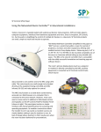
The AmpLINC Hub accepts all inputs and power and sends it
down Cat5 cable to the AmpLINC Pucks. All power and system
volume can be controlled on the Hub.
Two LED indicators on the left-hand side of the AmpLINC Hub will
illuminate when power is supplied (Power LED - blue) and when
signal is detected on either input (Sig LED - green). If the nodes
are not outputting any audio, first check to make sure that both
of these LEDs are illuminated.
Note - When the AmpLINC Hub goes into sleep mode due to no
signal, the LED will turn OFF. To turn the AmpLINC Hub back on,
make sure that signal is being sent to the Hub.
The system volume can be set using the recessed knob on the left
-hand side of the unit. To turn this, insert a small screwdriver into
the slot and turn clockwise to turn the volume up.
12
3.1.2 Output Connections
The AmpLINC Hub utilizes standard Cat5 cable to send both signal and power to the nodes connected to its ports. Regular Cat5
patch cables may be used, purchased in standard lengths or cut
and crimped for the installation. If making your own cables, standard A or B patch cable wiring can be used or straight through
connections between pin 1-8 to pin 1-8 on either end. Crossover
cables or wiring cannot be used.
Each port is capable of outputting a maximum of 20 total watts
of power to the nodes daisy chained on that port.
CAUTION: Do not connect the Hub or Pucks to any other
devices (such as a network router or switch). They are not
Ethernet capable and will damage other devices.
The total power output of the AmpLINC Hub is limited by the
power rating of the power supply which was purchased with the
system, and cannot exceed 80 Watts.
Each AmpLINC Hub port is capable of outputting a maximum of
20 watts of speaker power. This 20 watts is available for the AmpLINC Puck and speakers daisy chained to the port.
If you would like to upgrade the chosen power supply, please
contact your local sales rep for details.
3.2 Node Installation
Each AmpLINC Puck contains a single channel micro amplifier
capable of delivering up to 10 watts of power to a single
speaker.
If you have the SP-IC4 or SP-IC5 speakers as a part of your AmpLINC System, the Puck can be secured to the top of the
speaker. To secure the amplifier node, place the node on top of
the speaker inserting the screws on the top of the speaker into
the notches on the rear of the amplifier. Twist the node clockwise
and it will lock into place.
9